Electrical 87 Electrical Mess

@Southport2014

You jumpered the flasher socket contacts together, turned the ignition switch to Run and then turned the turn signal to either left or right and got nothing? No steady turn signal lights or either side?
 
  • Sponsors (?)


I jumpered the turn signal flasher. Got nothing.

Turn the ignition switch to Run; the engine does not need to be running for these tests. With the turn signal flasher removed, test the pink/orange wire for 12 volts. Remember that the turn signal flasher is not the one on the front of the fuse panel; it is located somewhere else.
Set the voltmeter to DC volts and select the scale that is closest to 12 volts. Clip one voltmeter probe on the bare metal part of the car body for a ground and put the other probe in the turn signal flasher socket contact that has the pink/orange wire. You should see about 12 volts.

No 12 volts present: replace the fuse and check for 12 volts again as described above. Do not turn the ignition switch off if you are testing for voltage.

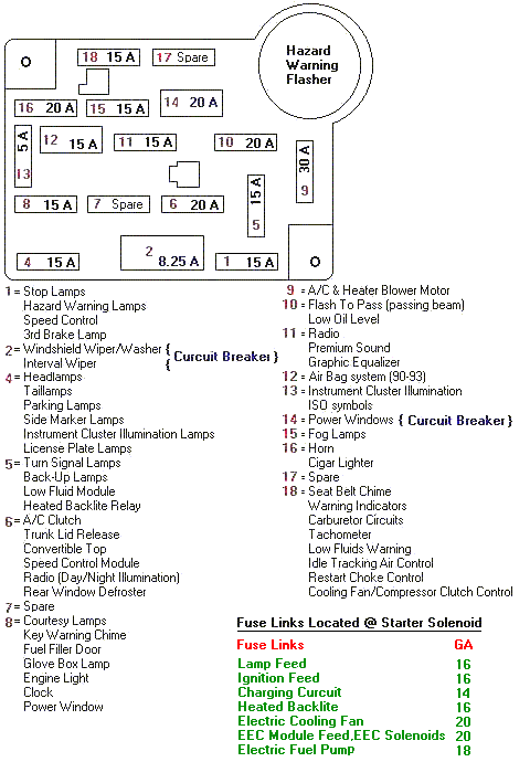
Still no 12 volts, pull the fuse and test the #5 fuse socket contacts for 12 volts. One contact will have 12 volts. One probe is grounded, the other probe gets stuck in the fuse contacts. Test both contacts for 12 volts.

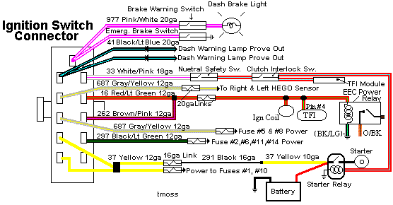
No 12 volts on either fuse contact, the ignition switch or ignition switch wiring is suspect. Move things around so that you can get to the backside of the ignition switch wiring connector with the ignition switch still connected to it. Make sure that you don't turn the ignition switch OFF while you are testing it. It still needs to be in the Run position. Look for 12 volts on the large gray/yellow wire. No 12 volts and you have a bad ignition switch or some bad wiring. Wiggle the large gray/yellow wire to see if it gets or loses voltage while you are checking it.

Diagrams courtesy of Tmoss & Stang&2birds

Fuse box layout
MustangFuseBox.gif


Ignition switch wiring
IgnitionSwitchWiring.gif


See the following website for some help from Tmoss (diagram designer) & Stang&2Birds (website host) for help on 88-95 wiring; Mustang FAQ - Wiring & Engine Info Everyone should bookmark this site.

94-95 Mustang wiring diagrams
Mustang FAQ - Wiring & Engine Info

Complete computer, actuator & sensor wiring diagram for 91-93 Mass Air Mustangs
http://www.veryuseful.com/mustang/tech/engine/images/91-93_5.0_EEC_Wiring_Diagram.gif

Complete computer, actuator & sensor wiring diagram for 88-91 Mass Air Mustangs
http://www.veryuseful.com/mustang/tech/engine/images/88-91_5.0_EEC_Wiring_Diagram.gif

Ignition switch wiring
http://www.veryuseful.com/mustang/tech/engine/images/IgnitionSwitchWiring.gif

Fuel, alternator, A/C and ignition wiring
http://www.veryuseful.com/mustang/tech/engine/images/fuel-alt-links-ign-ac.gif

O2 sensor wiring harness
http://www.veryuseful.com/mustang/tech/engine/images/mustangO2Harness.gif

Vacuum diagram 89-93 Mustangs
http://www.veryuseful.com/mustang/tech/engine/images/mustangFoxFordVacuumDiagram.jpg

HVAC vacuum diagram
http://www.veryuseful.com/mustang/tech/engine/images/Mustang_AC_heat_vacuum_controls.gif

TFI module differences & pin out
http://www.veryuseful.com/mustang/tech/engine/images/TFI_5.0_comparison.gif

Fuse box layout
http://www.veryuseful.com/mustang/tech/engine/images/MustangFuseBox.gif

Mustang 5.0 Lights and Radio schematic, by TMoss:
http://www.veryuseful.com/mustang/tech/engine/images/mustangFoxLights-Radio_diag.gif

87-92 power window wiring
http://www.veryuseful.com/mustang/tech/engine/images/mustang87-92 PowerWindowWiring.gif

93 power window wiring
http://www.veryuseful.com/mustang/tech/engine/images/mustang93PowerWindows.gif

T5 Cutaway showing T5 internal parts
http://www.veryuseful.com/mustang/tech/engine/images/5_Speed_Cutaway_Illustrated.jpg

Visual comparison of the Ford Fuel Injectors, picture by TMoss:
http://www.veryuseful.com/mustang/tech/engine/images/Ford_Injector_Guide.jpg

Convertible top motor wiring http://www.veryuseful.com/mustang/tech/engine/images/mustang88VertTopMotorCkt.gif

Engine mounted fuel injector harness
http://www.veryuseful.com/mustang/tech/engine/images/mustangEngineHarness.gif tang/tech/engine/images/mustang88VertTopMotorCkt.gif
 
Last edited:
Ok i got power to the relay. Still no turn signals. I have replaced the relay. I have replaced the fuse. I replaced the ignition switch. I borrowed a brand new turn signal assembly from the store and still did not dix the problem? Do you have any idea what it could be then ? I have a few things not hooked up plug wise i will send pics and maybe something needs plugged in idk . I have 20 hours om trying to figure this out its ridiculous. Picture 3 is the colt meter setting is thay the correct one ? If so the voltage was jumping from 1-6 picture 2 the green plug the other connector is broke does it need to be plugges in ? Picture 4 is a plug under the driver side fender well and i can not find where it plugs too. Pixture6 5 is another plug that is on the driver side and i do not know where it plugs too? Picture 6 has to black and yellow plugs i cant find where they hook into either
 

Attachments

  • 20151122_123254.jpg
    20151122_123254.jpg
    129.7 KB · Views: 107
  • 20151122_124202.jpg
    20151122_124202.jpg
    112.6 KB · Views: 138
  • 20151122_124131_001.jpg
    20151122_124131_001.jpg
    91.6 KB · Views: 109
  • 20151122_124403.jpg
    20151122_124403.jpg
    70.9 KB · Views: 125
  • 20151122_125042.jpg
    20151122_125042.jpg
    91.2 KB · Views: 118
  • 20151122_125053_001.jpg
    20151122_125053_001.jpg
    71.5 KB · Views: 97
@Southport2014,
I never said to replace anything. What I advised you to do was to step through the test path I laid out for you. Once you have worked your way through it, you will know why your flashers don't work.

The pictures you posted don't provide much useful information.
Tell me step by step what you observed going through the test path.
 
@Southport2014
Click on the drawing to enlarge

turn-signal-wiring-87-90-mustang-jpg.545554


All tests done with the ignition switch in the Run position

12 volts at pink/orange wire; yes or no?

12 volts at lt blue wire; yes or no? Try this with the turn signal set for either right turn or left turn and then for no turn..

12 volts at orange/yellow wire; yes or no?

12 volts at the lt green/white wire. Try this with the turn signal set for left turn. Good 12 volts? yes or no.

12 volts at the white/blue wire. Try this with the turn signal set for right turn. Good 12 volts? yes or no.
 

Attachments

  • Turn signal wiring 87-90 Mustang.jpg
    Turn signal wiring 87-90 Mustang.jpg
    34.4 KB · Views: 52,200
Last edited:
Pink orange- 11.2 volts
Blue wire -no volts at any position left right none
Orange yellow wire - no volts
Green white- no volts
White blue- no volts
@jrichker
That means the flasher isn't passing power. It is time for a new one.


The diagram set I sent you has a wire color chart (STANDARD CIRCUIT CHART (BY COLOR) on starting on page 9. Use the wire color chart to help you identify circuit names and components You will have to use some intelligence and realize that there are some things not found on a Mustang, like “DIESEL TACH GROUND TO TACH GAUGE MODULE”. That will help eliminate chasing rabbits that go nowhere.

Use the chart to find the wire color and then the circuit name. Use the COMPONENT INDEX on page 18 just before the actual wiring diagrams to find the circuit components location. It has the name of the electrical components in the Mustang; if you picked the DIESEL TACH ground and then didn’t find it in the COMPONENT INDEX, that is a pretty good clue that it isn’t found on a Mustang; go back and look for something else.

The diagrams are laid out in a grid system, numbers along the top and bottom (columns) and letters along the side (rows). The numbers increment by 11 every time there is a new page. The letters A-F are the same on every page. Pages go like this: page 1 starts with 1, page 2 starts with 12, page 3 starts with 23, page 4 starts with 34 and so on until you get to the end; the last page starts with 111. The higher the column number, the further back you are from the front of the car. This helps you get an idea of the physical location of a component. If it says that the location is F-111, that’s not going to be at the front of the car.

Look at location on the COMPONENT INDEX and you'll find turn signal flasher A-27, which turns out to be the 3rd diagram, top of the page, just left of the middle of the page, and on the first row (row A). Each component has the wire colors and circuit number associated with it printed in the wire path. You will notice that the circuit numbers change when power or signal goes in one connection on a component and comes out another connection on the same component. The component socket shape on the diagrams matches the actual socket shape that connects to the component.

Take a connector with wires attached and you can find out what it does. Use the wire color chart to find what the circuit is and then use the index to find the component location. Then make sure the wire colors on the diagram and connector shape match the diagram and you will have successfully identified what the connector plugs into and what it does.
 
Do you mean the tun signal relay ? Or what. Im getting power up to the flasher but none from it to the 4 way flasher module. And where is this standered color chart ? Also did you get thr pictures of the plugs i found they are same color as thr turn signal wires but idk where they hook up at.