I would advise you to clear the codes and see if the code 96 goes away and doesn't come back. It is one of those codes that can get set if the inertia switch trips or you disconnected something in the fuel pump circuit while troubleshooting.
Google is your friend...

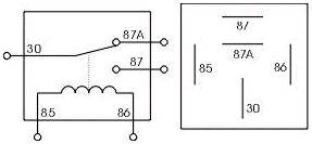
See
http://www.the12volt.com/relays/relays.asp for more help...
A refresher on the code 96 is below...
Code 96 for 86-90 model 5.0 Mustang – KOEO- Fuel pump monitor circuit shows no power - Fuel pump relay or battery power feed was open - Power / Fuel Pump Circuits. The fuel pump lost power at some time while the ignition switch was in the run position. The main power feed to the pump is what is losing power.
Look for a failing fuel pump relay, bad connections or broken wiring. Check the fuel pump relay for damage and check the socket for corrosion, overheated wiring or loose connections. The fuel pump relay is located under the passenger seat.
On Mass Air Conversions, the signal lead that tells the computer that the fuel pump has power may not have been wired correctly.
See
http://www.stangnet.com/tech/maf/massairconversion.html
Look for power at the fuel pump - the fuel pump has a connector at the rear of the car with a pink/black wire and a black wire that goes to the fuel pump. The pink/black wire should be hot when the test connector is jumpered to the test position. . To trick the fuel pump into running, find the ECC test connector and jump the connector in the lower RH corner to ground.
86-90 Models:
Using the diagram, check the red/black wire from the fuel pump relay: you should see 12 volts or so. If not, check the inertia switch: on a hatch it is on the drivers side by the taillight. Look for a black rubber plug that pops out: if you don't find it, then loosen up the plastic trim. Check for voltage on both sides of the switch. If there is voltage on both sides, then check the Pink/black wire on the fuel pump relay: it is the power feed to the fuel pump. Good voltage there, then the fuel pump body to tank wiring harness connector is the likely culprit since it is getting power. No voltage there, check the Orange/Lt blue wire, it is the power feed to the fuel pump relay & has a fuse link in it. Good voltage there & at the Pink/black wire, swap the relay.
Keep in mind that the relay wiring and socket can also cause intermittent problems. Clean the relay socket with non-flammable brake parts cleaner or electrical contact cleaner. If you find damaged wiring at the relay socket, replacement pigtail socket assemblies are available at the auto parts stores. Be sure to solder the wires and cover the solder joints with heat shrink tubing if you replace the relay socket.