Sn95 5.0 Engine Rebuild

  • Sponsors (?)


I think we all tried.... most of the big brains gave it a go, good advice, great advice...... ignored........ completely.

Yeah, I kinda saw that. Too bad. It's probably something simple too.. I went around and around with my son's car a while back.. Same symptoms. The fix was so simple..Interesting the things you learn fixing your own stuff. Frustrating as hell when you try to share it with someone and they totally ignore you.
 
I started to read this build in hopes it was another old fashioned rebuild. Page by page I was let down by the OP decisions. Good suggestions by veteran guys just ignored. I know we are here to help people ,even those that are very green, but why they ask for help and don't listen to valued options is beyond me. I mean no offense but this is almost comical.

So the only option you have is to sell your vert that is barely running. I doubt you'd get 5k for it in the condition you described. But, maybe it's for the best you don't have a mustang.

And as far as the new mustangs, while I prefer a 13-14, it is clear the new mustangs performance is pure awesomeness. Not sure what exactly you drove and why you hated it, but a brand new mustang would run circles around yours without even breathing heavily. They handle better and are way more comfortable.

Good luck with your sell sir. Hope it finds a good home.
 
  • Like
Reactions: 1 users
i give up im done .. thank you for all your help

no codes at all .....


Plan A:
I'll make you a deal that you can't pass up. Have the car transported to my driveway in Dublin GA. You pay for the transportation costs and I'll give you $10 for the car. Then I fix it so that it runs good and turn around and offer to sell it back to you for $4990...


If that doesn't seem like a bargain, here's plan B...

NO 11 code when you dumped the codes? Did you use the procedure at the top of the 5.0 Tech forum where the sticky threads are posted? One of them is how to dump the computer codes. Codes may be present even if the CEL (Check Engine Light) isn’t on. You don’t need a code reader or scanner – all you need is a paper clip, or if your lady friend has a hair pin, that will do the job.
I highly suggest that you read it and follow the instructions to dump the codes. http://www.stangnet.com/mustang-forums/threads/how-to-pull-codes-from-eec4.889006/

You succeeded in trying to dump the codes but still didn't get any codes at all - see below....

Computer will not go into diagnostic mode on 91-95 model 5.0 Mustangs

Revised 7-June-2014 to change resistance figures to wiring checks

How it is supposed to work:
The grey/red wire (pin 46) is signal ground for the computer. It provides a dedicated ground for the EGR, Baro, ACT, ECT, & TPS sensors as well as the ground to put the computer into self-test mode. If this ground is bad, none of the sensors mentioned will work properly. That will severely affect the car's performance. You will have hard starting, low power and drivability problems. Since it is a dedicated ground, it passes through the computer on its way to the computer main power ground that terminates at the battery pigtail ground. It should read less than 1 ohm when measured from anyplace on the engine harness with the battery pigtail ground as the other reference point for the ohmmeter probe.

What sometimes happens is that the test connector grey/red wire gets jumpered to power which either burns up the wiring or burns the trace off the pc board inside the computer. That trace connects pins 46 to pins 40 & 60.

The STI (Self Test Input ) is jumpered to ground to put the computer into test mode. Jumpering it to power can produce unknown results, including damage to the computer. The ohm test simply verifies that there are no breaks in the wiring between the test connector and the computer input.

How to test the wiring :
With the power off, measure the resistance between the computer test ground (grey/red wire) on the self- test connector and battery ground. You should see less than 1 ohm.

attachment.php?attachmentid=40907&d=1134531771.jpg


If that check fails, remove the passenger side kick panel and disconnect the computer connector. There is a 10 MM bolt that holds it in place. Measure the resistance between the grey/red wire and pin 46 on the computer wiring connector: it should be less than 1 ohm. More than 1 ohm is a wiring problem. If it reads 1 ohm or less, then the computer is suspect. On the computer, measure the resistance between pin 46 and pins 40 & 60: it should be less than 1 ohm. More than that and the computer’s internal ground has failed, and the computer needs to be repaired or replaced.

See http://www.stangnet.com/mustang-forums/749974-computer-issue.html#post7490537 for Joel5.0’s fix for the computer internal signal ground.

If the first ground check was good, there are other wires to check. Measure the resistance between the STI computer self-test connector (red/white wire) and pin 48 on the computer main connector: it should be less than 1.5 ohms. More than 1 ohms is a wiring problem

The following is a view from the computer side of the computer wiring connector: it is for an A9L, A9P computer.
eec-iv-computer-connector-for-5-0-mustang-gif.88243.gif


a9x-series-computer-connector-wire-side-view-gif.71316.gif


Diagram courtesy of Tmoss & Stang&2birds

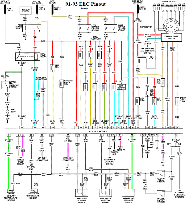
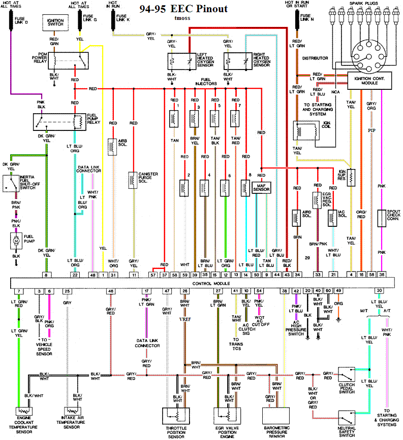
Check out the diagram and notice all the places the grey/red wire goes. Almost every sensor on the engine except the MAF is connected to it.

91-93 5.0 Mustangs
91-93_5.0_EEC_Wiring_Diagram.gif


Complete computer, actuator & sensor wiring diagram for 94-95 Mass Air Mustangs
94-95_5.0_EEC_Wiring_Diagram.gif


See the graphic for the 10 pin connector circuit layout.
salt-pepper-10-pin-connectors-65-jpg.68512


See the following website for some help from Tmoss (diagram designer) & Stang&2Birds
(website host) for help on 88-95 wiring http://www.veryuseful.com/mustang/tech/engine
 
Last edited:
  • Like
Reactions: 2 users
so i did codes ... i had to take my shoes off for a few ... now i AM uploading 2 vids with all 3 tests and im pretty sure i counted correctly

Key on engine off
3
564
1
172
176
Key on engine on
4
3
116
536
632
and 3rd test was you give it some gas and it reads each bank or something like that
9

again il post vids when done uploading ... (hours) have slow internet
 
Plan A:
I'll make you a deal that you can't pass up. Have the car transported to my driveway in Dublin GA. You pay for the transportation costs and I'll give you $10 for the car. Then I fix it so that it runs good and turn around and offer to sell it back to you for $4990...


If that doesn't seem like a bargain, here's plan B...

NO 11 code when you dumped the codes? Did you use the procedure at the top of the 5.0 Tech forum where the sticky threads are posted? One of them is how to dump the computer codes. Codes may be present even if the CEL (Check Engine Light) isn’t on. You don’t need a code reader or scanner – all you need is a paper clip, or if your lady friend has a hair pin, that will do the job.
I highly suggest that you read it and follow the instructions to dump the codes. http://www.stangnet.com/mustang-forums/threads/how-to-pull-codes-from-eec4.889006/

You succeeded in trying to dump the codes but still didn't get any codes at all - see below....

Computer will not go into diagnostic mode on 91-95 model 5.0 Mustangs

Revised 7-June-2014 to change resistance figures to wiring checks

How it is supposed to work:
The grey/red wire (pin 46) is signal ground for the computer. It provides a dedicated ground for the EGR, Baro, ACT, ECT, & TPS sensors as well as the ground to put the computer into self-test mode. If this ground is bad, none of the sensors mentioned will work properly. That will severely affect the car's performance. You will have hard starting, low power and drivability problems. Since it is a dedicated ground, it passes through the computer on its way to the computer main power ground that terminates at the battery pigtail ground. It should read less than 1 ohm when measured from anyplace on the engine harness with the battery pigtail ground as the other reference point for the ohmmeter probe.

What sometimes happens is that the test connector grey/red wire gets jumpered to power which either burns up the wiring or burns the trace off the pc board inside the computer. That trace connects pins 46 to pins 40 & 60.

The STI (Self Test Input ) is jumpered to ground to put the computer into test mode. Jumpering it to power can produce unknown results, including damage to the computer. The ohm test simply verifies that there are no breaks in the wiring between the test connector and the computer input.

How to test the wiring :
With the power off, measure the resistance between the computer test ground (grey/red wire) on the self- test connector and battery ground. You should see less than 1 ohm.

attachment.php?attachmentid=40907&d=1134531771.jpg


If that check fails, remove the passenger side kick panel and disconnect the computer connector. There is a 10 MM bolt that holds it in place. Measure the resistance between the grey/red wire and pin 46 on the computer wiring connector: it should be less than 1 ohm. More than 1 ohm is a wiring problem. If it reads 1 ohm or less, then the computer is suspect. On the computer, measure the resistance between pin 46 and pins 40 & 60: it should be less than 1 ohm. More than that and the computer’s internal ground has failed, and the computer needs to be repaired or replaced.

See http://www.stangnet.com/mustang-forums/749974-computer-issue.html#post7490537 for Joel5.0’s fix for the computer internal signal ground.

If the first ground check was good, there are other wires to check. Measure the resistance between the STI computer self-test connector (red/white wire) and pin 48 on the computer main connector: it should be less than 1.5 ohms. More than 1 ohms is a wiring problem

The following is a view from the computer side of the computer wiring connector: it is for an A9L, A9P computer.
eec-iv-computer-connector-for-5-0-mustang-gif.88243.gif


a9x-series-computer-connector-wire-side-view-gif.71316.gif


Diagram courtesy of Tmoss & Stang&2birds

Check out the diagram and notice all the places the grey/red wire goes. Almost every sensor on the engine except the MAF is connected to it.

91-93 5.0 Mustangs
91-93_5.0_EEC_Wiring_Diagram.gif


Complete computer, actuator & sensor wiring diagram for 94-95 Mass Air Mustangs
94-95_5.0_EEC_Wiring_Diagram.gif


See the graphic for the 10 pin connector circuit layout.
salt-pepper-10-pin-connectors-65-jpg.68512.jpg


See the following website for some help from Tmoss (diagram designer) & Stang&2Birds
(website host) for help on 88-95 wiring http://www.veryuseful.com/mustang/tech/engine


ya none of that made any sense to me
 
so i did codes ... i had to take my shoes off for a few ... now i AM uploading 2 vids with all 3 tests and im pretty sure i counted correctly

Key on engine off
3
564
1
172
176
Key on engine on
4
3
116
536
632
and 3rd test was you give it some gas and it reads each bank or something like that
9

again il post vids when done uploading ... (hours) have slow internet


OBD I codes are two numbers
OBDII are three numbers

If you got 9 on the cylinder balance test then uh..... your NINTH cylinder is bad.
 
so going over i have the fallowing
key on engine off
flicker
564 ElectrOD FAN( EDF) circuit failure
1 what is this????
172 Lack of Oxygen Sensor (HEGO) Switches, indicates lean (how not in key on engine off test)
176 what is this?????

that is from first vid i think
 
so going over i have the fallowing
key on engine off
flicker
564 ElectrOD FAN( EDF) circuit failure
1 what is this????
172 Lack of Oxygen Sensor (HEGO) Switches, indicates lean (how not in key on engine off test)
176 what is this?????

that is from first vid i think

Code 564 Fan Control (FC) circuit failure – A/C and Fan Circuits - look for CCM problems - bad fan control relay or bad fan wiring.

Code 41 or 91. Or 43 Three digit code 172 or 176 - O2 sensor indicates system lean. Look for a vacuum leak or failing O2 sensor.

Revised 11-Jan-2015 to add check for fuel pressure out of range

Code 41 is the passenger side sensor, as viewed from the driver's seat.
Code 91 is the driver side sensor, as viewed from the driver's seat.

Code 172 is the passenger side sensor as viewed from the driver's seat.
Code 176 is the driver side sensor, as viewed from the driver's seat.

Code 43 is not side specific according to the Probst Ford Fuel injection book.

The computer sees a lean mixture signal coming from the O2 sensors and tries to compensate by adding more fuel. Many times the end result is an engine that runs pig rich and stinks of unburned fuel.

The following is a Quote from Charles O. Probst, Ford fuel Injection & Electronic Engine control:
"When the mixture is lean, the exhaust gas has oxygen, about the same amount as the ambient air. So the sensor will generate less than 400 Millivolts. Remember lean = less voltage.

When the mixture is rich, there's less oxygen in the exhaust than in the ambient air , so voltage is generated between the two sides of the tip. The voltage is greater than 600 millivolts. Remember rich = more voltage.

Here's a tip: the newer the sensor, the more the voltage changes, swinging from as low as 0.1 volt to as much as 0.9 volt. As an oxygen sensor ages, the voltage changes get smaller and slower - the voltage change lags behind the change in exhaust gas oxygen.

Because the oxygen sensor generates its own voltage, never apply voltage and never measure resistance of the sensor circuit. To measure voltage signals, use an analog voltmeter with a high input impedance, at least 10 megohms. Remember, a digital voltmeter will average a changing voltage." End Quote

Testing the O2 sensors 87-93 5.0 Mustangs
Measuring the O2 sensor voltage at the computer will give you a good idea of how well they are working. You'll have to pull the passenger side kick panel off to gain access to the computer connector. Remove the plastic wiring cover to get to the back side of the wiring. Use a safety pin or paper clip to probe the connections from the rear.

Disconnect the O2 sensor from the harness and use the body side O2 sensor harness as the starting point for testing. Do not measure the resistance of the O2 sensor , you may damage it. Resistance measurements for the O2 sensor harness are made with one meter lead on the O2 sensor harness and the other meter lead on the computer wire or pin for the O2 sensor.

Backside view of the computer wiring connector:
a9x-series-computer-connector-wire-side-view-gif.71316.gif


87-90 5.0 Mustangs:
Computer pin 43 Dark blue/Lt green – LH O2 sensor
Computer pin 29 Dark Green/Pink – RH O2 sensor
The computer pins are 29 (L\RH O2 with a dark green/pink wire) and 43 (LH O2 with a dark blue/pink wire). Use the ground next to the computer to ground the voltmeter. The O2 sensor voltage should switch between .2-.9 volt at idle.

91-93 5.0 Mustangs:
Computer pin 43 Red/Black – LH O2 sensor
Computer pin 29 Gray/Lt blue – RH O2 sensor
The computer pins are 29 (LH O2 with a Gray/Lt blue wire) and 43 (RH O2 with a Red/Black wire). Use the ground next to the computer to ground the voltmeter. The O2 sensor voltage should switch between .2-.9 volt at idle.


Testing the O2 sensors 94-95 5.0 Mustangs
Measuring the O2 sensor voltage at the computer will give you a good idea of how well they are working. You'll have to pull the passenger side kick panel off to gain access to the computer connector. Remove the plastic wiring cover to get to the back side of the wiring. Use a safety pin or paper clip to probe the connections from the rear. The computer pins are 29 (LH O2 with a red/black wire) and 27 (RH O2 with a gray/lt blue wire). Use pin 32 (gray/red wire) to ground the voltmeter. The O2 sensor voltage should switch between .2-.9 volt at idle.


Note that all resistance tests must be done with power off. Measuring resistance with a circuit powered on will give false readings and possibly damage the meter. Do not attempt to measure the resistance of the O2 sensors, it may damage them.

Testing the O2 sensor wiring harness
Most of the common multimeters have a resistance scale. Be sure the O2 sensors are disconnected and measure the resistance from the O2 sensor body harness to the pins on the computer. Using the Low Ohms range (usually 200 Ohms) you should see less than 1.5 Ohms.

87-90 5.0 Mustangs:
Computer pin 43 Dark blue/Lt green – LH O2 sensor
Computer pin 29 Dark Green/Pink – RH O2 sensor
Disconnect the connector from the O2 sensor and measure the resistance:
From the Dark blue/Lt green wire in the LH O2 sensor harness and the Dark blue/Lt green wire on the computer pin 43
From the Dark Green/Pink wire on the RH Os sensor harness and the Dark Green/Pink wire on the computer pin 29

91-93 5.0 Mustangs:
Computer pin 43 Red/Black – LH O2 sensor
Computer pin 29 Gray/Lt blue – RH O2 sensor
Disconnect the connector from the O2 sensor and measure the resistance:
From the Red/Black wire in the LH O2 sensor harness and the Red/Black wire on the computer pin 43
From the Dark Green/Pink Gray/Lt blue wire on the RH Os sensor harness and the Gray/Lt blue wire on the computer pin 29

94-95 5.0 Mustangs:
Computer pin 29 Red/Black – LH O2 sensor
Computer pin 27 Gray/Lt blue – RH O2 sensor
From the Red/Black wire in the LH O2 sensor harness and the Red/Black wire on the computer pin 29
From the Dark Green/Pink Gray/Lt blue wire on the RH Os sensor harness and the Gray/Lt blue wire on the computer pin 27

There is a connector between the body harness and the O2 sensor harness. Make sure the connectors are mated together, the contacts and wiring are not damaged and the contacts are clean and not coated with oil.

The O2 sensor ground (orange wire with a ring terminal on it) is in the wiring harness for the fuel injection wiring. I grounded mine to one of the intake manifold bolts

Check the fuel pressure – the fuel pressure is 37-41 PSI with the vacuum disconnected and the engine idling. Fuel pressure out of range can cause the 41 & 91 codes together. It will not cause a single code, only both codes together.

Make sure you have the proper 3 wire O2 sensors. Only the 4 cylinder cars used a 4 wire sensor, which is not compatible with the V8 wiring harness.

Replace the O2 sensors in pairs if replacement is indicated. If one is weak or bad, the other one probably isn't far behind.

Code 41 can also be due to carbon plugging the driver’s side Thermactor air crossover tube on the back of the engine. The tube fills up with carbon and does not pass air to the driver’s side head ports. This puts an excess amount of air in the passenger side exhaust and can set the code 41. Remove the tube and clean it out so that both sides get good airflow: this may be more difficult than it sounds. You need something like a mini rotor-rooter to do the job because of the curves in the tube. Something like the outer spiral jacket of a flexible push-pull cable may be the thing that does the trick.

If you get only code 41 and have changed the sensor, look for vacuum leaks. This is especially true if you are having idle problems. The small plastic tubing is very brittle after many years of the heating it receives. Replace the tubing and check the PVC and the hoses connected to it.


.. ok where is and what does the O2 sensor look like ?