
This is the BIG one that everyone seems to like...so i thought I would write down some of the info I've learned in my swap so Its available to everyone here...
General Swap Info
So there's a few things that you'll need to know....
1) the Year of the AOD that your looking at purchasing
2) the size of your C4
3)What your AOD was out of
---------------------------------------------------------
1)
The reason why I say you want to know the YEAR of the AOD your looking at is for one big reason. The AOD got electronic controls in 1991, becoming the AODE. Although the AODE should work, the reason why you don't want to use them is b/c they are electronically controlled. If you used the AODE, you would need the wiring harness, the ECU and all those goodies to go along with it. So for simplicities sake, we'll stick with a pre-'91 AOD
2)
There are two types of C-4 : (small bell housing) and (large bell housing). The small bell housing C-4 will have a 157 tooth flexplate. THIS IS TOO SMALL! the AOD will require a 164 tooth flexplate. This can be found in any 1969 and up 351 (windsor or cleveland) motor.
However, the large bell housing C-4 will have the larger 164 tooth flexplate and you should be able to use it with the AOD.
the way to tell these two apart is that the (small) c-4's dipstick enters into the pan, while the (large) c-4's dipstick enters into the bell housing itself.
from what I understand, the block plate from the (large) C-4 will also work with the AOD, otherwise, just get one for an AOD.
ALSO NOTE::: the flexplate MUST be a 28 oz imbalance. The newer flexplates have a 50 oz. imbalance and this will NOT work in your classic motor.
3)
the reason why i say "what the AOD" was out of is for just one reason. The AOD that was in the column shift vehicle will have the shift lever pointing up, and the floor shift units will have it pointing down. Now no need to worry, the column shift modules can be switched to work with the mustang application, I'll go over that a bit later, but its just one nice little piece of information to know right now.
Modifying the AOD
now comes the fun stuff..
there's a few things that I did to my C-4, and ALOT more that you can do. The website to go to for this is "clickclickracing.com" if you go to their general tech section, you'll find lots of info on all the automatics, but this is the section i'm mainly concerned with:
AOD/E/4R70W High Performance Modifications - Click Click Racing Forums
this is the thread for "performance modifications" and I did a few modifications which I'll outline here
1) shift kits
2) valve body modifications
3) input shaft modifications
1)
I put a shift into my AOD. I went with the B&M kit. Now most will tell you that the transgo kit is THE best out there. I have no idea, but what i have heard is that although the B&M kit will give you an upgrade from stock, It's not near a good as the transgo kit. I can't vouch for this at all, just passing along information.
the kit was very easy to install, directions were clear and it can be done in 2-3 hours pretty easily.
2)
There's some companies (like LenTech) out there that make a new valve body for the AOD that can give you full manual control.
The main reason for this is the notorious "1-d-1" shuffle. the shift pattern of the AOD is 1- 2/3 - 4 . For those of us that want to hold onto 2nd gear, this can be a bit frustrating. The way "most" do this, is by shifting it into (2/3) and then back into 1, holding 2nd gear. This can wreak h3ll on your AOD and lead to premature wear and breakage. There is however one way to change this called the "Epoxy mod"
first a few things on the mod:
Posatives
-Lets you hold 2nd gear
-effectively changes the shifting pattern to 1 - 2 - 3/4
-very easy and quick to do
Negatives
-requires drilling the v/b, not that big of an issue, but just something to be aware of
-since 3/4 are now on the same valve, what can happen is your car will shift into O/d in street driving, being problematic at times.
***the above however can be improved.
now for the mod:
(courtesy of dan at click click)
3)
The input shaft (at times) can become completely seated against the back and as a result, proper lubrication is not supplied to the sun gear and its components, by doing the following: you can eliminate this problem:
(once again, courtesy of dan)
Now there are many more modifications that can be done, (clutch packs, etc..) but these are just the ones that I did to my AOD
The Actual Swap
Here is a (rough general) outline of what you'll need to do to physically take out and put back in the C-4 and AOD.
(I'll get some pics of this this afternoon)
1) disconnect your exhaust
2) Take off the driveshaft
3) disconnect all the leads/lines to the C-4
4) unbolt the tranny from its x-member
5) remove the starter
6) unbolt the torque converter
7) support the engine
8) remove the tranny
1)
this will enable you to swing (or completely disconnect) your exhaust out of the way to make it easier getting the transmission in/out.
2)
The easiest way I've found to do this is to remove the clamp's from the rear of the driveshaft (where it meets the rear diff) and then slide the yoke out of the transmission.
***BE SURE! to have a catch pan underneath the tranny b/c fluid WILL come out!
3)
there are lots of lines/wires and linkages that are connected to the C-4. Here are (all of that i can remember) that will need to be taken off:
1-shift linkage
2-tranny cooling lines
3- reverse lockout switch wires
4-vacuum line
4)
there are just two bolts that stick out below the cross member to hold the tranny down, simply take the nuts off of this for now.
5)
I always have one helluva time trying to get my starter in/out. It may be easier to put a long (VERY LONG) extension and try and operate the ratchet from up by the battery tray/radiator area.
6)
In order to do this, you first must take off the dust cover from the tranny. If you rotate the flexplate, you should see four bolts where the torque converter attaches to the flexplate. take the nuts off of these and the covnerter should be free from the flexplate
7)
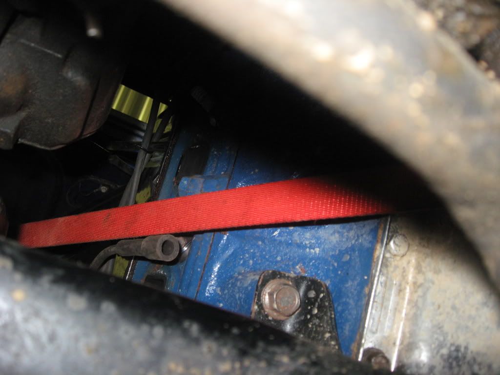
Obviously the engine doesn't have any support in the rear anymore. So just for safety reasons, I put a ratchet strap underneath the rear of the motor and attached it to the shock towers in order to keep the motor in balance.
8)
The first thin you need to do (and this will be much easier with a floor jack) is support the tranny. By putting a 2x6 under the tranny, the floor jack will be able to balance the tranny quite nicely. Now after that's done, the next step is to remove the x-member. This is just the removal of two bolts up on the frame. After the x-member is out, the next step is to start taking the bolts for the transmission out. There are (seven) in total.
Once all of the bolts are out, the fun begins. You'll most likely have to pry the transmission away from the motor with a screwdriver to help it along.....It'll take some finagling around, but once the studs on the torque converter are free of the flexplate, you can drop the jack slowly and WOOO!!! the transmissions out.
Now for putting the AOD back in. First however, there are a few things that you'll need to do:
remember earlier when i said that there was a difference between the column/floor shift AOD's ?? That can easily be changed. Before you button the pan of that AOD back up, take a look at the shift linkage. There should be a large nut on the (inside the tranny) shift rod. If you back this nut as far off as you can, you can pop off the shift linkage inside the tranny and freely rotate the shift lever on the outside of the tranny. Don't worry, the shaft is notched, just rotate the lever 180* and bingo! you've got a brand new floor shift AOD!")
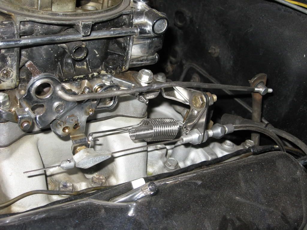
next, Lokar makes a kit (available through summit) for the Throttle valve linkage. This is how the AOD makes the decision when to shift. Unlike the C-4, it operates off of the position of your throttle, v/s a vacuum. Install this kit per the instructions and your ready to go.
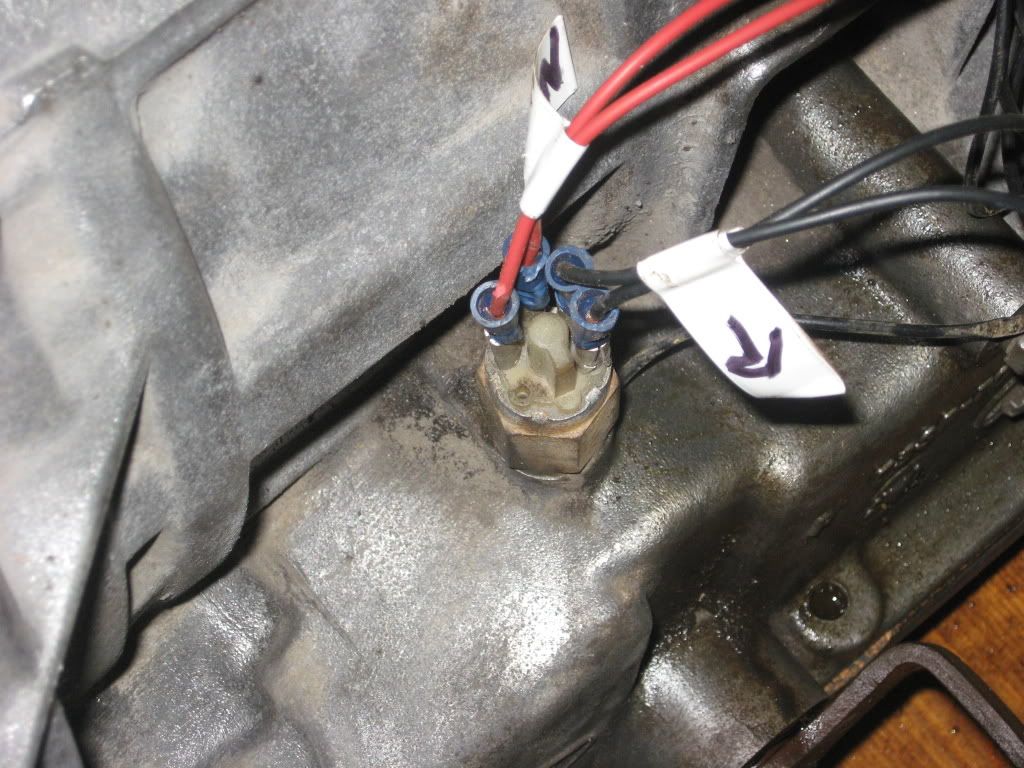
next, the AOD (unlike the C-4) has a built in reverse lockout switch. This means that either you'll have to make your own plug, or save the one with the tranny and splice into it. There's four pegs (two sets of two) separated by a **triangular** looking piece of plastic. With the "point" up, the two on the left are your Park/Neutral safety switch, and the two to the right are for the reverse lights.
but before you get all uppidy and start putting that new transmission in, lets doa few things first....
theres a couple of things that you won't need anymore and can be removed.
1-The kickdown cable from the accelerator
2- the vacuum line comming from the manifold
Once you've got those things taken care of, now its time for the installation!
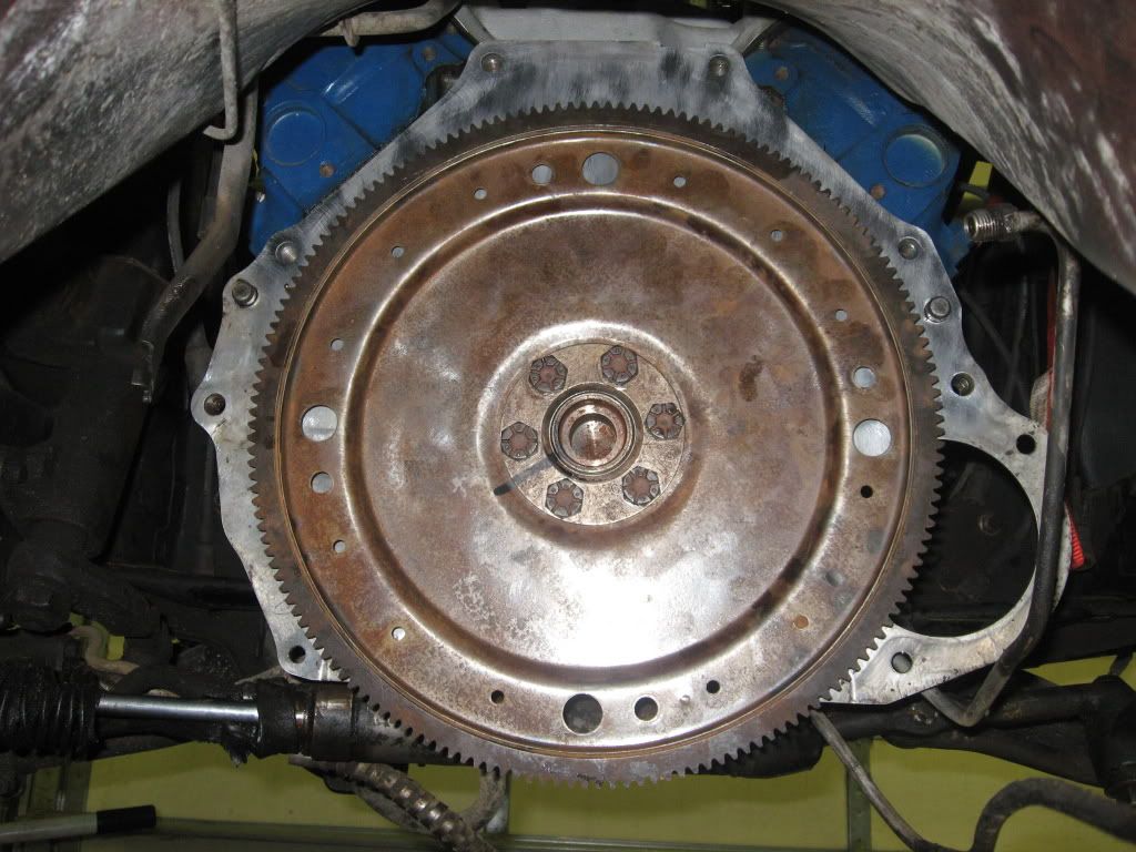
first, put your new flexplate on. DONT BE ALARMED if your holes don't line up perfectly. Instead of providing an "alignment hole" , ford simply offset their holes for the bolts. Simply rotate the flexplate until all six holes line up. Match the round "doughnut" to the holes, and you can bolt it in.
from here on out, its baisically the reverse order of taking the C-4 out. However, there are a few things that you'll need to know before your ready for the street:
Stuff you need to do/know
the AOD's mounting point is ~2" farther aft than the C-4, despite it only being 1/2" longer. This means that you'll need a new mounting bracket. Several companies make their own that you can buy, or like me, you can make your own.
as mentioned above, the AOD is ~1/2" longer than the C-4. This is just enough to make a difference in your drive shaft length. You'll need to get a new driveshaft or get your original one cut down or find one in a junkyard of the correct length. if you go with this last option, be sure the front fingers are for the same size bearing as the AOD's yoke, and make sure that it will accept the yoke from the rear differential.
The shift linkage length is just a tad different than the C-4. Summit makes a kit for this, or you can simply make/modify your own linkage like i did.
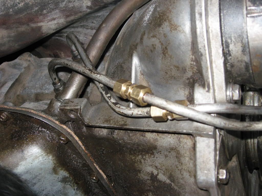
The trans cooler lines on the C-4 are in a completely different location than the AOD. They're both on the same SIDE, but in different spots. Either you'll need to modify the existing lines to re-route them, or buy new ones pre bent to fit or buy some line and bend your own.
AND NOW FOR THE MOST IMPORTANT PART!!!!!!!!!!
by now you should have everything put together and ready to go. BUT WAIT! before you tear around the street, be sure to properly set your throttle valve pressure!!!!! without doing so, you will burn up a perfectly good AOD. If you go with the lokar kit for the T/v linkage, it details in the instructions how to properly set your pressure. As a rule of thumb, it should be at 3 lbs at idle, and then as soon as you hit throttle, it should go up to 34 lbs.
how to set the proper pressure for both rod and cable style linkages:
(from the TCI auto website)
remember earlier when i said that in 3/4 the O/d likes to kick in a lower RPM's ?? This can be helped by either installing a new T/v proportioning valve, or by bumping up the pressure a little bit...although you don't want EXCESSIVELY high pressure, a higher than normal pressure will help with this issue a little bit.
more info on this can be found on the click click site i mentioned early in the post.
and that should be it!
if any of your guys who have done this before think i missed something, please let me know. I'm sorry for the lack of pictures, but I'll get some more this afternoon and as the project finishes up.
thanks to everyone for looking!
The Actual Swap
7)
Obviously the engine doesn't have any support in the rear anymore. So just for safety reasons, I put a ratchet strap underneath the rear of the motor and attached it to the shock towers in order to keep the motor in balance.
remember earlier when i said that there was a difference between the column/floor shift AOD's ?? That can easily be changed. Before you button the pan of that AOD back up, take a look at the shift linkage. There should be a large nut on the (inside the tranny) shift rod. If you back this nut as far off as you can, you can pop off the shift linkage inside the tranny and freely rotate the shift lever on the outside of the tranny. Don't worry, the shaft is notched, just rotate the lever 180* and bingo! you've got a brand new floor shift AOD!
however, the floor shift lever IS different than the column shift lever. In order to get proper linkage ratios so your stock shifter gate can work, you can clamp on a short piece of steel to the arm and run through the gear links. Once you find a angle/length that works, weld it in!
the way to tell between the two is that the column shift will be straight when viewing it from the side, where the floor shift will have a ~90* bend in it.
next, Lokar makes a kit (available through summit) for the Throttle valve linkage. This is how the AOD makes the decision when to shift. Unlike the C-4, it operates off of the position of your throttle, v/s a vacuum. Install this kit per the instructions and your ready to go.
summit p/n : LOK-KD2AODHT
next, the AOD (unlike the C-4) has a built in reverse lockout switch. This means that either you'll have to make your own plug, or save the one with the tranny and splice into it. There's four pegs (two sets of two) separated by a **triangular** looking piece of plastic. With the "point" down, the two on the left are your Park/Neutral safety switch, and the two to the right are for the reverse lights.
**note the "r" is the reverse light
first, put your new flexplate on. DONT BE ALARMED if your holes don't line up perfectly. Instead of providing an "alignment hole" , ford simply offset their holes for the bolts. Simply rotate the flexplate until all six holes line up. Match the round "doughnut" to the holes, and you can bolt it in.
Stuff you need to do/know
the AOD's mounting point is ~2" farther aft than the C-4, despite it only being 1/2" longer. This means that you'll need a new mounting bracket. Several companies make their own that you can buy, or like me, you can make your own.
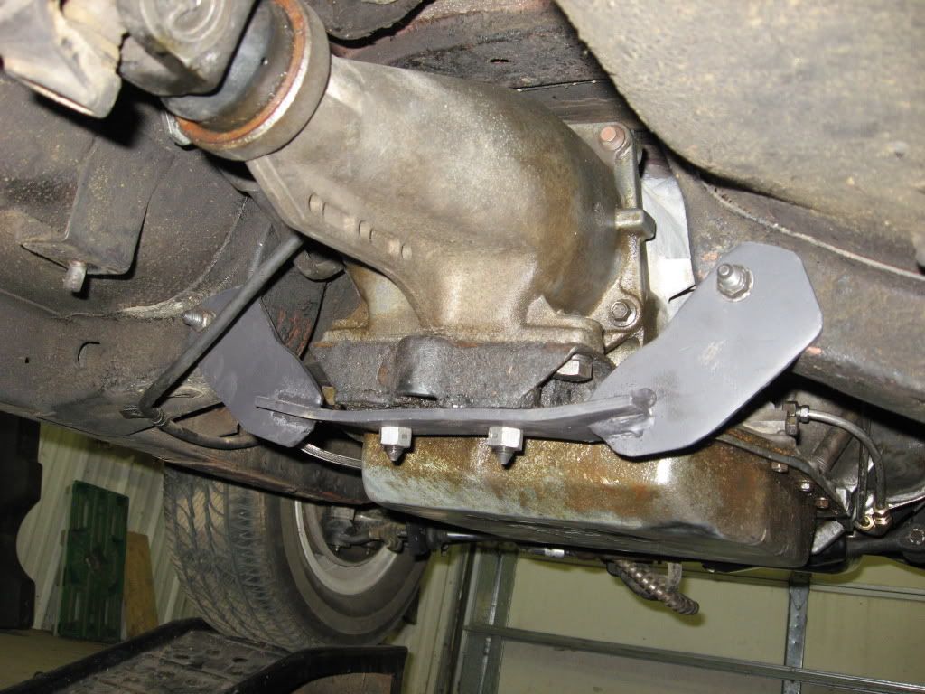
note: the tranny mount from the C4 will work.
as mentioned above, the AOD is ~1/2" longer than the C-4. This is just enough to make a difference in your drive shaft length. You'll need to get a new driveshaft or get your original one cut down or find one in a junkyard of the correct length. if you go with this last option, be sure the front fingers are for the same size bearing as the AOD's yoke, and make sure that it will accept the yoke from the rear differential.
*****I did NOT have to cut mine down, this probably will be different for everyones car. Also, if you cut down the C4 yoke to where the splines start, the C4 yoke will work with the AOD, so you can use the same knuckles on your original driveshaft.
The trans cooler lines on the C-4 are in a completely different location than the AOD. They're both on the same SIDE, but in different spots. Either you'll need to modify the existing lines to re-route them, or buy new ones pre bent to fit or buy some line and bend your own.
UPDATES
here are a few things i found usefull along the way:
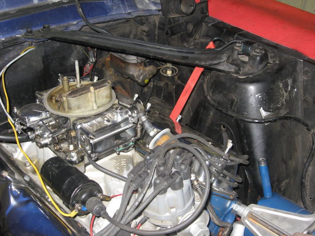
i suggest using the mounting bracket lokar has for their accelerator/kickdown cables. It makes life easy. Here's a picture of it installed on my carb:
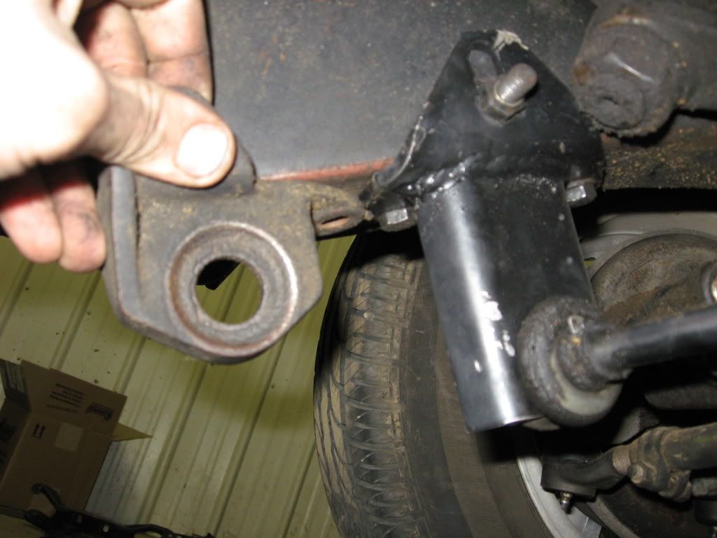
also, I had issues with the longtubes hitting on my P/S ram on the drivers side. You can purchase a drop bracket and it clears up this problem. here's the comparison between the stock and the drop:
however, the longtubes i have would also hit the bellhousing on the passengers side. I've ordered a pair of longtubes for a 86' Fox (per floor shift automatic applications) and I'll let you know how those fit in a classic when they come. If anything, you can run shroties. But supposedly headman makes long's SPECIFICALLY for AOD's. if you have headers for a C6 also, those will work, as the AOD is ~the same with as the C6.
General Swap Info
So there's a few things that you'll need to know....
1) the Year of the AOD that your looking at purchasing
2) the size of your C4
3)What your AOD was out of
---------------------------------------------------------
1)
The reason why I say you want to know the YEAR of the AOD your looking at is for one big reason. The AOD got electronic controls in 1991, becoming the AODE. Although the AODE should work, the reason why you don't want to use them is b/c they are electronically controlled. If you used the AODE, you would need the wiring harness, the ECU and all those goodies to go along with it. So for simplicities sake, we'll stick with a pre-'91 AOD
2)
There are two types of C-4 : (small bell housing) and (large bell housing). The small bell housing C-4 will have a 157 tooth flexplate. THIS IS TOO SMALL! the AOD will require a 164 tooth flexplate. This can be found in any 1969 and up 351 (windsor or cleveland) motor.
However, the large bell housing C-4 will have the larger 164 tooth flexplate and you should be able to use it with the AOD.
the way to tell these two apart is that the (small) c-4's dipstick enters into the pan, while the (large) c-4's dipstick enters into the bell housing itself.
from what I understand, the block plate from the (large) C-4 will also work with the AOD, otherwise, just get one for an AOD.
ALSO NOTE::: the flexplate MUST be a 28 oz imbalance. The newer flexplates have a 50 oz. imbalance and this will NOT work in your classic motor.
3)
the reason why i say "what the AOD" was out of is for just one reason. The AOD that was in the column shift vehicle will have the shift lever pointing up, and the floor shift units will have it pointing down. Now no need to worry, the column shift modules can be switched to work with the mustang application, I'll go over that a bit later, but its just one nice little piece of information to know right now.
Modifying the AOD
now comes the fun stuff..
there's a few things that I did to my C-4, and ALOT more that you can do. The website to go to for this is "clickclickracing.com" if you go to their general tech section, you'll find lots of info on all the automatics, but this is the section i'm mainly concerned with:
AOD/E/4R70W High Performance Modifications - Click Click Racing Forums
this is the thread for "performance modifications" and I did a few modifications which I'll outline here
1) shift kits
2) valve body modifications
3) input shaft modifications
1)
I put a shift into my AOD. I went with the B&M kit. Now most will tell you that the transgo kit is THE best out there. I have no idea, but what i have heard is that although the B&M kit will give you an upgrade from stock, It's not near a good as the transgo kit. I can't vouch for this at all, just passing along information.
the kit was very easy to install, directions were clear and it can be done in 2-3 hours pretty easily.
2)
There's some companies (like LenTech) out there that make a new valve body for the AOD that can give you full manual control.
The main reason for this is the notorious "1-d-1" shuffle. the shift pattern of the AOD is 1- 2/3 - 4 . For those of us that want to hold onto 2nd gear, this can be a bit frustrating. The way "most" do this, is by shifting it into (2/3) and then back into 1, holding 2nd gear. This can wreak h3ll on your AOD and lead to premature wear and breakage. There is however one way to change this called the "Epoxy mod"
first a few things on the mod:
Posatives
-Lets you hold 2nd gear
-effectively changes the shifting pattern to 1 - 2 - 3/4
-very easy and quick to do
Negatives
-requires drilling the v/b, not that big of an issue, but just something to be aware of
-since 3/4 are now on the same valve, what can happen is your car will shift into O/d in street driving, being problematic at times.
***the above however can be improved.
now for the mod:
(courtesy of dan at click click)
Drill: 3/32, 3 holes, inline with VB passage.


Clean, make sure manual valve is free to move. Grease valve like shown (vasoline / oil)

Block in place like so:

JB WELD is the epoxy used in this modification
Apply, and keep OUT of the holes you drilled - you can clean holes out like I had too before you leave it to dry

Set up and block, make sure cover is oiled so it can be removed.

Done

Veiw from outside looking in

3)
The input shaft (at times) can become completely seated against the back and as a result, proper lubrication is not supplied to the sun gear and its components, by doing the following: you can eliminate this problem:
(once again, courtesy of dan)
Just as mentioned above, the direct drum splines can wear, causing the direct drum shaft to contact the output shaft and shut off lube flow and ruin the sungear/planet support bushings. This is most commonly cause by converter ballooning.
Previous to the Sonnax snapring or oring trick, home builders have cut "x" in the tip of the shaft so that in the event that the shaft be pushed back tight with the input, there is still room for the lube to escape.
This mod is ESENTIAL to all rebuilds and only requires a hacksaw/sawzall/metal blade to cut a 1/16" (normaly 2 blade widths) "x", about 3/32 deep in the tip before installation.
NOTE: The Stamped Dirrect drum is full splined and from what I have seen, does not allow the shaft to rest on the stub and cause problems, but I still reccomend the X cut.

Now there are many more modifications that can be done, (clutch packs, etc..) but these are just the ones that I did to my AOD
The Actual Swap
Here is a (rough general) outline of what you'll need to do to physically take out and put back in the C-4 and AOD.
(I'll get some pics of this this afternoon)
1) disconnect your exhaust
2) Take off the driveshaft
3) disconnect all the leads/lines to the C-4
4) unbolt the tranny from its x-member
5) remove the starter
6) unbolt the torque converter
7) support the engine
8) remove the tranny
1)
this will enable you to swing (or completely disconnect) your exhaust out of the way to make it easier getting the transmission in/out.
2)
The easiest way I've found to do this is to remove the clamp's from the rear of the driveshaft (where it meets the rear diff) and then slide the yoke out of the transmission.
***BE SURE! to have a catch pan underneath the tranny b/c fluid WILL come out!
3)
there are lots of lines/wires and linkages that are connected to the C-4. Here are (all of that i can remember) that will need to be taken off:
1-shift linkage
2-tranny cooling lines
3- reverse lockout switch wires
4-vacuum line
4)
there are just two bolts that stick out below the cross member to hold the tranny down, simply take the nuts off of this for now.
5)
I always have one helluva time trying to get my starter in/out. It may be easier to put a long (VERY LONG) extension and try and operate the ratchet from up by the battery tray/radiator area.
6)
In order to do this, you first must take off the dust cover from the tranny. If you rotate the flexplate, you should see four bolts where the torque converter attaches to the flexplate. take the nuts off of these and the covnerter should be free from the flexplate
7)
Obviously the engine doesn't have any support in the rear anymore. So just for safety reasons, I put a ratchet strap underneath the rear of the motor and attached it to the shock towers in order to keep the motor in balance.
8)
The first thin you need to do (and this will be much easier with a floor jack) is support the tranny. By putting a 2x6 under the tranny, the floor jack will be able to balance the tranny quite nicely. Now after that's done, the next step is to remove the x-member. This is just the removal of two bolts up on the frame. After the x-member is out, the next step is to start taking the bolts for the transmission out. There are (seven) in total.
Once all of the bolts are out, the fun begins. You'll most likely have to pry the transmission away from the motor with a screwdriver to help it along.....It'll take some finagling around, but once the studs on the torque converter are free of the flexplate, you can drop the jack slowly and WOOO!!! the transmissions out.
Now for putting the AOD back in. First however, there are a few things that you'll need to do:
remember earlier when i said that there was a difference between the column/floor shift AOD's ?? That can easily be changed. Before you button the pan of that AOD back up, take a look at the shift linkage. There should be a large nut on the (inside the tranny) shift rod. If you back this nut as far off as you can, you can pop off the shift linkage inside the tranny and freely rotate the shift lever on the outside of the tranny. Don't worry, the shaft is notched, just rotate the lever 180* and bingo! you've got a brand new floor shift AOD!
next, Lokar makes a kit (available through summit) for the Throttle valve linkage. This is how the AOD makes the decision when to shift. Unlike the C-4, it operates off of the position of your throttle, v/s a vacuum. Install this kit per the instructions and your ready to go.
next, the AOD (unlike the C-4) has a built in reverse lockout switch. This means that either you'll have to make your own plug, or save the one with the tranny and splice into it. There's four pegs (two sets of two) separated by a **triangular** looking piece of plastic. With the "point" up, the two on the left are your Park/Neutral safety switch, and the two to the right are for the reverse lights.
but before you get all uppidy and start putting that new transmission in, lets doa few things first....
theres a couple of things that you won't need anymore and can be removed.
1-The kickdown cable from the accelerator
2- the vacuum line comming from the manifold
Once you've got those things taken care of, now its time for the installation!
first, put your new flexplate on. DONT BE ALARMED if your holes don't line up perfectly. Instead of providing an "alignment hole" , ford simply offset their holes for the bolts. Simply rotate the flexplate until all six holes line up. Match the round "doughnut" to the holes, and you can bolt it in.
from here on out, its baisically the reverse order of taking the C-4 out. However, there are a few things that you'll need to know before your ready for the street:
Stuff you need to do/know
the AOD's mounting point is ~2" farther aft than the C-4, despite it only being 1/2" longer. This means that you'll need a new mounting bracket. Several companies make their own that you can buy, or like me, you can make your own.
as mentioned above, the AOD is ~1/2" longer than the C-4. This is just enough to make a difference in your drive shaft length. You'll need to get a new driveshaft or get your original one cut down or find one in a junkyard of the correct length. if you go with this last option, be sure the front fingers are for the same size bearing as the AOD's yoke, and make sure that it will accept the yoke from the rear differential.
The shift linkage length is just a tad different than the C-4. Summit makes a kit for this, or you can simply make/modify your own linkage like i did.
The trans cooler lines on the C-4 are in a completely different location than the AOD. They're both on the same SIDE, but in different spots. Either you'll need to modify the existing lines to re-route them, or buy new ones pre bent to fit or buy some line and bend your own.
AND NOW FOR THE MOST IMPORTANT PART!!!!!!!!!!
by now you should have everything put together and ready to go. BUT WAIT! before you tear around the street, be sure to properly set your throttle valve pressure!!!!! without doing so, you will burn up a perfectly good AOD. If you go with the lokar kit for the T/v linkage, it details in the instructions how to properly set your pressure. As a rule of thumb, it should be at 3 lbs at idle, and then as soon as you hit throttle, it should go up to 34 lbs.
how to set the proper pressure for both rod and cable style linkages:
(from the TCI auto website)
TV ROD LINKAGE
1. Check curb idle speed, adjusting as necessary. Ensure curb idle speed is set to specification and without
the throttle solenoid positioner (anti-diesel solenoid) energized, if equipped.
2. Attach a 100 psi pressure gauge to the TV port on transmission using enough flexible hose so that the
gauge can be read while operating engine. See FIGURE 1.

Figure 1
3. Obtain TV control pressure gage block No. D84P-70332-A or fabricate a block .390-.404 inch thick, Figure 2.
4. Run engine until it reaches normal operating temperature and the throttle lever is off fast idle, or the idle speed control (ISC) plunger, if equipped, is at its normal idle position. Ensure transmission fluid temperature is approximately 100 - 150°F.
Apply parking brake, place shifter in Neutral, remove air cleaner and shut off air conditioner. If equipped with a vacuum operated throttle modulator, disconnect and plug vacuum line to this unit. If equipped with a throttle solenoid positioner or an idle speed control, do not disconnect either of these units.
6. With engine idling in Neutral and no accessory load on engine, insert gage block between carburetor throttle lever and adjustment screw on the TV linkage lever at the carburetor as in Figure 2. The TV pressure should be 28-38 psi. For optimum setting, use adjusting screw to set pressure as close to 33 psi. as possible. Turning the screw in will raise the pressure 1.5 psi. per turn and backing out the screw will lower the pressure. If equipped with idle speed control, some "hunting" may occur and an average pressure reading will have to be determined. If the adjusting screw does not have enough adjustment range to bring TV pressure within specification, first adjust rod at transmission.

Figure 2
7. Remove gage block, allowing TV lever to return to idle. With engine still idling in Neutral, TV pressure must not be less than 5 psi. If not, back out adjustment screw until TV pressure is less than 5 psi, then reinstall gage block and ensure that TV pressure is still 28-38 psi.
TV CABLE LINKAGE
1. Attach a 100 psi pressure gauge to the TV port on transmission using enough flexible hose so that the gauge can be read while operating engine. See Figure 1.
2. If necessary, remove air cleaner cover and inlet tube from throttle body inlet. On light trucks and vans, remove protective cover from cable linkage, if equipped.
3. Insert tapered end of TV cable gage tool No. T86L-70332-A or equivalent between crimped slug on end of cable and plastic cable fitting that attaches to throttle lever, Figure 3.

Figure 3
4. Push gage tool in, forcing the crimped slug away from the plastic fitting, ensuring gage block is pushed in as far as it will go.
5. Run engine until it reaches normal operating temperature and temperature of transmission fluid is 100-150°F.
6. Apply parking brake and place shift selector in Neutral. TV pressure should be 30-40 psi. For best results, set TV pressure as close to 33 psi. as possible as follows: a. Using suitable tool, pry up white toggle lever on cable adjuster located immediately behind throttle body cable mounting bracket. The adjuster preload spring should cause the adjuster slider to move away from the throttle body and TV pressure should increase. b. Push slider from behind bracket until TV pressure is 33 psi. and, while still holding slider, push down on toggle lever as far as it will go, locking slider in position. c. Push on slider from behind bracket until TV pressure is 28 psi. and, while still holding slider, push down on toggle lever as far as it will go, locking slider into position.
7. Remove gage tool, allowing cable to return to its normal idle position.
8. If TV pressure is not less than 5 psi., reinstall gage block and repeat step 6, setting TV pressure to a pressure of less than 33 psi. but not less than 28 psi.
9. Remove gauge block and ensure TV pressure is less than 5 psi.
remember earlier when i said that in 3/4 the O/d likes to kick in a lower RPM's ?? This can be helped by either installing a new T/v proportioning valve, or by bumping up the pressure a little bit...although you don't want EXCESSIVELY high pressure, a higher than normal pressure will help with this issue a little bit.
more info on this can be found on the click click site i mentioned early in the post.
and that should be it!
if any of your guys who have done this before think i missed something, please let me know. I'm sorry for the lack of pictures, but I'll get some more this afternoon and as the project finishes up.
thanks to everyone for looking!
The Actual Swap
7)
Obviously the engine doesn't have any support in the rear anymore. So just for safety reasons, I put a ratchet strap underneath the rear of the motor and attached it to the shock towers in order to keep the motor in balance.
remember earlier when i said that there was a difference between the column/floor shift AOD's ?? That can easily be changed. Before you button the pan of that AOD back up, take a look at the shift linkage. There should be a large nut on the (inside the tranny) shift rod. If you back this nut as far off as you can, you can pop off the shift linkage inside the tranny and freely rotate the shift lever on the outside of the tranny. Don't worry, the shaft is notched, just rotate the lever 180* and bingo! you've got a brand new floor shift AOD!
however, the floor shift lever IS different than the column shift lever. In order to get proper linkage ratios so your stock shifter gate can work, you can clamp on a short piece of steel to the arm and run through the gear links. Once you find a angle/length that works, weld it in!
the way to tell between the two is that the column shift will be straight when viewing it from the side, where the floor shift will have a ~90* bend in it.
next, Lokar makes a kit (available through summit) for the Throttle valve linkage. This is how the AOD makes the decision when to shift. Unlike the C-4, it operates off of the position of your throttle, v/s a vacuum. Install this kit per the instructions and your ready to go.
summit p/n : LOK-KD2AODHT
next, the AOD (unlike the C-4) has a built in reverse lockout switch. This means that either you'll have to make your own plug, or save the one with the tranny and splice into it. There's four pegs (two sets of two) separated by a **triangular** looking piece of plastic. With the "point" down, the two on the left are your Park/Neutral safety switch, and the two to the right are for the reverse lights.
**note the "r" is the reverse light
first, put your new flexplate on. DONT BE ALARMED if your holes don't line up perfectly. Instead of providing an "alignment hole" , ford simply offset their holes for the bolts. Simply rotate the flexplate until all six holes line up. Match the round "doughnut" to the holes, and you can bolt it in.
Stuff you need to do/know
the AOD's mounting point is ~2" farther aft than the C-4, despite it only being 1/2" longer. This means that you'll need a new mounting bracket. Several companies make their own that you can buy, or like me, you can make your own.
note: the tranny mount from the C4 will work.
as mentioned above, the AOD is ~1/2" longer than the C-4. This is just enough to make a difference in your drive shaft length. You'll need to get a new driveshaft or get your original one cut down or find one in a junkyard of the correct length. if you go with this last option, be sure the front fingers are for the same size bearing as the AOD's yoke, and make sure that it will accept the yoke from the rear differential.
*****I did NOT have to cut mine down, this probably will be different for everyones car. Also, if you cut down the C4 yoke to where the splines start, the C4 yoke will work with the AOD, so you can use the same knuckles on your original driveshaft.
The trans cooler lines on the C-4 are in a completely different location than the AOD. They're both on the same SIDE, but in different spots. Either you'll need to modify the existing lines to re-route them, or buy new ones pre bent to fit or buy some line and bend your own.
UPDATES
here are a few things i found usefull along the way:
i suggest using the mounting bracket lokar has for their accelerator/kickdown cables. It makes life easy. Here's a picture of it installed on my carb:
also, I had issues with the longtubes hitting on my P/S ram on the drivers side. You can purchase a drop bracket and it clears up this problem. here's the comparison between the stock and the drop:
however, the longtubes i have would also hit the bellhousing on the passengers side. I've ordered a pair of longtubes for a 86' Fox (per floor shift automatic applications) and I'll let you know how those fit in a classic when they come. If anything, you can run shroties. But supposedly headman makes long's SPECIFICALLY for AOD's. if you have headers for a C6 also, those will work, as the AOD is ~the same with as the C6.
 Thanks for going to all the trouble of posting. I'll be saving this thread for when I do the AOD swap.