Code 34 Or 334 - EGR voltage above closed limit –
Revised 26-Sep-2011 to add EGR cleaning and movement test for pintle when vacuum is applied to diaphragm
Failed sensor, carbon between EGR pintle valve and seat holding the valve off its seat. Remove the EGR valve and clean it with carbon remover. Prior to re-installing see if you can blow air through the flange side of the EGR by mouth. If it leaks, there is carbon stuck on the pintle valve seat clean or, replace the EGR valve ($85-$95).
Recommended procedure for cleaning the EGR:
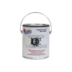
Conventional cleaning methods like throttle body cleaner aren’t very effective. The best method is a soak type cleaner used for carburetors. If you are into fixing motorcycles, jet skis, snowmobiles or anything else with a small carburetor, you probably have used the one gallon soak cleaners like Gunk or Berryman. One of the two should be available at your local auto parts store for $22-$29. There is a basket to set the parts in while they are soaking. Soak the metal body in the carb cleaner overnight. Don’t immerse the diaphragm side, since the carb cleaner may damage the diaphragm. If you get any of the carb cleaner on the diaphragm, rinse it off with water immediately. Rinse the part off with water and blow it dry with compressed air. Once it has dried, try blowing through the either hole and it should block the air flow. Do not put parts with water on them or in them in the carb cleaner. If you do, it will weaken the carb cleaner and it won’t clean as effectively.
Gunk Dip type carb & parts soaker:
If you have a handy vacuum source, apply it to the diaphragm and watch to see if the pintle moves freely. Try blowing air through either side and make sure it flows when the pintle retracts and blocks when the pintle is seated. If it does not, replace the EGR.
If the blow by test passes, and you have replaced the sensor, then you have electrical ground problems. Check the resistance between the black/white wire on the MAP/BARO sensor and then the black/white wire on the EGR and the same wire on the TPS. It should be less than 1.5 ohm. Next check the resistance between the black/white wire and the negative battery post. It should be less than 1.5 ohm.
Note that all resistance tests must be done with power off. Measuring resistance with a circuit powered on will give false readings and possibly damage the meter.
Let’s put on our Inspector Gadget propeller head beanies and think about how this works:
The EGR sensor is a variable resistor with ground on one leg and Vref (5 volts) on the other. Its’ resistance ranges from 4000 to 5500 Ohms measured between Vref & ground, depending on the sensor. The center connection of the variable resistor is the slider that moves in response to the amount of vacuum applied. The slider has some minimum value of resistance greater than 100 ohms so that the computer always sees a voltage present at its’ input. If the value was 0 ohms, there would be no voltage output. Then the computer would not be able to distinguish between a properly functioning sensor and one that had a broken wire or bad connection. The EGR I have in hand reads 700 Ohms between the slider (EPV) and ground (SIG RTN) at rest with no vacuum applied. The EGR valve or sensor may cause the voltage to be above closed limits due to the manufacturing tolerances that cause the EGR sensor to rest at a higher position than it should.
The following sensors are connected to the white 10 pin connector (salt & pepper engine harness connectors)
This will affect idle quality by diluting the intake air charge
Code 41 or 91. Or 43 Three digit code 172 or 176 - O2 sensor indicates system lean. Look for a vacuum leak or failing O2 sensor.
Revised 6-Oct-2014 to improve code 41 description due to clogged Thermactor air crossover tube
Code 41 is a RH side sensor, as viewed from the driver's seat.
Code 91 is the LH side sensor, as viewed from the driver's seat.
Code 172 is the RH side sensor, as viewed from the driver's seat.
Code 176 is the LH side sensor, as viewed from the driver's seat.
Code 43 is not side specific according to the Probst Ford Fuel injection book.
The computer sees a lean mixture signal coming from the O2 sensors and tries to compensate by adding more fuel. Many times the end result is an engine that runs pig rich and stinks of unburned fuel.
The following is a Quote from Charles O. Probst, Ford fuel Injection & Electronic Engine control:
"When the mixture is lean, the exhaust gas has oxygen, about the same amount as the ambient air. So the sensor will generate less than 400 Millivolts. Remember lean = less voltage.
When the mixture is rich, there's less oxygen in the exhaust than in the ambient air , so voltage is generated between the two sides of the tip. The voltage is greater than 600 millivolts. Remember rich = more voltage.
Here's a tip: the newer the sensor, the more the voltage changes, swinging from as low as 0.1 volt to as much as 0.9 volt. As an oxygen sensor ages, the voltage changes get smaller and slower - the voltage change lags behind the change in exhaust gas oxygen.
Because the oxygen sensor generates its own voltage, never apply voltage and never measure resistance of the sensor circuit. To measure voltage signals, use an analog voltmeter with a high input impedance, at least 10 megohms. Remember, a digital voltmeter will average a changing voltage." End Quote
Testing the O2 sensors 87-93 5.0 Mustangs
Measuring the O2 sensor voltage at the computer will give you a good idea of how well they are working. You'll have to pull the passenger side kick panel off to gain access to the computer connector. Remove the plastic wiring cover to get to the back side of the wiring. Use a safety pin or paper clip to probe the connections from the rear.
Disconnect the O2 sensor from the harness and use the body side O2 sensor harness as the starting point for testing. Do not measure the resistance of the O2 sensor , you may damage it. Resistance measurements for the O2 sensor harness are made with one meter lead on the O2 sensor harness and the other meter lead on the computer wire or pin for the O2 sensor.
Backside view of the computer wiring connector:
87-90 5.0 Mustangs:
Computer pin 43 Dark blue/Lt green – LH O2 sensor
Computer pin 29 Dark Green/Pink – RH O2 sensor
The computer pins are 29 (L\RH O2 with a dark green/pink wire) and 43 (LH O2 with a dark blue/pink wire). Use the ground next to the computer to ground the voltmeter. The O2 sensor voltage should switch between .2-.9 volt at idle.
91-93 5.0 Mustangs:
Computer pin 43 Red/Black – LH O2 sensor
Computer pin 29 Gray/Lt blue – RH O2 sensor
The computer pins are 29 (LH O2 with a Gray/Lt blue wire) and 43 (RH O2 with a Red/Black wire). Use the ground next to the computer to ground the voltmeter. The O2 sensor voltage should switch between .2-.9 volt at idle.
Testing the O2 sensors 94-95 5.0 Mustangs
Measuring the O2 sensor voltage at the computer will give you a good idea of how well they are working. You'll have to pull the passenger side kick panel off to gain access to the computer connector. Remove the plastic wiring cover to get to the back side of the wiring. Use a safety pin or paper clip to probe the connections from the rear. The computer pins are 29 (LH O2 with a red/black wire) and 27 (RH O2 with a gray/lt blue wire). Use pin 32 (gray/red wire) to ground the voltmeter. The O2 sensor voltage should switch between .2-.9 volt at idle.
Note that all resistance tests must be done with power off. Measuring resistance with a circuit powered on will give false readings and possibly damage the meter. Do not attempt to measure the resistance of the O2 sensors, it may damage them.
Testing the O2 sensor wiring harness
Most of the common multimeters have a resistance scale. Be sure the O2 sensors are disconnected and measure the resistance from the O2 sensor body harness to the pins on the computer. Using the Low Ohms range (usually 200 Ohms) you should see less than 1.5 Ohms.
87-90 5.0 Mustangs:
Computer pin 43 Dark blue/Lt green – LH O2 sensor
Computer pin 29 Dark Green/Pink – RH O2 sensor
Disconnect the connector from the O2 sensor and measure the resistance:
From the Dark blue/Lt green wire in the LH O2 sensor harness and the Dark blue/Lt green wire on the computer pin 43
From the Dark Green/Pink wire on the RH Os sensor harness and the Dark Green/Pink wire on the computer pin 29
91-93 5.0 Mustangs:
Computer pin 43 Red/Black – LH O2 sensor
Computer pin 29 Gray/Lt blue – RH O2 sensor
Disconnect the connector from the O2 sensor and measure the resistance:
From the Red/Black wire in the LH O2 sensor harness and the Red/Black wire on the computer pin 43
From the Dark Green/Pink Gray/Lt blue wire on the RH Os sensor harness and the Gray/Lt blue wire on the computer pin 29
94-95 5.0 Mustangs:
Computer pin 29 Red/Black – LH O2 sensor
Computer pin 27 Gray/Lt blue – RH O2 sensor
From the Red/Black wire in the LH O2 sensor harness and the Red/Black wire on the computer pin 29
From the Dark Green/Pink Gray/Lt blue wire on the RH Os sensor harness and the Gray/Lt blue wire on the computer pin 27
There is a connector between the body harness and the O2 sensor harness. Make sure the connectors are mated together, the contacts and wiring are not damaged and the contacts are clean and not coated with oil.
The O2 sensor ground (orange wire with a ring terminal on it) is in the wiring harness for the fuel injection wiring. I grounded mine to one of the intake manifold bolts
Make sure you have the proper 3 wire O2 sensors. Only the 4 cylinder cars used a 4 wire sensor, which is not compatible with the V8 wiring harness.
Replace the O2 sensors in pairs if replacement is indicated. If one is weak or bad, the other one probably isn't far behind.
Code 41 can also be due to carbon plugging the driver’s side Thermactor air crossover tube on the back of the engine. The tube fills up with carbon and does not pass air to the driver’s side head ports. This puts an excess amount of air in the passenger side exhaust and can set the code 41. Remove the tube and clean it out so that both sides get good airflow: this may be more difficult than it sounds. You need something like a mini rotor-rooter to do the job because of the curves in the tube. Something like the outer spiral jacket of a flexible push-pull cable may be the thing that does the trick.
If you get only code 41 and have changed the sensor, look for vacuum leaks. This is especially true if you are having idle problems. The small plastic tubing is very brittle after many years of the heating it receives. Replace the tubing and check the PVC and the hoses connected to it.
Fix the codes and then do a cylinder balance test if the engine does not run smoothly.
Cylinder balance test: use this to find dead or weak cylinders:
Revised 25 March 2012 to add necessity allowing the KOEO tests to finish before starting the engine and the need for a properly functioning IAB/IAC to run the cylinder balance test.
The computer has a cylinder balance test that helps locate cylinders with low power output. You’ll need to dump the codes out of the computer and make sure that you have the A/C off, clutch depressed to the floor and the transmission in neutral. Fail to do this and you can’t do the engine running dump codes test that allows you to do the cylinder balance test.
Here's the way to dump the computer codes with only a jumper wire or paper clip and the check engine light, or test light or voltmeter. I’ve used it for years, and it works great. You watch the flashing test lamp or Check Engine Light and count the flashes.
Be sure to turn off the A/C clutch depressed to the floor, and put the transmission in neutral when dumping the codes. Fail to do this and you will generate a code 67 and not be able to dump the Engine Running codes.
Here's how to dump the computer codes with only a jumper wire or paper clip and the check engine light, or test light or voltmeter. I’ve used it for years, and it works great. You watch the flashing test lamp or Check Engine Light and count the flashes.
If your car is an 86-88 stang, you'll have to use the test lamp or voltmeter method. There is no functional check engine light on the 86-88's except possibly the Cali Mass Air cars.
The STI has a gray connector shell and a white/red wire. It comes from the same bundle of wires as the self test connector.
89 through 95 cars have a working Check Engine light. Watch it instead of using a test lamp.
The STI has a gray connector shell and a white/red wire. It comes from the same bundle of wires as the self test connector.
WARNING!!! There is a single dark brown connector with a black/orange wire. It is the 12 volt power to the under the hood light. Do not jumper it to the computer test connector. If you do, you will damage the computer.
What to expect:
You should get a code 11 (two single flashes in succession). This says that the computer's internal workings are OK, and that the wiring to put the computer into diagnostic mode is good. No code 11 and you have some wiring problems.
This is crucial: the same wire that provides the ground to dump the codes provides signal ground for the TPS, EGR, ACT and Map/Baro sensors. If it fails, you will have poor performance, economy and drivability problems
Some codes have different answers if the engine is running from the answers that it has when the engine isn't running. It helps a lot to know if you had the engine running when you ran the test.
Dumping the Engine Running codes: The procedure is the same, you start the engine with the test jumper in place. Be sure the A/C is off, clutch depressed to the floor and the transmission is in neutral. You'll get an 11, then a 4 and the engine will speed up to do the EGR test. After the engine speed decreases back to idle, it will dump the engine running codes.
Trouble codes are either 2 digit or 3 digit, there are no cars that use both 2 digit codes and 3 digit codes.
Cylinder balance test
If you have idle or IAC/IAB problems and the engine will not idle on its own without mechanically adjusting the base idle speed above 625-750 RPM, this test will fail with random cylinders pointed out every time it runs. The IAC/IAB
must be capable of controlling the engine speed to run in the 1400-1600 RPM range. Playing with the base idle speed by adjusting it upwards will not work, the computer has to be able to control the engine speed using the IAC/IAB.
Warm the car's engine up to normal operating temperature. Use a jumper wire or paper clip to put the computer into test mode. Let it finish the Key On Engine Off (KOEO) code dump. Start the engine and let it go through the normal diagnostic tests, then quickly press the throttle to the floor. Remember to keep the clutch pedal (5 speed) depressed to the floor during the test. The engine RPM should exceed 2500 RPM's for a brief second. The engine RPM's will increase to about 1450-1600 RPM and hold steady. The engine will shut off power to each injector, one at a time. When it has sequenced through all 8 injectors, it will flash 9 for everything OK, or the number of the failing cylinder such as 2 for cylinder #2. Quickly pressing the throttle again up to 2500 RPM’s will cause the test to re-run with smaller qualifying figures.
Do it a third time, and if the same cylinder shows up, the cylinder is weak and isn’t putting out power like it should. See the Chilton’s Shop manual for the complete test procedure
Do a compression test on all the cylinders.
Take special note of any cylinder that shows up as weak in the cylinder balance test. Low compression on one of these cylinders rules out the injectors as being the most likely cause of the problem. Look at cylinders that fail the cylinder balance test but have good compression. These cylinders either have a bad injector, bad spark plug or spark plug wire. Move the wire and then the spark plug to another cylinder and run the cylinder balance test again. If it follows the moved wire or spark plug, you have found the problem. If the same cylinder fails the test again, the injector is bad. If different cylinders fail the cylinder balance test, you have ignition problems or wiring problems in the 10 pin black & white electrical connectors located by the EGR.
How to do a compression test:
Only use a compression tester with a screw in adapter for the spark plug hole. The other type leaks too much to get an accurate reading. Your local auto parts store may have a compression tester to rent/loan. If you do mechanic work on your own car on a regular basis, it would be a good tool to add to your collection.
With the engine warmed up, remove all spark plugs and prop the throttle wide open with a plastic screwdriver handle between the throttle butterfly and the throttle housing. Crank the engine until it the gage reading stops increasing. On a cold engine, it will be hard to tell what's good & what's not. Some of the recent posts have numbers ranging from 140-170 PSI. If the compression is low, squirt some oil in the cylinder and do it again – if it comes up, the rings are worn. There should be no more than 10% difference between cylinders. Use a blow down leak test (puts compressed air inside cylinders) on cylinders that have more than 10% difference.
I generally use a big screwdriver handle stuck in the TB between the butterfly and the TB to prop the throttle open. The plastic is soft enough that it won't damage anything and won't get sucked down the intake either.
A battery charger (not the trickle type) is a good thing to have if you haven't driven the car lately or if you have any doubts about the battery's health. Connect it up while you are cranking the engine and it will help keep the starter cranking at a consistent speed from the first cylinder tested to the last cylinder.