no fuel to motor yet the sparks fine (2.3 to 5.0 swap)

NFGTragedy

New Member
Oct 19, 2004
155
0
0
Rochester, NY
I've had this problem ever since i completed my 5.0l swap from 2.3l... The fuel pump doesn't turn on when ignition is in the on position or starting position ( tested for no pressure at fuel rails) yet the motor sparks just fine in start position.. attempts to start, crank turns... whole deal.

I have been at college all year and I just returned to finish my project... tomorrow will be my first day tackling it again... just want some pointers while i try and find where its failing.

-car details-
current car 89 lx
motor/tranny/fuel tank/ecu from 91 gt
motor harness from 89 gt ( switched when i realized the difference )

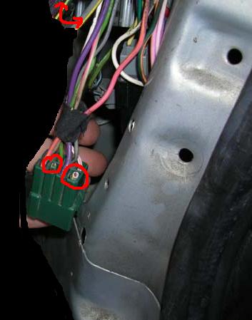
I have heard the inertia switch is something to check but last time i checked it, it seemed to be fine (last year). I have heard things such that it could be the fuel pump itself just not working but i doubt it since it came from a car that was t-boned so i assume it was running at time of impact. I also made sure the connector to the fuel pump was securely fastened. At the time of the swap I accidently lost track of the wires that go on the two terminals... some sort of power distrubtor (drivers side next to the coil). I followed a book to put them back so i assume they are right.. but maybe not? Also when I was doing the heater core swap... which btw is a fun project... i ended up messing up the ignition switch that mounts to the key cylinder.. its a small white box (mounted on an angle)... but since I had a parts car that i stripped i went over and found the gt one which was laying outside and put that in... needless to say last time i checked the electric windows and mirrors which failed to work also... post-swap problem, possibly a related problem?

now... does this switch(ignition) go bad if it gets wet or sits outside for sayyyy 8 months :) ?... if so how can i test if it to prove that it is my problem? Also any other tips to check along the way... i have heard to check voltages along the wire to the fuel system... ie ( under the drivers side seats before/after, inertia switch before/after, wire to pump )... anyone know what the normal voltage ratings should be there?

anything else i should check before i go crazy following wires all over? any ideas??
 
  • Sponsors (?)


I remember there was some relay near the ECU I had to swap when I did mine. I think it was green in color or the connectors were and it was fuel related. It was up by the passenger dash speaker. Did you get that one switched too? Sorry I don't remember clearly...
 
I don't remember exactly but for some reason I did mine and I kept the swap as minimal as possible. It might be worth a shot but it sounds like you have some other issues too. The best advice is to start with the easy, cheap stuff first then move on from there. Good luck this summer
 
yeah thanks for the idea... not something i would have thought to try out. For some reason I think its that ignition switch. My original one broke in two when the steering wheel was lowered for the heater core... I really hope none of the wires broke during that accident... never checked really... but if something is funky with that switch maybe it could be why my windows/mirrors don't work?
 
Fuel Pump Troubleshooting for 86-90 Mustangs

Clue – listen for the fuel pump to prime when you first turn the ignition switch on.
It should run for 5-20 seconds and shut off. To trick the fuel pump into running,
find the ECC test connector and jump the connector in the lower RH corner to
ground.
attachment.php

If the fuse links are OK, you will have power to the pump. Check fuel pressure –
remove the cap from the Schrader valve behind the alternator and depress the
core. Fuel should squirt out, catch it in a rag. A tire pressure gauge can also be
used if you have one - look for 37-40 PSI. Beware of fire hazard when you do this.

No fuel pressure, possible failed items in order of their probability:
A.) Tripped inertia switch – press reset button on the inertia switch. The hatch
cars hide it under the plastic trim covering the driver's side taillight. Use the
voltmeter or test light to make sure you have power to both sides of the switch

B.) Fuel pump power relay – located under the driver’s seat in most stangs built
before 92. On 92 and later model cars it is located below the Mass Air Flow meter.
C.) Clogged fuel filter
D.) Failed fuel pump
E.) Blown fuse link in wiring harness.
F.) Fuel pressure regulator failed. Remove vacuum line from regulator and inspect
for fuel escaping while pump is running.

The electrical circuit for the fuel pump has two paths, a control path and a power
path.

The control path consists of the inertia switch, the computer, and the fuel pump
relay coil. It turns the fuel pump relay on or off under computer control. The
switched power (red wire) from the ECC relay goes to the inertia switch
(red/black wire) then from the inertia switch to the relay coil and then from the
relay coil to the computer (tan/ Lt green wire). The computer provides the ground
path to complete the circuit. This ground causes the relay coil to energize and
close the contacts for the power path. Keep in mind that you can have voltage
to all the right places, but the computer must provide a ground. If there is no
ground, the relay will not close the power contacts.

The power path picks up from a fuse link near the starter relay. Fuse links are like
fuses, except they are pieces of wire and are made right into the wiring harness.
The feed wire from the fuse link (orange/ light blue wire) goes to the fuel pump
relay contacts. When the contacts close because the relay energizes, the power
flows through the contacts to the fuel pump (light pink/black wire). The fuel pump
has a black wire that supplies the ground to complete the circuit.

Remember that the computer does not source any power to actuators, relays
or injectors, but provides the ground necessary to complete the circuit. That
means one side of the circuit will always be hot, and the other side will go to
ground or below 1 volt as the computer switches on that circuit.


See the following website for some help from Tmoss (diagram designer) &
Stang&2Birds (website host)

http://www.veryuseful.com/mustang/tech/engine/images/IgnitionSwitchWiring.gif

http://www.veryuseful.com/mustang/tech/engine/images/fuel-alt-links-ign-ac.gif

http://www.veryuseful.com/mustang/tech/engine/images/88-91eecPinout.gif

Diagram courtesy of Tmoss & Stang&2birds

fuel-alt-links-ign-ac.gif


Now that you have the theory of how it works, it’s time to go digging.

Look for 12 volts at the Orange/Lt. Blue wire (power source for fuel pump relay).
No voltage or low voltage, bad fuse link, bad wiring, bad ignition switch or ignition
switch wiring or connections. There is a mystery connector somewhere under the
driver’s side kick panel, between the fuel pump relay and the fuse link.

Turn on the key and jumper the fuel pump test connector to ground as previously
described. Look for 12 volts at the Light Pink/Black wire (relay controlled power
for the fuel pump). No voltage there means that the relay has failed, or there is a
broken wire in the relay control circuit.

Check the Red/black wire, it should have 12 volts. No 12 volts there, either the
inertia switch is open or has no power to it. Check both sides of the inertia
switch: there should be power on the Red wire and Red/Black wire. Power on the
Red wire and not on the Red/Black wire means the inertia switch is open.

The Tan/Lt Green wire provides a ground path for the relay power. With the test
connector jumpered to ground, there should be less than .75 volts. Use a test
lamp with one side connected to battery power and the other side to the
Tan/Lt Green wire. The test light should glow brightly. No glow and you have a
broken wire or bad connection between the test connector and the relay. To test
the wiring from the computer, remove the passenger side kick panel and
disconnect the computer connector. It has a 10 MM bolt that holds it in place.
With the test lamp connected to power, jumper pin 22 to ground and the test
lamp should glow. No glow and the wiring between the computer and the fuel
pump relay is bad.

If all of the checks have worked OK to this point, then the computer is bad. The
computers are very reliable and not prone to failure unless there has been
significant electrical trauma to the car. Things like lightning strikes and putting
the battery in backwards or connecting jumper cables backwards are about the
only thing that kills the computer.
 
I've been following this complaint on a few swaps...and I'm waiting for my time

I'm at the very end of my swap, expect to be done this weekend??

well I've searched many threads over the past year doing research and found many people with this complaint about the fuel pump not running...

here's a solution I've READ but not tried yet:

MrKwik said:
quote from here: http://forums.stangnet.com/showthread.php?t=557489

For one, I wouldnt suggest using the 2.3 EFI pump. But as far as not coming on....did you remove the computer and EFI harness when you swappen in the 5.0? If you did, you would have to do some creative rewiring to get the fuel pump to run. The easy way is to just splice 2 wires together in the passenger kick panel where the computer used to be. I can tell you exactly which wires but it will have to wait till I get home this evening. I made wiring diagrams when I rewired my 4cyl to 5.0 cars. There is a green and a grey connector in the kick that have the wires you need. You just splice a "hot in run" wire to the fuel pump wire. I think the hot in run wire is grey/yellow and I'm thinking that the wire that goes back to the inertia switch is red/blue but dont hold me to that. I personally like to wire in a relay and oil pressure switch so that the pump doesnt run if the engine isnt running but it isnt totally required.


OK, I have the correct wire colors now. The "hot in run" wire is grey with a yellow stripe. The wire to the fuel pump inertia switch is dk green with a yellow stripe. They are both located in the passenger side kick panel by the ECM in the green 8-pin connector. I Always wire in a relay and an oil pressure switch but you can just solder and shring them together and the pump will run whenever the key is in the IGN posistion.

I know this is correct for 91-93 but you didnt say what year your car is so if its older I suppose there is a possibility the wire codes could be different.
Attached Thumbnails

attachment.php

I wasn't going to do the relay..I was just going to splice the two wires together...like this:
fuelwiring.JPG


...I'm going to do nothing until I try to crank it over and see if I have the problem...if I do I plant to splice those two wires together. I'll plan to leave some extra off the plug incase it was the wrong move...
 
I've done a few of these swaps and never had any problems since i've used the correct year harness for the cars.

Although my buddy who has done a couple himself, doesn't match the harness to the year of the car. But hey, he's a ford tech specializing in electrical...lol. Every one the fuel pump doesn't work and he runs a jumper wire.
 
I wonder if later model foxes has something to do with it 91-93?
I can say I had the following
93 4 banger (automatic)
93 computer from an AOD car
93 Engine harness and headlight harness

all from the year 93

I know for a fact that the 90 year is a stand alone year (so all years must match in this case) 91-93 cars can be mixed- but I match it all to play it as close as possible (and I still had to do this splice for the fuel pump)

I changed everything including the fuel pump, computer, wiring as described and even used the 93 guage cluster from the 5.0 donor car.

hope this helps anyone in the future doing this swap, I know finding the previous post by mr kirk saved me hours of agravation, I solved the problem in 3 seconds having read about it ahead of time. (and I did wait until I actually had the problem before spicing the wires to make sure it would even be an issue for me)
 
From what i've noticed in doing this...not saying its 100% accurate.

89 is the only year you really want to stay 89 harness(can be used on 87-88 if changing to mass air)....only mass air non air bag.

90-early 92 are interchangeable...2 plugs...one black,one gray

late 92 and 93 use the single brown plug.

Headlight/alternator harness has nothing to do with it...only affects the alternator charging.
 
I wanted to follow up on this thread,

I had a constant power that was grounded isntead of getting constat power which prevented the red power wire circuit from getting constant power, It took me a few days to fix it.

so; now that I fixed it, I wondered...would my fuel pump work the ORIGINAL WAY...and guess what...it does!

I didn't need to wire it that other way after all, It seemed to bypass the relay or something in the engine harness that wasn't working originally because of a constant power was grounded instead of on the starter relay.

hope this helps someone in the future

all my wires, car and computer were 93
 
ok, so running the wires the "stock method" I had some issues...it worked fine for 2 days, and then one day the fuel pump did not come on out of the blue....and then it magically was working again...I drove a bit and it died stopped working going down the road..and then it worked again...

so for the time being I wired it back the way I had it (spliced as described above which I image bypasses the relay and maybe even teh computer?)

my question, until I figure out what's wrong, can i leave it spliced this way without major concern? does it hurt to have the pump running more than it should? it only runs in the run postion, so it's not running when the car is off.

and would a fuel pump relay be an issue if the problem was there but not there and there again? I assume if it was the relay then it would just not work at all?
 
This may help with the fuel pump. Being your car is a cross, I cannot be sure the wire colors are the same as the tech note.

Fuel Pump Troubleshooting for 91-93 Mustangs

Clue – listen for the fuel pump to prime when you first turn the ignition switch on.
It should run for 5-20 seconds and shut off. To trick the fuel pump into running,
find the ECC test connector and jump the connector in the lower RH corner to
ground.
attachment.php

If the fuse links are OK, you will have power to the pump. Check fuel pressure –
remove the cap from the Schrader valve behind the alternator and depress the
core. Fuel should squirt out, catch it in a rag. A tire pressure gauge can also be
used if you have one - look for 37-40 PSI. Beware of fire hazard when you do this.


No fuel pressure, possible failed items in order of their probability:
A.) Tripped inertia switch – press reset button on the inertia switch. The hatch
cars hide it under the plastic trim covering the driver's side taillight. Use the
voltmeter or test light to make sure you have power to both sides of the switch

B.) Fuel pump power relay – located under the driver’s seat in most stangs built
before 92. On 92 and later model cars it is located below the Mass Air Flow meter.

C.) Clogged fuel filter
D.) Failed fuel pump
E.) Blown fuse link in wiring harness.
F.) Fuel pressure regulator failed. Remove vacuum line from regulator and inspect
for fuel escaping while pump is running.

The electrical circuit for the fuel pump has two paths, a control path and a power
path.

The control path consists of the computer, and the fuel pump relay coil. It turns
the fuel pump relay on or off under computer control. The switched power (red
wire) from the ECC relay goes to the relay coil and then from the relay coil to the
computer (light blue\orange wire). The computer provides the ground path to
complete the circuit. This ground causes the relay coil to energize and close the
contacts for the power path. Keep in mind that you can have voltage to all the
right places, but the computer must provide a ground. If there is no ground, the
relay will not close the power contacts.

The power path picks up from a fuse link near the starter relay. Fuse links are like
fuses, except they are pieces of wire and are made right into the wiring harness.
The feed wire from the fuse link (pink/black wire) goes to the fuel pump relay
contacts. When the contacts close because the relay energizes, the power flows
through the pink/black wire to the contacts and through the dark green\yellow
wire to the inertia switch. The other side of the inertia switch with the
brown\pink wire joins the pink/black wire that connects to the fuel pump. The fuel
pump has a black wire that supplies the ground to complete the circuit.

Remember that the computer does not source any power to actuators, relays
or injectors, but provides the ground necessary to complete the circuit. That
means one side of the circuit will always be hot, and the other side will go to
ground or below 1 volt as the computer switches on that circuit.


0900823d80195960.gif

diagram of the wiring for 91-93 cars.

Power circuits:
Power feed: Look for 12 volts at the pink/black wire (power source for fuel pump relay).
No voltage or low voltage, bad fuse link, bad wiring, or connections. Remember that on 92
or later models the fuel pump relay is located under the Mass Air meter. Watch out for the
WOT A/C control relay on these cars, as it is located in the same place and can easily be
mistaken for the fuel pump relay.

Relay: Turn on the key and jumper the ECC test connector as previously described. Look
for 12 volts at the dark green\yellow wire (relay controlled power for the fuel pump). No
voltage there means that the relay has failed, or there is a broken wire in the relay control circuit.

Inertia switch: Check the brown/pink wire, it should have 12 volts. No 12 volts there, either
the inertia switch is open or has no power to it. Check both sides of the inertia switch: there
should be power on the dark green\yellow (inertia switch input) and brown/pink wire
(inertia switch output). Power on the dark green\yellow wire and not on the brown/pink wire
means the inertia switch is open. Press on the red plunger to reset it to the closed position.
Sometimes the inertia switch will be intermittent or will not pass full power. Be sure that
there is 12 volts on both sides of the switch with the pump running and that the voltage drop
measured across the switch is less than .75 volts.

Control circuits:

Relay: The red wire for the fuel pump relay coil gets its power feed from the ECC relay.
No 12 volts here, and the ECC relay has failed or there is bad wiring or bad connections
coming from it. The ECC relay is located on top of the computer, which is under the passenger’s
side kick panel. It is not easy to get to, you must have small hands or pull the passenger side
dash speaker out to access it.

Relay: The light blue/orange wire provides a ground path for the relay power. With the test
connector jumpered according to the previous instructions, there should be less than .75 volts.
Use a test lamp with one side connected to battery power and the other side to the light blue/orange
wire on the fuel pump relay. The test light should glow brightly. No glow and you have a broken
wire or bad connection between the test connector and the relay. To test the wiring from the
computer, remove the passenger side kick panel and disconnect the computer connector.
It has a 10 MM bolt that holds it in place. Remove the test jumper from the ECC test connector.
With the test lamp connected to power, jumper pin 22 to ground and the test lamp should glow.
No glow and the wiring between the computer and the fuel pump relay is bad.

Computer: If you got this far and everything else checked out good, the computer is suspect .
Remove the test jumper from the ECC test connector located under the hood . Remove the
plastic cover over the computer wiring, but leave the computer wiring connector plugged
into the computer. With the ignition switch in the run position, connect a test lamp to the
battery and back probe pin 22, the light blue/orange wire with it. The lamp should glow
brightly. No glow and the computer has died a sad death. :( If you used a voltmeter instead
of a test lamp, you should see battery voltage, whatever that may be…

See the following website for some help from Tmoss (diagram designer) & Stang&2Birds (website host) for help on 88-95 wiring http://www.veryuseful.com/mustang/tech/engine/

http://www.veryuseful.com/mustang/tech/engine/images/IgnitionSwitchWiring.gif

http://www.veryuseful.com/mustang/tech/engine/images/fuel-alt-links-ign-ac.gif

http://www.veryuseful.com/mustang/tech/engine/images/88-91eecPinout.gif

Fuel pump runs continuously: The light blue/orange wire has shorted to ground. Disconnect
the computer and use an ohmmeter to check out the resistance between the light blue/orange
wire and ground. You should see more than 10 K Ohms (10,000 ohms) or an infinite open
circuit. Be sure that the test connector isn’t jumpered to ground.
 
fuel pump stays on

i had the swap done and had issues with pump .the solution was it wasn't getting power.so they ran a new wire with a fuse in it .but my pump stays on all the time is this right.i read it should turn off after 5 to 10 seconds would this create a rich smell out of exhaust.:mad:
 
bluidvl said:
i had the swap done and had issues with pump .the solution was it wasn't getting power.so they ran a new wire with a fuse in it .but my pump stays on all the time is this right.i read it should turn off after 5 to 10 seconds would this create a rich smell out of exhaust.:mad:
Not having any idea of what was done and how it was done, it is difficult to say what is happening. Your car is listed as a 90 model, which means the wiring is probably different from the wiring in the 91-93 model tech note I posted.
 
re-wring the pump power was kind what I did, though I'm trying to figure out the gray w/ yellow stripe wire and why splicing to the green w/ yellow stripe allow it to work....

I'm trying to make it so mine works the stock method because I'm also concerned about it running more/longer than it should
 
Nicoleb3x3 said:
re-wring the pump power was kind what I did, though I'm trying to figure out the gray w/ yellow stripe wire and why splicing to the green w/ yellow stripe allow it to work....

I'm trying to make it so mine works the stock method because I'm also concerned about it running more/longer than it should
From the diagram in the tech note I posted:
The wire colors & functions are for a 91-93 model car. Please post the year model if this is not correct. It is possible that the body harness and engine harness are different years. That would cause a color mismatch for some of the wires.

Gray/yellow - pin 31, canister purge circuit. It switches to ground like the fuel pump relay control. However it does it at a different time.

Green/yellow - pin 25, ACT sense. Miswire this and the ACT quits working properly. You would get a code 24 or code 64 if is is miswired.
 
Nicoleb3x3 said:
...wired, I'm not getting any codes...or at least the check engine light is not comming on?

and the chassis and engine harness and computer are all 93.
The computer will generate codes without setting the Check Engine Light. I recommend that you try to dump the codes and see what the computer says is wrong…

Here's the link to dump the computer codes with only a jumper wire or paper clip and the check engine light, or test light or voltmeter. I’ve used it for years, and it works great.

See http://www.troublecodes.net/Ford/
OR
See http://www.mustangworks.com/articles/electronics/eec-iv_codes.html

IF your car is an 86-88 stang, you'll have to use the test lamp or voltmeter method. There is no functional check engine light on the 86-88's except possibly the Cali Mass Air cars.

Codes have different answers if the engine is running from the answers that it has when the engine isn't running. It helps a lot to know if you had the engine running when you ran the test.

Trouble codes are either 2 digit or 3 digit, there are no cars that use both 2 digit codes and 3 digit codes.

For those who are intimidated by all the wires & connections, see http://www.actron.com/product_detail.php?pid=16153 for what a typical hand scanner looks like. Normal retail price is about $30 or so at AutoZone or Walmart.

Or for a nicer scanner see http://www.midwayautosupply.com/detailedproductdescription.asp?3829 – It has a 3 digit LCD display so that you don’t have to count flashes or beeps.. Cost is $35.