code 98 and 51, what do these mean? Please help!

v8only

Active Member
Jul 3, 2003
2,378
22
49
This is on my bro's car, an 86 ttop mustang with a 96 gt40 explorer motor, tfs stage 1 cam and a mass air conversion

98 - hard fault
51 - something about ecm voltage or something I don't know.

any ideas?

Car is stalling like crzy and won't idle. It didn't always do this after the install, but Sat night after a trip to the drag strip and 10 passes this started to happen.
 
  • Sponsors (?)


Jeremy, knowing when the code was spit (EO, ER, etc) will help.

98 could just be that you're in FMEM [if it's KOER]. If EO, it is the puter-issue you mentioned (and Jrichker can let ya know what that actually means).

51 should be related to ECT I think. It can be the Power steering switch but I don't know that we have one (since we don't compensate for PS load).

Others will know a lot more, but I figured I'd post what little I know.

Good luck buddy.
 
Code 51 Engine Coolant Temperature (ECT) sensor signal is/was too high -
Possible bad ECT sensor, or wiring. Possible missing signal ground –
black/wire wire broken or bad connection. With the power off, measure the
resistance between the black/white wire and battery ground. You should see
less than 1.5 ohm. Check the same black /white wire on the TPS and MAP
sensor. More than 1.5 ohm there and the wire is probably broken in the harness
between the engine and the computer. The 10 pin connectors pass the
black/white wire back to the computer, and can cause problems.

Pin 7 on the computer - ECT signal in. at 176 degrees F it should be .80 volts

Voltages may be measured across the ECT by probing the connector from the rear.
Use care in doing it so that you don't damage the wiring or connector.

Here's the table :

68 degrees F = 3.02 v
86 degrees F = 2.62 v
104 degrees F = 2.16 v
122 degrees F = 1.72 v
140 degrees F = 1.35 v
158 degrees F = 1.04 v
176 degrees F = .80 v
194 degrees F = .61

Note that all resistance tests must be done with power off. Measuring resistance
with a circuit powered on will give false readings and possibly damage the meter.


Ohms measures at the computer with the computer disconnected, or at the sensor with
the sensor disconnected.
50 degrees F = 58.75 K ohms
68 degrees F = 37.30 K ohms
86 degrees F = 27.27 K ohms
104 degrees F = 16.15 K ohms
122 degrees F = 10.97 K ohms
140 degrees F = 7.60 K ohms
158 degrees F = 5.37 K ohms
176 degrees F = 3.84 K ohms
194 degrees F = 2.80 K ohms

Diagram courtesy of Tmoss & Stang&2birds

88-91_5.0_EEC_Wiring_Diagram.gif


See the following website for some help from Tmoss (diagram designer) & Stang&2Birds (website host) for help on 88-95 wiring http://www.veryuseful.com/mustang/tech/engine/

http://www.veryuseful.com/mustang/tech/engine/images/IgnitionSwitchWiring.gif

http://www.veryuseful.com/mustang/tech/engine/images/fuel-alt-links-ign-ac.gif

http://www.veryuseful.com/mustang/tech/engine/images/88-91_5.0_EEC_Wiring_Diagram.gif


Code 98 - basic computer internal tests not passed before it started processing
the request to dump codes. Do a Key On Engine Off test before starting the engine.
Wait until you see the 11 flash before pressing any buttons if you have a hand
operated scanner. The computer is operating in Limp mode, so fix any codes it
dumps prior to doing anything else.
 
The codes were posted my 86 GT.

I was able to get 51 to clear, I was an idiot and was running a test with the engine cold. 51 and 98 both cleared.

I'm now getting 44 and 94 for thermactor left and thermactor right. Does this mean my tab and tad solenoids are bad?

I'm also getting 33 - egr opening not detected. Could this be a bad evp sensor on the back of the egr valve?
 
Code 33 - Insufficient EGR flow detected.
Look for vacuum leaks, cracked vacuum lines, failed EGR vacuum regulator. Check to see if you have 10” of vacuum at the EGR vacuum connection coming from the intake manifold. Look for electrical signal at the vacuum regulator solenoid valves located on the rear of the passenger side wheel well. Using a test light across the electrical connector, it should flicker as the electrical signal flickers. Remember that the computer does not source any power, but provides the ground necessary to complete the circuit. That means one side of the circuit will always be hot, and the other side will go to ground or below 1 volt as the computer switches on that circuit.
Check for resistance between the brown/lt green wire on the EGR sensor and pin 27 on the computer: you should have less than 1 ohm.

See the following website for some help from Tmoss (diagram designer) & Stang&2Birds (website host)

http://www.veryuseful.com/mustang/tech/engine/images/fuel-alt-links-ign-ac.gif

http://www.veryuseful.com/mustang/tech/engine/images/88-91eecPinout.gif


EGR test procedure courtesy of cjones

to check the EGR valve:
bring the engine to normal temp.
connect a vacuum pump to the EGR Valve
apply 5in vacuum to the valve.
if engine stumbled or died then EGR Valve and passage(there is a passageway through the heads and intake) are good.
if engine did NOT stumble or die then either the EGR Valve is bad and/or the passage is blocked.
if engine stumbled, connect vacuum gauge to the hose coming off of the EGR Valve
snap throttle to 2500 RPM (remember snap the throttle don't hold it there).
did the vacuum gauge show about 5in vacuum?

if not, check for manifold vacuum at the EGR vacuum valve.
if you have manifold vacuum then connect vacuum gauge to the EGR valve side of the vacuum valve and snap throttle to 2500 RPM.
should read about 5in vacuum

The operation of the EGR vacuum regulator can be checked by using a test light applied across the wiring connector. Jumper the computer into self test mode and turn the key on but do not start the engine. You will hear all the actuators (including the EVR vacuum regulator) cycle. Watch for the light to flicker: that means the computer has signaled the EGR vacuum regulator successfully.


Codes 94 & 44 - AIR system inoperative - Air Injection. Check vacuum lines for leaks, & cracks. Disconnect the big hose from smog pump: with the engine running you should feel air output. Reconnect the smog pump hose & apply vacuum to the first vacuum controlled valve: Its purpose is to either dump the pump's output to the atmosphere or pass it to the next valve. The next vacuum controlled valve directs the air to either the cylinder heads when the engine is cold or to the catalytic converter when the engine is warm. Disconnect the big hoses from the back side of the vacuum controlled valve and start the engine. Apply vacuum to the valve and see if the airflow changes from one hose to the next.
The two electrical controlled vacuum valves mounted on the rear of the passenger side wheelwell turn the vacuum on & off under computer control. Check to see that both valves have +12 volts on the red wire. Then ground the white/red wire and the first solenoid should open and pass vacuum. Do the same thing to the light green/black wire on the second solenoid and it should open and pass vacuum.

Remember that the computer does not source power for any actuator or relay, but provides the ground necessary to complete the circuit. That means one side of the circuit will always be hot, and the other side will go to ground or below 1 volt as the computer switches on that circuit.

The computer provides the ground to complete the circuit to power the solenoid valve that turns the vacuum on or off. The computer is located under the passenger side kick panel. Remove the kick panel & the cover over the computer wiring connector pins. Check Pin 38 Solenoid valve #1 that provides vacuum to the first Thermactor control valve for a switch from 12-14 volts to 1 volt or less. Do the same with pin 32 solenoid valve #2 that provides vacuum to the second Thermactor control valve. Starting the engine with the computer jumpered to self test mode will cause all the actuators to toggle on and off. If after doing this and you see no switching of the voltage on and off, you can start testing the wiring for shorts to ground and broken wiring. An Ohm check to ground with the computer connector disconnected & the solenoid valves disconnected should show open circuit between the pin 32 and ground and again on pin 38 and ground. In like manner, there should be less than 1 ohm between pin 32 and solenoid valve #2 and pin 38 & Solenoid valve #1.

If after checking the resistance of the wiring & you are sure that there are no wiring faults, start looking at the solenoid valves. If you disconnect them, you can jumper power & ground to them to verify operation. Power & ground supplied should turn on the vacuum flow, remove either one and the vacuum should stop flowing.
See the following website for some help from Tmoss (diagram designer) & Stang&2Birds (website host)

http://www.veryuseful.com/mustang/tech/engine/images/fuel-alt-links-ign-ac.gif

http://www.veryuseful.com/mustang/tech/engine/images/88-91eecPinout.gif


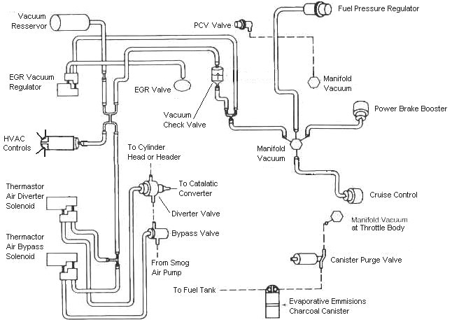
Look for vacuum system problems. Someone may have damaged or incorrectly connected some of the vacuum lines that work the EGR & smog pump systems.

mustangFoxFordVacuumDiagram.jpg
 
Codes 94 & 44 - AIR system inoperative - Air Injection. Check vacuum lines for leaks, & cracks.
Inspected vacuum lines, no cracks, none of them are broken.


Disconnect the big hose from smog pump: with the engine running you should feel air output. Reconnect the smog pump hose & apply vacuum to the first vacuum controlled valve: Its purpose is to either dump the pump's output to the atmosphere or pass it to the next valve. The next vacuum controlled valve directs the air to either the cylinder heads when the engine is cold or to the catalytic converter when the engine is warm. Disconnect the big hoses from the back side of the vacuum controlled valve and start the engine. Apply vacuum to the valve and see if the airflow changes from one hose to the next.

I verified air output from the smog pump. If you are facing the front of the car looking down on the passenger strut tower, there are the two tab/tad solenoids on the strut tower. The solenoid on the right(closest to engine) is switched on when the engine is running and supplies vacuum to the first vacuum solenoid on the air injection/smog pump hose assembly. When the engine is first started, the left tab/tad solenoid on the strut tower(furthest from engine) switches the other vacuum switch on the air injection setup, so that air passes through to the heads. After a minute or so, the vacuum switch starts to divert air down to the catalytic converters. So far, so good. Everything is working as you'd expect it to.

The two electrical controlled vacuum valves mounted on the rear of the passenger side wheelwell turn the vacuum on & off under computer control. Check to see that both valves have +12 volts on the red wire. Then ground the white/red wire and the first solenoid should open and pass vacuum. Do the same thing to the light green/black wire on the second solenoid and it should open and pass vacuum.
Both solenoids on the single bracket on the back of the strut tower have about 12.5 volts. When I ground the left solenoid on the strut tower(furthest from the engine), and the engine has already been running for awhile, the solenoid switches where the air gets diverted. It starts diverting it to the back of the heads. So far so good. It looks like the solenoids are switching property when I ground them out.

Okay, at this point you're probably wondering what the problem is.

When I start the car on a cold engine, it runs just fine and idles fine. The Tab/Tad solenoids are diverting air to the back of the heads. After the engine runs for a minute or so, air gets diverted to the cats and I don't experience any issues with the thermactor setup.

After I warm the engine up to normal operating temp, I shut the engine off and turn it back on. The first thing that happens is the car dies. I start it again and the idle is up and down, practically stalling. After about 20 seconds of watching the idle jump up and down, it finally starts to even out. While the idle is jumping up and down, air is getting passed to the back of the heads. After a little while, air gets diverted to the cats and the idle starts to settle down. At this point, while the car is idling and at a complete stand still, I hit the throttle and air will get diverted to the back of the heads right when I push down on the throttle. While I am accelerating, I can hear the smog pump start to divert air upstream. Keep in mind, all of this happens only after I restart the engine after it has been warmed up. Sometimes it's hard to tell but I believe the car smells like it's running lean at this point.

This is on my 86 GT with an explorer engine swap with a TFS1 cam and MAF. I have the fuel pressure vacuum line connected to the vacuum tree on the explorer intake. The black vacuum line that routes to the EVR solenoid and the TAB/TAD solenoids on the back of the passenger strut tower is routed to the vacuum tree on the firewall above the brake booster. Otherwise, all vacuum lines appear to be routed properly.

TPS voltage has been set, I believe it's at .96 or .97. I also installed a a spacer with the adjustable screws on the IAC.

I can order new tab/tad solenoids from NAPA but it's close to 100 dollars. I'm not sure if this is the source of my problem or not. I'm not sure what to do at this point.