Resolved Fuel Pump issue - test port jumped comes on (87 LX)

afjLX

Member
Nov 16, 2024
83
20
18
DFW,TX
Yeah, the monthly fuel pump thread, but I do have some questions and need some guidance:

Fuel pump not coming on with ignition on 1987 LX Mustang.

1. Jumpered test connector in engine bay and pump comes on. So pump is good.

2. Jumpered test connector and verified fuel pump relay is clicking and relay at ECM is clicking. Pump comes on.

3. Ignition on and no jumper on test port. Checked voltages at intertia switch and there is 12V present in and out.

4. Ignition on and no jumper at test port. Checked voltage at red wire on top of fuel injector and 12V is present.


So I’m thinking since the fuel pump relay is clicking on and the EEC relay is clicking on when the test port is jumpered that I have a bad ECM. The ECM is not switching ground on for some reason? Does this sound right?

Thoughts?

Thanks!!


**UPDATE**

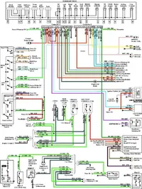
So I did finally get this going. Found a short caused by the fuel level slosh module. Removed the slosh module. Also, found my ignition switch was broken. Replaced that. Finally, found flakey ground readings at pins 40 & 60 at the ECM. Found one of the wires grounded to a screw near the headlight and the other not connected to anything. I ended up connecting them both to the ECM ground at the cylindrical connector at the shock tower. The fuel pump fired right up after this with the key on. I was able to start the car and drive it around for about an hour with no issues. The only question I have now is the ground connection at pin 20 on the ECM. This ground is screwed in to the chassis in the kick panel. Should pin 20 go to the ECM ground at the shock tower as well? It would be connected directly to the battery ground there. Is that recommended?

**UPDATE 2**
Grounding questions solved. Pin 20 is grounded to the chassis at the kick panel. Pins 40 & 60 go to the cylindrical ground connection at the shock tower where it is directly connected to the battery negative terminal.
 
Last edited:
Actually yes it does, do one more test, can you get the ECM to spit out codes?
Honestly, I'd send it off to ECUExchange to get it updated, these things are past there prime. (No pun intended.....maybe).

I’ll whip out the code reader soon and check. One thing that bothers me I just found was the pink/black wire from the fuel pump relay to the fuel pump is shorting to ground. So I disconnected the fuel pump Y harness (plugs into fuel pump and sending unit at the tank) and it’s no longer reading short to ground the pink /black wire. Measuring the yellow wire going through floor of the hatch and its shorting to ground. So it looks like I have an issue in the harness at the tank and the wiring go through the hatch floor that carries power for the fuel pump and sending unit.

1. Does the yellow/white wire go all the way from the trunk to the slosh module at the gauge cluster tank level readout? Is there 12vdc on this yellow wire?

2. The black wire for the sending unit, is that ground?

I’m wondering if this short took out my ECM? The weird thing is the fuel pump was coming on when everything was connected and the test port terminal was jumped under the hood. Before I found the pink/blk wire shirt to ground. Hope I didn’t damage the pump in any way.
 
You need to clear up any shorts to ground and then run your tests again.

If you have power through the inertia switch then the ECU is putting ground to the fuel pump relay like it is supposed to. You will not have voltage at the inertia switch unless the ECU does this.
 
  • Like
Reactions: afjLX
You need to clear up any shorts to ground and then run your tests again.

If you have power through the inertia switch then the ECU is putting ground to the fuel pump relay like it is supposed to. You will not have voltage at the inertia switch unless the ECU does

Thanks for the info. So I pulled the harness on top of the tank and verified all wires are good and nothing shorted against each other inside. Verified there is definitely a short to ground in the yellow power wire that goes into the trunk floor for the fuel sending unit.

Searching the forum, I found a schematic for the sending unit. The yellow wire appears to go into the slosh module at the cluster. My fuel gauge is jacked up and always shows full. So there’s definitely an issue there. I need to pull the cluster and see what’s going on at that slosh module and if it’s shorted there.
 
Its probably the slosh module itself. Pretty sure NPD sells them new if you cannot find a working used one. Found the module on NPD here:

 
Its probably the slosh module itself. Pretty sure NPD sells them new if you cannot find a working used one. Found the module on NPD here:


Thanks!

So I’m just now remembering my 87 was converted to mass air and has the A9L ecm. So will the fuel pump circuit still operate the same way? I know the inertia switch portion is wired differently but as far as from the ecm pin 19 still switches ground on both old and newer fox mustangs.
 
It is PIN 22 that triggers the relay. PIN 19 is conformation that the fuel pump relay is putting out 12V to the fuel pump.

Diagrams courtesy of Tmoss & Stang&2birds
94-95 Mustang wiring diagrams
Mustang FAQ - Wiring & Engine Info

Complete computer, actuator & sensor wiring diagram for 91-93 Mass Air Mustangs
91-93_5.0_EEC_Wiring_Diagram.gif


Complete computer, actuator & sensor wiring diagram for 88-91 Mass Air Mustangs
88-91_5.0_EEC_Wiring_Diagram.gif
 
  • Like
Reactions: Mcmahst
Thanks! I went through the schematics yesterday and traced the wiring to the relay and ECM. It is pin22 on the trigger side of the relay. So the right wire is there. I will probe some more later this week to test the ground switching and verify voltages (again). I also have to pull the cluster to see why the power wire from the slosh module is shorted to ground. I at least have a clear path of things to check. I’m hoping to get some resolution soon. I did pull the A9L ECM and inspected the board. 2 leaking capacitors but no other visible damage or burned traces. I will probably send it to ECU Xchange to have them test and repair it. It’s old and beat up enough to get some new components installed.
 
Well, this is getting really interesting. Traced the short back to the left connector at the instrument cluster. I have the gauge cluster removed, the multifunction switch disconnected, the EEC relay disconnected, the ECM disconnected, the alternator disconnected.

I’m reading a short to ground on connector c250 (left connector) at the gauge cluster on pins 1, 2, 13, & 14. Does anyone have the wiring schematic for the gauge cluster on a 1987 Mustang? I already have the pinout, just looking for the actually wiring diagram.

Any help is greatly appreciated .
 
Does anyone have the wiring schematic for the gauge cluster on a 1987 Mustang? I already have the pinout, just looking for the actually wiring diagram.

Any help is greatly appreciated .

I highly recommend these... have a set myself. They're a nice size, wipe clean, and the wire colors on the diagrams exactly match the wiring on the car. A quality resource.

 
  • Like
Reactions: afjLX

Thanks!!! I already have the Pinout I’m looking for the actual wiring schematic. The one posted above is for a 1990+ car. I need the one for a 1987. I could probably make some common sense calls with wiring from the cluster as usually they’re just moved around on the connector. But I don’t want to go too crazy there.

I did buy a digital download for the 1987 EVTM guide and it’s pretty helpful but no full blown system schematics that are typically at the back of maintenance manuals. Definitely disappointed in that aspect. It does have some schemctics that I will have to jump around in and see if it has the info I need. So far it looks like it may suffice. Looks like I have shorts involved with the lighting as I’m reading shorts at left and right turn signal indicator and the high beam indicator. Will have to continue digging tomorrow (hopefully).
 
Last edited:
Glad you mentioned the EVTM. I have one for an 87 TBird, so that won’t help. So, to help understand, you’re looking for the wiring schematic for the actual instrument cluster, the circuit boards, etc?

Yes sir. Looking for full blown schematics.

As a side note, I figured out I was chasing my tail on some of the shorts as it was the actual light bulb circuit. I did find the ignition switch broken and a bad slush module. So I’m going to replace both and go from there. Also, I am sending my ecm to exuexchange to check and repair/refresh (has leaking caps). Crossing my fingers I’ll be up and running before Turkey day!!