Electrical 91 LX T5 to T56 Swap Check engine light runs terrible

Justin42069

New Member
Apr 4, 2001
15
0
1
Just finished the T5 to T56 swap in my 91 LX. Everything fell right into place no problem. I bought the reverse lock out kit from Nate at wirebarn.com and wired that in no problem. I didn't know what to do with the two plugs under the car that plug into the reverse switch and the neutral safety switch on the T5 so I left them unplugged. Got into the car to start and it wouldn't crank. It acted like the clutch wasn't pushed in all the way. I then cut the male plugs off of my old T5, plugged them into the two connectors that I had left undone, stripped back the wires and twisted them together. My reverse lights started working, so I butt connected that plug together to make it permanent. When I twisted the other plug together, the car cranked and started, so I butt connected those wires together. I assume they went to my neutral safety switch that is on the T5 but not on the T56. My speed sensor is mechanical, so I installed the speedo cable into the speed sensor on the drivers side. I wired the reverse lock out to the electronic speed sensor on the passengers side of the trans. I left the stock speed sensor wiring thats under the bottom of the car that goes to the mechanical speed sensor unplugged. Get in to test drive and the check engine light is on. I use a jumper wire to try and make the check engine light flash on the dash to show codes, but the light just stays on solid. The car runs like hell, spitting and sputtering and it smells like raw fuel is pouring out of the exhaust.

So my questions are: 1 What is the correct wiring for the connectors that are stock to the car but don't have a counter part on the T56? 2 Am I missing some sort of controller or module for the trans? Every article I've read in the month leading up to doing this swap didn't mention any wiring problems. Thanks for the help.
 
  • Sponsors (?)


What codes did you get when you dumped the codes?
Or did you even bother to dump the codes?

Dump codes sticky

Look at the top of the 5.0 Tech forum where the sticky threads are posted. One of them is how to dump the computer codes. Codes may be present even if the CEL (Check Engine Light) isn’t on. You don’t need a code reader or scanner – all you need is a paper clip, or if your lady friend has a hair pin, that will do the job.
I highly suggest that you read it and follow the instructions to dump the codes. http://www.stangnet.com/mustang-forums/threads/how-to-pull-codes-from-eec4.889006/
 
The light didn’t flash when jumped, so no codes found. I tried a scanner today and it said it couldn’t communicate with vehicle. I bought a new pigtail for the VSS and hooked that back up but it didn’t change anything.
 
@Justin42069
Any time the computer will not go into diagnostic mode, you have some serious problems that need to be fixed before you do anything else.


Computer will not go into diagnostic mode on 91-95 model 5.0 Mustangs

Revised Dec 23 2107
1.) To clarify signal ground connections on the engine mounted fuel injector wiring harness and add diagram for the engine mounted fuel injector wiring harness
2.) To add warning about using an automatic transmission O2 sensor wiring harness with a A9L manual shift transmission computer.


How it is supposed to work:
The grey/red wire (pin 46) is signal ground for the computer. It provides a dedicated ground for the EGR, Baro, ACT, ECT, & TPS sensors as well as the ground to put the computer into self-test mode. As long as you are successful dumping the codes by using the gray/red wire on the diagnostic connector for the ground when dumping, the computer’s internal ground on pin 46 is good.

If this ground is bad, none of the sensors mentioned will work properly. That will severely affect the car's performance. You will have hard starting, low power and drivability problems. Since it is a dedicated ground, it passes through the computer on its way to the computer main power ground that terminates at the battery pigtail ground. It should read less than 1 ohm when measured from anyplace on the engine harness with the battery pigtail ground as the other reference point for the ohmmeter probe.

Engine mounted fuel injector wiring harness sensors for a 5.0 mustang
63347.gif


What sometimes happens is that the test connector grey/red wire gets jumpered to power which either burns up the wiring or burns the trace off the pc board inside the computer. That trace connects pins 46 to pins 40 & 60.

OR

If an O2 sensor harness from an automatic transmission Mustang is used with an A9L manual shift transmission computer. The 12 volts from the automatic transmission starter circuit will damage the A9L computer.

The STI (Self Test Input) is jumpered to ground to put the computer into test mode. Jumpering it to power can produce unknown results, including damage to the computer. The ohm test simply verifies that there are no breaks in the wiring between the test connector and the computer input.

How to test the wiring :
With the power off, measure the resistance between the computer test ground (grey/red wire) on the self- test connector and battery ground. You should see less than 1 ohm.

attachment.php


If that check fails, remove the passenger side kick panel and disconnect the computer connector. There is a 10 MM bolt that holds it in place. Measure the resistance between the grey/red wire and pin 46 on the computer wiring connector: it should be less than 1 ohm. More than 1 ohm is a wiring problem. If it reads 1 ohm or less, then the computer is suspect. On the computer, measure the resistance between pin 46 and pins 40 & 60: it should be less than 1 ohm. More than that and the computer’s internal ground has failed, and the computer needs to be repaired or replaced.
While you have the computer connector disconnected from the computer, turn the ignition switch to the Start position and look for 12 volts on pin 46 of the computer wiring harness. If you see 12 volts then you have an automatic transmission O2 sensor harness. That will damage the A9L manual shift transmission computer.


See http://www.stangnet.com/mustang-forums/749974-computer-issue.html#post7490537 for Joel5.0’s fix for the computer internal signal ground.

If the first ground check was good, there are other wires to check. Measure the resistance between the STI computer self-test connector (red/white wire) and pin 48 on the computer main connector: it should be less than 1.5 ohms. More than 1 ohms is a wiring problem

The following is a view from the computer side of the computer wiring connector: it is for an A9L, A9P computer.
eec-iv-computer-connector-for-5-0-mustang-gif.gif


a9x-series-computer-connector-wire-side-view-gif.gif


Diagram courtesy of Tmoss & Stang&2birds

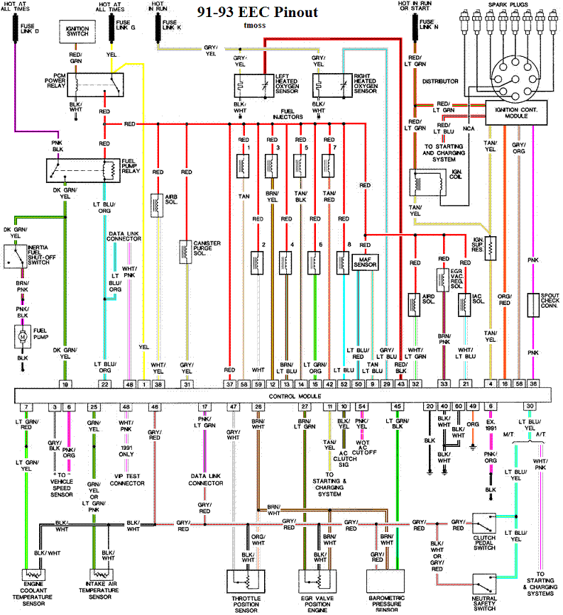
Check out the diagram and notice all the places the grey/red wire goes. Almost every sensor on the engine except the MAF is connected to it.

91-93 5.0 Mustangs
91-93_5.0_EEC_Wiring_Diagram.gif


Complete computer, actuator & sensor wiring diagram for 94-95 Mass Air Mustangs
94-95_5.0_EEC_Wiring_Diagram.gif


See the graphic for the 10 pin connector circuit layout.
salt-pepper-10-pin-connectors-65-jpg.jpg


See the following website for some help from Tmoss (diagram designer) & Stang&2Birds
(website host) for help on 88-95 wiring http://www.veryuseful.com/mustang/tech/engine
 
Wanted to update you on what I found. I started diag at the top of your last reply. I found the ohms on the test wire to batt neg were way too much. I checked continuity on the pins in the ECM and found none. I opened the ECM and found a smoked wire. So now the hunt begins for a new ECM. I will update as I go.
 
Wanted to update you on what I found. I started diag at the top of your last reply. I found the ohms on the test wire to batt neg were way too much. I checked continuity on the pins in the ECM and found none. I opened the ECM and found a smoked wire. So now the hunt begins for a new ECM. I will update as I go.

See http://www.stangnet.com/mustang-forums/749974-computer-issue.html#post7490537 for Joel5.0’s fix for the computer internal signal ground

Look closely at the post - there is a link that tells how to fix the computer PC board. If you don't want to try that, fix a radio/TV repair shop and get them to fix it. It should take less that 15 minutes now that you have to cover off of the computer.
 
I ended up soldering a jumper wire to bypass the burnt part but I also found an A9S on CL and picked it up for $200. The solder job was good enough to fix most of my issues (the MIL is still on but it runs way better and I’m able to pull codes) and drive the car out of the shop but I’m not trusting it as this car is going to be my daily driver in about a week. I’m right in the middle of moving from California to Colorado so when I get out there I will send my comp to a repair shop to have a professional redo my solder job. I got 4 codes 22, 23, 67, and 87. Those will also be dealt with in Colorado. I’m fairly certain that what happened was I took my power probe and started juicing up the wires that plug into the T5 to find the reverse light and sent 12V down the 5V signal wire for the neutral sensing switch and smoked the ECM. Thanks for your help, I wouldn’t have know which wires to test or which pins to check without it.