
So I have an electrical issue, I posted about it awhile back (years) and got a response to change the tfi module, well, I was still in high school and didn't have a job, so the car sat for some time, I started getting some money from work last year and in about October decided to get the car out and start working on it. It refused to start, fixed that issue with a new fuel pump relay. Drove it all October and most of November with no issues. I parked it for winter because it's obviously not for the snow. With the weather finally being warmer, I cleaned it out and got it ready for spring, and started driving it to work this week, but the problem I was experiencing before is back. It seems to only happen in warm weather though, as I can drive to work in the morning fine, as it is chilly, but on the way home the car dies multiple times and I have to limp it home. The issue is that after a little driving the car falls on its face and stalls. The fuel pump relay is chattering as are some relays under the hood. Yesterday I replaced the eec relay and the tfi moudle hoping to fix the issue, but sadly it did not. Hopefully all the experience everyone has here will help me get rid of this issue as it is extremely frustrating. Also, I'm not sure if its worth mentioning, but as the fuel pump relay chatters, the check engine light flashes in tune. Thanks for looking, and thanks for the help.
You are using an out of date browser. It may not display this or other websites correctly.
You should upgrade or use an alternative browser.
You should upgrade or use an alternative browser.
Electrical issue
- Thread starter alexp11
- Start date

Dump the codes: Codes may be present even if the Check Engine Light (CEL) isn't on.
Dumping the computer diagnostic codes on 86-95 Mustangs
Revised 26-July-2011. Added need to make sure the clutch is pressed when dumping codes.
Codes may be present even if the check engine light hasn’t come on, so be sure to check for them.
Here's the way to dump the computer codes with only a jumper wire or paper clip and the check engine light, or test light or voltmeter. I’ve used it for years, and it works great. You watch the flashing test lamp or Check Engine Light and count the flashes.
Post the codes you get and I will post 86-93 model 5.0 Mustang specific code definitions and fixes. I do not have a complete listing for 94-95 model 5.0 Mustangs at this time.
Be sure to turn off the A/C, and put the transmission in neutral when dumping the codes. On a manual transmission car, be sure to press the clutch to the floor.
Fail to do this and you will generate a code 67 and not be able to dump the Engine Running codes.
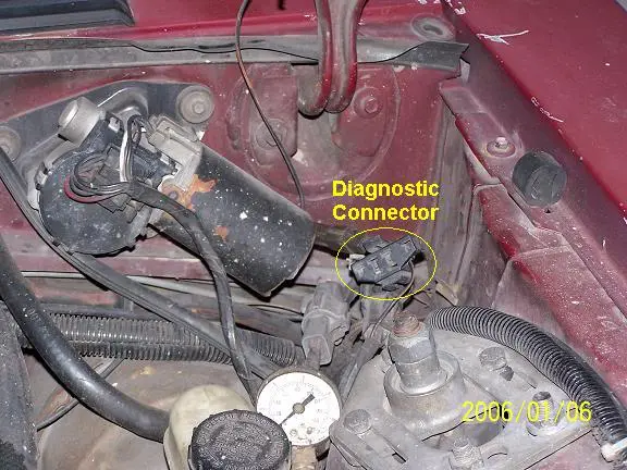
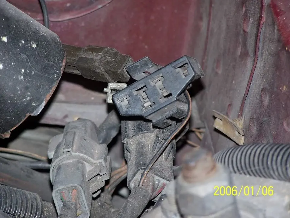
If your car is an 86-88 stang, you'll have to use the test lamp or voltmeter method. There is no functional check engine light on the 86-88's except possibly the Cali Mass Air cars.

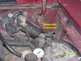
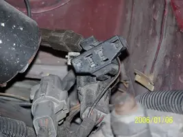
The STI has a gray connector shell and a white/red wire. It comes from the same bundle of wires as the self test connector.
89 through 95 cars have a working Check Engine light. Watch it instead of using a test lamp.

The STI has a gray connector shell and a white/red wire. It comes from the same bundle of wires as the self test connector.
WARNING!!! There is a single dark brown connector with a black/orange wire. It is the 12 volt power to the under the hood light. Do not jumper it to the computer test connector. If you do, you will damage the computer.
What to expect:
You should get a code 11 (two single flashes in succession). This says that the computer's internal workings are OK, and that the wiring to put the computer into diagnostic mode is good. No code 11 and you have some wiring problems. This is crucial: the same wire that provides the ground to dump the codes provides signal ground for the TPS, EGR, ACT and Map/Baro sensors. If it fails, you will have poor performance, economy and driveablity problems
Some codes have different answers if the engine is running from the answers that it has when the engine isn't running. It helps a lot to know if you had the engine running when you ran the test.
Dumping the Engine Running codes: The procedure is the same, you start the engine with the test jumper in place. Be sure the A/C is off, and clutch (if present) is pressed to the floor, and the transmission is in neutral. You'll get an 11, then a 4 and the engine will speed up to do the EGR test. After the engine speed decreases back to idle, it will dump the engine running codes.
Trouble codes are either 2 digit or 3 digit, there are no cars that use both 2 digit codes and 3 digit codes.
Your 86-88 5.0 won't have a working Check Engine Light, so you'll need a test light.
See AutoZone Part Number: 25886 , $10

Alternate methods:
For those who are intimidated by all the wires & connections, see Actron® for what a typical hand scanner looks like. Normal retail price is about $30 or so at AutoZone or Wal-Mart.
Or for a nicer scanner see Equus - Digital Ford Code Reader (3145) – It has a 3 digit LCD display so that you don’t have to count flashes or beeps.. Cost is $30-$36.
Dumping the computer diagnostic codes on 86-95 Mustangs
Revised 26-July-2011. Added need to make sure the clutch is pressed when dumping codes.
Codes may be present even if the check engine light hasn’t come on, so be sure to check for them.
Here's the way to dump the computer codes with only a jumper wire or paper clip and the check engine light, or test light or voltmeter. I’ve used it for years, and it works great. You watch the flashing test lamp or Check Engine Light and count the flashes.
Post the codes you get and I will post 86-93 model 5.0 Mustang specific code definitions and fixes. I do not have a complete listing for 94-95 model 5.0 Mustangs at this time.
Be sure to turn off the A/C, and put the transmission in neutral when dumping the codes. On a manual transmission car, be sure to press the clutch to the floor.
Fail to do this and you will generate a code 67 and not be able to dump the Engine Running codes.
If your car is an 86-88 stang, you'll have to use the test lamp or voltmeter method. There is no functional check engine light on the 86-88's except possibly the Cali Mass Air cars.
The STI has a gray connector shell and a white/red wire. It comes from the same bundle of wires as the self test connector.
89 through 95 cars have a working Check Engine light. Watch it instead of using a test lamp.
The STI has a gray connector shell and a white/red wire. It comes from the same bundle of wires as the self test connector.
WARNING!!! There is a single dark brown connector with a black/orange wire. It is the 12 volt power to the under the hood light. Do not jumper it to the computer test connector. If you do, you will damage the computer.
What to expect:
You should get a code 11 (two single flashes in succession). This says that the computer's internal workings are OK, and that the wiring to put the computer into diagnostic mode is good. No code 11 and you have some wiring problems. This is crucial: the same wire that provides the ground to dump the codes provides signal ground for the TPS, EGR, ACT and Map/Baro sensors. If it fails, you will have poor performance, economy and driveablity problems
Some codes have different answers if the engine is running from the answers that it has when the engine isn't running. It helps a lot to know if you had the engine running when you ran the test.
Dumping the Engine Running codes: The procedure is the same, you start the engine with the test jumper in place. Be sure the A/C is off, and clutch (if present) is pressed to the floor, and the transmission is in neutral. You'll get an 11, then a 4 and the engine will speed up to do the EGR test. After the engine speed decreases back to idle, it will dump the engine running codes.
Trouble codes are either 2 digit or 3 digit, there are no cars that use both 2 digit codes and 3 digit codes.
Your 86-88 5.0 won't have a working Check Engine Light, so you'll need a test light.
See AutoZone Part Number: 25886 , $10
Alternate methods:
For those who are intimidated by all the wires & connections, see Actron® for what a typical hand scanner looks like. Normal retail price is about $30 or so at AutoZone or Wal-Mart.
Or for a nicer scanner see Equus - Digital Ford Code Reader (3145) – It has a 3 digit LCD display so that you don’t have to count flashes or beeps.. Cost is $30-$36.
Attachments
The code 67 is the reason for not being able to dump the engine runnung codes. You MUST press the clutch to the floor and hold it there when dumping the codes.Can't get it to pull engine running codes. But car is a 90 gt hatch if it makes any differences. I'm off for the night, Thanks for the help, and sorry for the double posts.
Code 67 –
Revised 2 Nov 2012 to add definition of the NSS functions for both 5 speed and auto transmissions
Cause of problem:
clutch not depressed (5 speed) or car not in neutral or park (auto) or A/C in On position when codes where dumped. Possible neutral safety switch or wiring problem. This code may prevent you from running the Key On Engine On tests. External evidence from other sources claims that a code 67 can cause an idle surge condition. Do try to find and fix any issues with the switch and wiring if you get a code 67.
What the NSS (Neutral Safety Switch) does:
5 speed transmission: It has no connection with the starter, and the engine can be cranked without it being connected.
Auto transmission: It is the safety interlock that prevents the starter from cranking the engine with the transmission in gear.
What it does for both 5 speed and auto transmission cars:
The computer wants to make sure the A/C is off due to the added load on the engine for the engine running computer diagnostic tests. It also checks to see that the transmission is in Neutral (5 speed and auto transmission) and the clutch depressed (T5, T56, Tremec 3550 & TKO)). This prevents the diagnostics from being run when the car is driven. Key On Engine Running test mode takes the throttle control away from the driver for several tests. This could prove hazardous if the computer was jumpered into test mode and then driven.
The following is for 5 speed cars only.
The NSS code 67 can be bypassed for testing. You will need to temporarily ground computer pin 30 to the chassis. Computer pin 30 uses a Lt blue/yellow wire. Remove the passenger side kick panel and then remove the plastic cover from the computer wiring connector. Use a safety pin to probe the connector from the rear. Jumper the safety pin to the ground near the computer.
Be sure to remove the jumper BEFORE attempting to drive the car!!!
Code 81 – Secondary Air Injection Diverter Solenoid failure AM2. The solenoid valve located on the back side of the passenger side wheel well is not functional. Possible bad wiring, bad connections, missing or defective solenoid valve. Check the solenoid valve for +12 volts at the Red wire and look for the Lt Green/Black wire to switch from +12 volts to 1 volt or less. The computer controls the valve by providing a ground path on the LT Green/Black wire for the solenoid valve.
With the with the ignition on, look for 12 volts on the red wire on the solenoid connector. No 12 volts and you have wiring problems.
With the engine running, stick a safety pin in the LT Green/Black wire for the solenoid valve & ground it. That should turn the solenoid on and cause air to flow out the port that goes to the pipe connected to the cats. If it doesn't, the valve is bad. If it does cause the airflow to switch, the computer or wiring going to the computer is not signaling the solenoid valve to open.
Putting the computer into self test mode will cause the solenoid valve to toggle. If you listen carefully, you may hear it change states.
Code 82 – Secondary Air Injection Diverter Solenoid failure AM1. Possible bad wiring, bad connections, missing or defective solenoid valve. Check the solenoid valve for +12 volts at the Red wire and look for the Red/White wire to switch from +12 volts to 1 volt or less. The computer controls the valve by providing a ground path on the Red/White wire for the solenoid valve
With the engine running, stick a safety pin in the Red/White wire for the solenoid valve & ground it. That should turn the solenoid on and cause air to flow out the port that goes to the pipe connected to the heads. If it doesn't, the valve is bad. If it does cause the airflow to switch, the computer or wiring going to the computer is not signaling the solenoid valve to open.
Both 81 & 82 codes usually mean that some uneducated person removed the solenoid control valves for the Thermactor Air system in an attempt to make the car faster. It doesn't work that way: no working control valves can cause the cat converters to choke and clog. If you do not have cat converters on the car, you can ignore the 81 & 82 codes.
Code 85 - CANP solenoid - The Carbon Canister solenoid is inoperative or missing. Check vacuum lines for leaks and cracks. Check electrical wiring for loose connections, damaged wiring and insulation. Check solenoid valve operation by grounding the gray/yellow wire to the solenoid and blowing through it.
The computer provides the ground for the solenoid. The red wire to the solenoid is always energized any time the ignition switch is in the run position.
Charcoal canister plumbing - one 3/8" tube from the bottom of the upper manifold to the rubber hose. Rubber hose connects to one side of the canister solenoid valve. Other side of the solenoid valve connects to one side of the canister. The other side of the canister connects to a rubber hose that connects to a line that goes all the way back to the gas tank. There is an electrical connector coming from the passenger side injector harness near #1 injector that plugs into the canister solenoid valve. It's purpose is to vent the gas tank. The solenoid valve opens at cruse to provide some extra fuel. The canister is normally mounted on the passenger side frame rail near the smog pump pulley.
It does not weigh but a pound or so and helps richen up the cruse mixture. It draws no HP & keeps the car from smelling like gasoline in a closed garage. So with all these good things and no bad ones, why not hook it up & use it?
The purge valve solenoid connector is a dangling wire that is near the ECT sensor and oil filler on the passenger side rocker cover. The actual solenoid valve is down next to the carbon canister. There is about 12"-16" of wire that runs parallel to the canister vent hose that comes off the bottom side of the upper intake manifold. That hose connects one port of the solenoid valve; the other port connects to the carbon canister.
The purge valve solenoid should be available at your local auto parts store.
Purge valve solenoid:

The carbon canister is normally mounted on the passenger side frame rail near the smog pump pulley.
Carbon Canister:

Code 15 - No Keep Alive Memory power to PCM pin 1 or bad PCM (Memory Test
Failure). The voltage to the Keep Alive Memory (KAM) is missing (wiring problem)
or the KAM is bad. The KAM holds all of the settings that the computer "learns" as
it operates and all the stored error codes that are generated as a result of
something malfunctioning while the engine is running. Use a voltmeter to check
the voltage to the pin 1 on the computer - you should always have 12 volts. No
constant 12 volts = bad wiring. If you do always have the 12 volts, then the KAM is
bad and the computer is faulty.
If the computer has to "relearn" all the optimum settings every time it powers up,
the initial 5-30 minutes of operation may exhibit surges, poor low speed performance,
and rough idle.
Note that some aftermarket chips will cause code 15 to set. Remove the chip,
clear the codes and retest.
Before replacing the computer, remove the battery ground cable for about 20
minutes. This will clear all the codes. Retest after several days of running. If the 15
code is gone, then don't worry about it. If it is still there, then you get to do some
troubleshooting.
See the following website for some help from Tmoss (diagram designer) & Stang&2
Birds (website host) for help on 88-95 wiring http://www.veryuseful.com/mustang/tech/engine/
Diagram courtesy of Tmoss & Stang&2birds
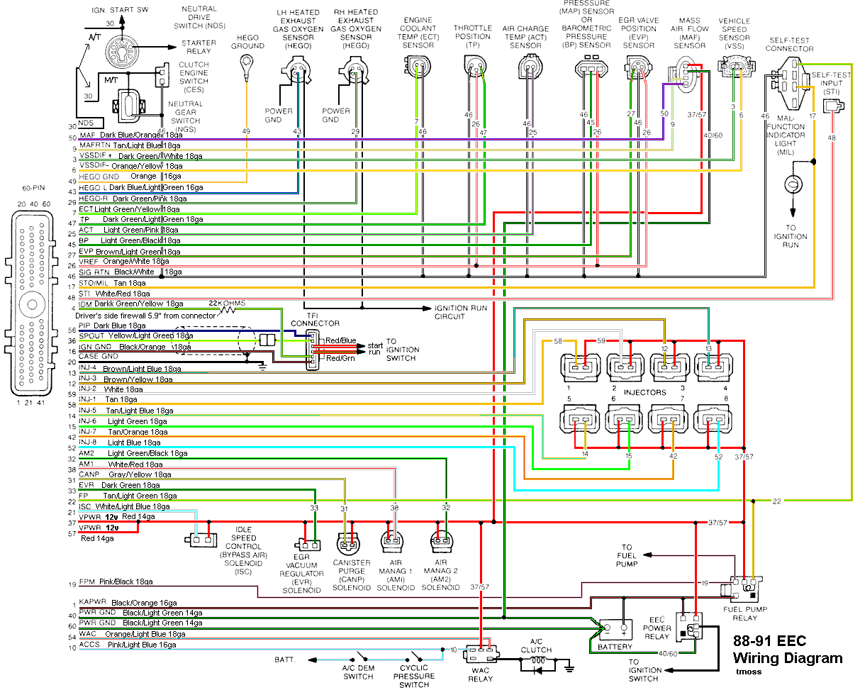
http://www.veryuseful.com/mustang/tech/engine/images/IgnitionSwitchWiring.gif
http://www.veryuseful.com/mustang/tech/engine/images/fuel-alt-links-ign-ac.gif
http://www.veryuseful.com/mustang/tech/engine/images/88-91_5.0_EEC_Wiring_Diagram.gif
Thermactor Air System
Some review of how it works...
Revised 17-Sept-2011 to add testing procedure.
The Thermactor air pump (smog pump) supplies air to the heads or catalytic converters. This air helps break down the excess HC (hydrocarbons) and CO (carbon monoxide). The air supplied to the catalytic converters helps create the catalytic reaction that changes the HC & CO into CO2 and water vapor. Catalytic converters on 5.0 Mustangs are designed to use the extra air provided by the smog pump. Without the extra air, the catalytic converters will clog and fail.
The Thermactor air pump draws air from an inlet filter in the front of the pump. The smog pump puts air into the heads when the engine is cold and then into the catalytic converters when it is warm. The Thermactor control valves serve to direct the flow. The first valve, TAB (Thermactor Air Bypass) or AM1 valve) either dumps air to the atmosphere or passes it on to the second valve. The second valve, TAD (Thermactor Air Diverter valve or AM2 valve) directs it to the heads or the catalytic converters. Check valves located after the TAB & TAD solenoids prevent hot exhaust gases from damaging the control valves or pump in case of a backfire. The air serves to help consume any unburned hydrocarbons by supplying extra oxygen to the catalytic process. The computer tells the Thermactor Air System to open the Bypass valve at WOT (wide open throttle) minimizing engine drag. This dumps the pump's output to the atmosphere, and reduces the parasitic drag caused by the smog pump to about 2-4 HP at WOT. The Bypass valve also opens during deceleration to reduce or prevent backfires.
Code 44 RH side air not functioning.
Code 94 LH side air not functioning.
The computer uses the change in the O2 sensor readings to detect operation of the Thermactor control valves. When the dump valve opens, it reduces the O2 readings in the exhaust system. Then it closes the dump valve and the O2 readings increase. By toggling the dump valve (TAB), the computer tests for the 44/94 codes.
Failure mode is usually due to a clogged air crossover tube, where one or both sides of the tube clog with carbon. The air crossover tube mounts on the back of the cylinder heads and supplies air to each of the Thermactor air passages cast into the cylinder heads. When the heads do not get the proper air delivery, they set codes 44 & 94, depending on which passage is clogged. It is possible to get both 44 & 94, which would suggest that the air pump or control valves are not working correctly, or the crossover tube is full of carbon or missing.
Computer operation & control for the Thermactor Air System
Automobile computers use current sink technology. They do not source power to any relay, solenoid or actuator like the IAC, fuel pump relay, or fuel injectors. Instead the computer provides a ground path for the positive battery voltage to get back to the battery negative terminal. That flow of power from positive to negative is what provides the energy to make the IAC, fuel pump relay, or fuel injectors work. No ground provided by the computer, then the actuators and relays don't operate.
One side of the any relay/actuator/solenoid in the engine compartment will be connected to a red wire that has 12-14 volts anytime the ignition switch is in the run position. The other side will have 12-14 volts when the relay/actuator/solenoid isn't turned on. Once the computer turns on the clamp side, the voltage on the computer side of the wire will drop down to 1 volt or less.
In order to test the TAD/TAB solenoids, you need to ground the white/red wire on the TAB solenoid or the light green/black wire on the TAD solenoid.
For 94-95 cars: the colors are different. The White/Red wire (TAB control) is White/Orange (Pin 31 on the PCM). The Green/Black wire (TAD control) should be Brown (pin 34 at the PCM). Thanks to HISSIN50 for this tip.
Testing the system:
To test the computer, you can use a test light across the TAB or TAD wiring connectors and dump the codes. When you dump the codes, the computer does a self test that toggles every relay/actuator/solenoid on and off. When this happens, the test light will flicker.
Disconnect the big hose from smog pump: with the engine running you should feel air output. Reconnect the smog pump hose & apply vacuum to the first vacuum controlled valve: Its purpose is to either dump the pump's output to the atmosphere or pass it to the next valve.
The next vacuum controlled valve directs the air to either the cylinder heads when the engine is cold or to the catalytic converter when the engine is warm. Disconnect the big hoses from the back side of the vacuum controlled valve and start the engine. Apply vacuum to the valve and see if the airflow changes from one hose to the next.
The two electrical controlled vacuum valves mounted on the rear of the passenger side wheel well turn the vacuum on & off under computer control. Check to see that both valves have +12 volts on the red wire. Then ground the white/red wire and the first solenoid should open and pass vacuum. Do the same thing to the light green/black wire on the second solenoid and it should open and pass vacuum.
Remember that the computer does not source power for any actuator or relay, but provides the ground necessary to complete the circuit. That means one side of the circuit will always be hot, and the other side will go to ground or below 1 volt as the computer switches on that circuit.
The computer provides the ground to complete the circuit to power the solenoid valve that turns the
vacuum on or off. The computer is located under the passenger side kick panel. Remove the kick panel & the cover over the computer wiring connector pins. Check Pin 38 Solenoid valve #1 that provides vacuum to the first Thermactor control valve for a switch from 12-14 volts to 1 volt or less. Do the same with pin 32 solenoid valve #2 that provides vacuum to the second Thermactor control valve. Starting the engine with the computer jumpered to self test mode will cause all the actuators to toggle on and off. If after doing this and you see no switching of the voltage on and off, you can start testing the wiring for shorts to ground and broken wiring. An Ohm check to ground with the computer connector disconnected & the solenoid valves disconnected should show open circuit between the pin 32 and ground and again on pin 38 and ground. In like manner, there should be less than 1 ohm between pin 32 and solenoid valve #2 and pin 38 & Solenoid valve #1.
If after checking the resistance of the wiring & you are sure that there are no wiring faults, start looking at the solenoid valves. If you disconnect them, you can jumper power & ground to them to verify operation. Power & ground supplied should turn on the vacuum flow, remove either one and the vacuum should stop flowing.
Typical resistance of the solenoid valves is in the range of 20-70 Ohms.
Theory of operation:
Catalytic converters consist of two different types of catalysts: Reduction and Oxidation.
The Reduction catalyst is the first converter in a 5.0 Mustang, and the Oxidation converter is the second converter. The Oxidation converter uses the extra air from the smog pump to burn the excess HC. Aftermarket converters that use the smog pump often combine both types of catalysts in one housing. Since all catalytic reactions depend on heat to happen, catalytic converters do not work as efficiently with long tube headers. The extra length of the long tubes reduces the heat available to operate the O2 sensors and the catalytic converters. That will cause emissions problems, and reduce the chances of passing an actual smog test.
Now for the Chemistry...
"The reduction catalyst is the first stage of the catalytic converter. It uses platinum and rhodium to help reduce the NOx emissions. When an NO or NO2 molecule contacts the catalyst, the catalyst rips the nitrogen atom out of the molecule and holds on to it, freeing the oxygen in the form of O2. The nitrogen atoms bond with other nitrogen atoms that are also stuck to the catalyst, forming N2. For example:
2NO => N2 + O2 or 2NO2 => N2 + 2O2
The oxidation catalyst is the second stage of the catalytic converter. It reduces the unburned hydrocarbons and carbon monoxide by burning (oxidizing) them over a platinum and palladium catalyst. This catalyst aids the reaction of the CO and hydrocarbons with the remaining oxygen in the exhaust gas. For example:
2CO + O2 => 2CO2
There are two main types of structures used in catalytic converters -- honeycomb and ceramic beads. Most cars today use a honeycomb structure." Quote courtesy of How Stuff Works (HowStuffWorks "Catalysts")
What happens when there is no extra air from the smog pump...
As engines age, the quality of tune decreases and wear causes them to burn oil. We have all seem cars that go down the road puffing blue or black smoke from the tailpipe. Oil consumption and poor tune increase the amount of HC the oxidation catalyst has to deal with. The excess HC that the converters cannot oxidize due to lack of extra air becomes a crusty coating inside the honeycomb structure. This effectively reduces the size of the honeycomb passageways and builds up thicker over time and mileage. Continuous usage under such conditions will cause the converter to fail and clog. The extra air provided by the Thermactor Air System (smog pump) is essential for the oxidation process. It oxidizes the added HC from oil consumption and poor tune and keeps the HC levels within acceptable limits.
Newer catalytic converters do not use the Thermactor Air System (smog pump) because they are designed to work with an improved computer system that runs leaner and cleaner
They add an extra set of O2 sensors after the catalytic converters to monitor the oxygen and HC levels. Using this additional information, the improved computer system adjusts the air/fuel mixture for cleaner combustion and reduced emissions. If the computer cannot compensate for the added load of emissions due to wear and poor tune, the catalytic converters will eventually fail and clog. The periodic checks (smog inspections) are supposed to help owners keep track of problems and get them repaired. Use them on an 86-95 Mustang and you will slowly kill them with the pollutants that they are not designed to deal with.
Not sure when I'll have the free time to do some more work, but I read through most of what you put, and I do know that the carbon can has been removed from the car as well as the smog pump. I do have a catless h-pipe I will get on asap, but for the carbon can, is there a way to "bypass" the wiring for it, or should I try to pick a replacement up and get it working like factory? Thanks a ton for all the help!
- Alex
- Alex
Just got back to doing some work although not specifically related to the problem, clutch issues. After oriley's giving me the wrong one, I'm gonna get one from summit, heading up tomorrow, Gonna swap out the h pipe as well hopefully. One of the bolts from the h pipe to the headers stripped. Still a factory h pipe with 4 cats. lol While under there however, I did notice the hole for the o2 sensor on the passenger side was plugged with a bolt, I didn't see any wiring in the area that looked like it would connect to a sensor, do you think this could possibly be part of the issue, or maybe a reason the car runs a little odd?
Just got back to doing some work although not specifically related to the problem, clutch issues. After oriley's giving me the wrong one, I'm gonna get one from summit, heading up tomorrow, Gonna swap out the h pipe as well hopefully. One of the bolts from the h pipe to the headers stripped. Still a factory h pipe with 4 cats. lol While under there however, I did notice the hole for the o2 sensor on the passenger side was plugged with a bolt, I didn't see any wiring in the area that looked like it would connect to a sensor, do you think this could possibly be part of the issue, or maybe a reason the car runs a little odd?
That should have tripped a 41 O2 sensor code if the computer is working properly. It would cause the engine to be rough running.
Here's the test path for O2 sensors: use it to check the O2 sensors and wiring.
Code 41 or 91 Three digit code 172 or 176 - O2 sensor indicates system lean. Look for a vacuum leak or failing O2 sensor.
Revised 06-Sep-2012 remove smog pump crossover tube reference
Code 41 is a RH side sensor,
Code 91 is the LH side sensor.
Code 172 is the RH side sensor
Code 176 is the LH side sensor
The computer sees a lean mixture signal coming from the O2 sensors and tries to compensate by adding more fuel. Many times the end result is an engine that runs pig rich and stinks of unburned fuel.
The following is a Quote from Charles O. Probst, Ford fuel Injection & Electronic Engine control:
"When the mixture is lean, the exhaust gas has oxygen, about the same amount as the ambient air. So the sensor will generate less than 400 Millivolts. Remember lean = less voltage.
When the mixture is rich, there's less oxygen in the exhaust than in the ambient air , so voltage is generated between the two sides of the tip. The voltage is greater than 600 millivolts. Remember rich = more voltage.
Here's a tip: the newer the sensor, the more the voltage changes, swinging from as low as 0.1 volt to as much as 0.9 volt. As an oxygen sensor ages, the voltage changes get smaller and slower - the voltage change lags behind the change in exhaust gas oxygen.
Because the oxygen sensor generates its own voltage, never apply voltage and never measure resistance of the sensor circuit. To measure voltage signals, use an analog voltmeter with a high input impedance, at least 10 megohms. Remember, a digital voltmeter will average a changing voltage." End Quote
Testing the O2 sensors 87-93 5.0 Mustangs
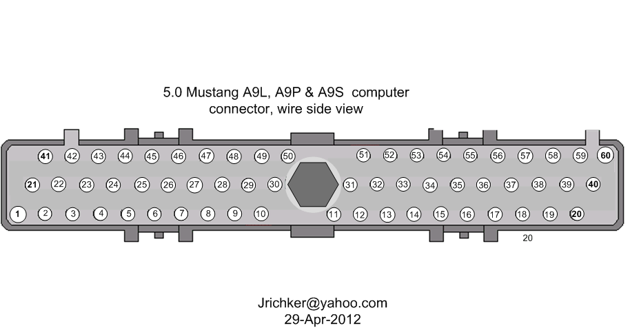
Measuring the O2 sensor voltage at the computer will give you a good idea of how well they are working. You'll have to pull the passenger side kick panel off to gain access to the computer connector. Remove the plastic wiring cover to get to the back side of the wiring. Use a safety pin or paper clip to probe the connections from the rear.
Disconnect the O2 sensor from the harness and use the body side O2 sensor harness as the starting point for testing. Do not measure the resistance of the O2 sensor , you may damage it. Resistance measurements for the O2 sensor harness are made with one meter lead on the O2 sensor harness and the other meter lead on the computer wire or pin for the O2 sensor.
Backside view of the computer wiring connector:
87-90 5.0 Mustangs:
Computer pin 43 Dark blue/Lt green – LH O2 sensor
Computer pin 29 Dark Green/Pink – RH O2 sensor
The computer pins are 29 (LH O2 with a dark green/pink wire) and 43 (RH O2 with a dark blue/pink wire). Use the ground next to the computer to ground the voltmeter. The O2 sensor voltage should switch between .2-.9 volt at idle.
91-93 5.0 Mustangs:
Computer pin 43 Red/Black – LH O2 sensor
Computer pin 29 Gray/Lt blue – RH O2 sensor
The computer pins are 29 (LH O2 with a Gray/Lt blue wire) and 43 (RH O2 with a Red/Black wire). Use the ground next to the computer to ground the voltmeter. The O2 sensor voltage should switch between .2-.9 volt at idle.
Testing the O2 sensors 94-95 5.0 Mustangs
Measuring the O2 sensor voltage at the computer will give you a good idea of how well they are working. You'll have to pull the passenger side kick panel off to gain access to the computer connector. Remove the plastic wiring cover to get to the back side of the wiring. Use a safety pin or paper clip to probe the connections from the rear. The computer pins are 29 (LH O2 with a red/black wire) and 27 (RH O2 with a gray/lt blue wire). Use pin 32 (gray/red wire) to ground the voltmeter. The O2 sensor voltage should switch between .2-.9 volt at idle.
Note that all resistance tests must be done with power off. Measuring resistance with a circuit powered on will give false readings and possibly damage the meter. Do not attempt to measure the resistance of the O2 sensors, it may damage them.
Testing the O2 sensor wiring harness
Most of the common multimeters have a resistance scale. Be sure the O2 sensors are disconnected and measure the resistance from the O2 sensor body harness to the pins on the computer. Using the Low Ohms range (usually 200 Ohms) you should see less than 1.5 Ohms.
87-90 5.0 Mustangs:
Computer pin 43 Dark blue/Lt green – LH O2 sensor
Computer pin 29 Dark Green/Pink – RH O2 sensor
Disconnect the connector from the O2 sensor and measure the resistance:
From the Dark blue/Lt green wire in the LH O2 sensor harness and the Dark blue/Lt green wire on the computer pin 43
From the Dark Green/Pink wire on the RH Os sensor harness and the Dark Green/Pink wire on the computer pin 43
91-93 5.0 Mustangs:
Computer pin 43 Red/Black – LH O2 sensor
Computer pin 29 Gray/Lt blue – RH O2 sensor
Disconnect the connector from the O2 sensor and measure the resistance:
From the Red/Black wire in the LH O2 sensor harness and the Red/Black wire on the computer pin 43
From the Dark Green/Pink Gray/Lt blue wire on the RH Os sensor harness and the Gray/Lt blue wire on the computer pin 29
94-95 5.0 Mustangs:
Computer pin 29 Red/Black – LH O2 sensor
Computer pin 27 Gray/Lt blue – RH O2 sensor
From the Red/Black wire in the LH O2 sensor harness and the Red/Black wire on the computer pin 29
From the Dark Green/Pink Gray/Lt blue wire on the RH Os sensor harness and the Gray/Lt blue wire on the computer pin 27
There is a connector between the body harness and the O2 sensor harness. Make sure the connectors are mated together, the contacts and wiring are not damaged and the contacts are clean and not coated with oil.
The O2 sensor ground (orange wire with a ring terminal on it) is in the wiring harness for the fuel injection wiring. I grounded mine to one of the intake manifold bolts
Make sure you have the proper 3 wire O2 sensors. Only the 4 cylinder cars used a 4 wire sensor, which is not compatible with the V8 wiring harness.
Replace the O2 sensors in pairs if replacement is indicated. If one is weak or bad, the other one probably isn't far behind.
If you get only code 41 and have changed the sensor, look for vacuum leaks. This is especially true if you are having idle problems. The small plastic tubing is very brittle after many years of the heating it receives. Replace the tubing and check the PVC and the hoses connected to it.
Code 41 or 91 Three digit code 172 or 176 - O2 sensor indicates system lean. Look for a vacuum leak or failing O2 sensor.
Revised 06-Sep-2012 remove smog pump crossover tube reference
Code 41 is a RH side sensor,
Code 91 is the LH side sensor.
Code 172 is the RH side sensor
Code 176 is the LH side sensor
The computer sees a lean mixture signal coming from the O2 sensors and tries to compensate by adding more fuel. Many times the end result is an engine that runs pig rich and stinks of unburned fuel.
The following is a Quote from Charles O. Probst, Ford fuel Injection & Electronic Engine control:
"When the mixture is lean, the exhaust gas has oxygen, about the same amount as the ambient air. So the sensor will generate less than 400 Millivolts. Remember lean = less voltage.
When the mixture is rich, there's less oxygen in the exhaust than in the ambient air , so voltage is generated between the two sides of the tip. The voltage is greater than 600 millivolts. Remember rich = more voltage.
Here's a tip: the newer the sensor, the more the voltage changes, swinging from as low as 0.1 volt to as much as 0.9 volt. As an oxygen sensor ages, the voltage changes get smaller and slower - the voltage change lags behind the change in exhaust gas oxygen.
Because the oxygen sensor generates its own voltage, never apply voltage and never measure resistance of the sensor circuit. To measure voltage signals, use an analog voltmeter with a high input impedance, at least 10 megohms. Remember, a digital voltmeter will average a changing voltage." End Quote
Testing the O2 sensors 87-93 5.0 Mustangs
Measuring the O2 sensor voltage at the computer will give you a good idea of how well they are working. You'll have to pull the passenger side kick panel off to gain access to the computer connector. Remove the plastic wiring cover to get to the back side of the wiring. Use a safety pin or paper clip to probe the connections from the rear.
Disconnect the O2 sensor from the harness and use the body side O2 sensor harness as the starting point for testing. Do not measure the resistance of the O2 sensor , you may damage it. Resistance measurements for the O2 sensor harness are made with one meter lead on the O2 sensor harness and the other meter lead on the computer wire or pin for the O2 sensor.
Backside view of the computer wiring connector:
87-90 5.0 Mustangs:
Computer pin 43 Dark blue/Lt green – LH O2 sensor
Computer pin 29 Dark Green/Pink – RH O2 sensor
The computer pins are 29 (LH O2 with a dark green/pink wire) and 43 (RH O2 with a dark blue/pink wire). Use the ground next to the computer to ground the voltmeter. The O2 sensor voltage should switch between .2-.9 volt at idle.
91-93 5.0 Mustangs:
Computer pin 43 Red/Black – LH O2 sensor
Computer pin 29 Gray/Lt blue – RH O2 sensor
The computer pins are 29 (LH O2 with a Gray/Lt blue wire) and 43 (RH O2 with a Red/Black wire). Use the ground next to the computer to ground the voltmeter. The O2 sensor voltage should switch between .2-.9 volt at idle.
Testing the O2 sensors 94-95 5.0 Mustangs
Measuring the O2 sensor voltage at the computer will give you a good idea of how well they are working. You'll have to pull the passenger side kick panel off to gain access to the computer connector. Remove the plastic wiring cover to get to the back side of the wiring. Use a safety pin or paper clip to probe the connections from the rear. The computer pins are 29 (LH O2 with a red/black wire) and 27 (RH O2 with a gray/lt blue wire). Use pin 32 (gray/red wire) to ground the voltmeter. The O2 sensor voltage should switch between .2-.9 volt at idle.
Note that all resistance tests must be done with power off. Measuring resistance with a circuit powered on will give false readings and possibly damage the meter. Do not attempt to measure the resistance of the O2 sensors, it may damage them.
Testing the O2 sensor wiring harness
Most of the common multimeters have a resistance scale. Be sure the O2 sensors are disconnected and measure the resistance from the O2 sensor body harness to the pins on the computer. Using the Low Ohms range (usually 200 Ohms) you should see less than 1.5 Ohms.
87-90 5.0 Mustangs:
Computer pin 43 Dark blue/Lt green – LH O2 sensor
Computer pin 29 Dark Green/Pink – RH O2 sensor
Disconnect the connector from the O2 sensor and measure the resistance:
From the Dark blue/Lt green wire in the LH O2 sensor harness and the Dark blue/Lt green wire on the computer pin 43
From the Dark Green/Pink wire on the RH Os sensor harness and the Dark Green/Pink wire on the computer pin 43
91-93 5.0 Mustangs:
Computer pin 43 Red/Black – LH O2 sensor
Computer pin 29 Gray/Lt blue – RH O2 sensor
Disconnect the connector from the O2 sensor and measure the resistance:
From the Red/Black wire in the LH O2 sensor harness and the Red/Black wire on the computer pin 43
From the Dark Green/Pink Gray/Lt blue wire on the RH Os sensor harness and the Gray/Lt blue wire on the computer pin 29
94-95 5.0 Mustangs:
Computer pin 29 Red/Black – LH O2 sensor
Computer pin 27 Gray/Lt blue – RH O2 sensor
From the Red/Black wire in the LH O2 sensor harness and the Red/Black wire on the computer pin 29
From the Dark Green/Pink Gray/Lt blue wire on the RH Os sensor harness and the Gray/Lt blue wire on the computer pin 27
There is a connector between the body harness and the O2 sensor harness. Make sure the connectors are mated together, the contacts and wiring are not damaged and the contacts are clean and not coated with oil.
The O2 sensor ground (orange wire with a ring terminal on it) is in the wiring harness for the fuel injection wiring. I grounded mine to one of the intake manifold bolts
Make sure you have the proper 3 wire O2 sensors. Only the 4 cylinder cars used a 4 wire sensor, which is not compatible with the V8 wiring harness.
Replace the O2 sensors in pairs if replacement is indicated. If one is weak or bad, the other one probably isn't far behind.
If you get only code 41 and have changed the sensor, look for vacuum leaks. This is especially true if you are having idle problems. The small plastic tubing is very brittle after many years of the heating it receives. Replace the tubing and check the PVC and the hoses connected to it.

Dkeister
New Member
Along with what everyone else has said I had very similar problems and I think you should check the capacitors in your ecm they become corroided many times and can cause all sorts of issues. Take the lid off your ecm and with a flashlight look very closely at the two wires connecting them to the circuit board most likely them will be messed up and you can get replacemnets at radio shack this fixed my 91 perfectly! Hope it helps
Similar threads

- Replies
- 16
- Views
- 364

- Replies
- 6
- Views
- 118

- Replies
- 25
- Views
- 798

- Replies
- 3
- Views
- 252

- Replies
- 8
- Views
- 282