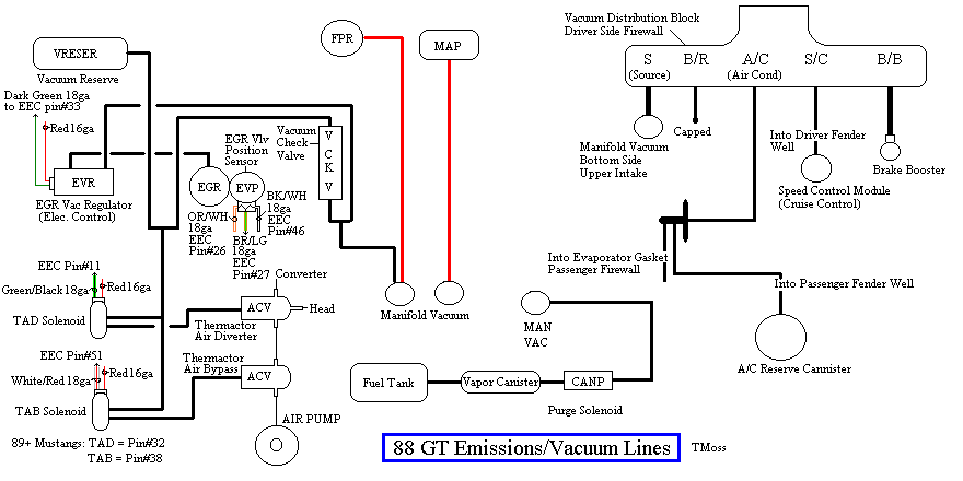
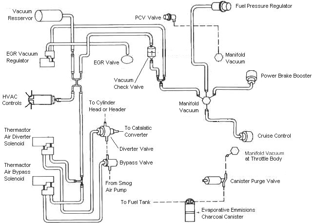
Read the how it works below and then apply what you have learned using the vacuum system diagram. You obviously have some of the vacuum lines misconnected.
Some basic theory to clarify how things work is in order…
EGR System theory and testing
Revised 29-Sep-2013 to add code definitions for EGR sensor and EVR regulator.
The EGR shuts off at Wide Open Throttle (WOT), so it has minimal effect on performance. The addition of exhaust gas drops combustion temperature, increases gas mileage and reduces the tendency of the engine to ping. It can also reduce HC emissions by reducing fuel consumption. The primary result of EGR usage is a reduction in NOx emissions. It does this by reducing the amount of air/fuel mixture that gets burned in the combustion process. Less air from the intake system means less air to mx with the fuel, so the computer leans out the fuel delivery calculations to balance things out. This reduces combustion temperature, and the creation of NOx gases. The reduced combustion temp reduces the tendency to ping.
The computer shuts down the EGR system when it detects WOT (Wide Open Throttle), so the effect on full throttle performance is too small to have any measurable negative effects.
The EGR system has a vacuum source (line from the intake manifold) that goes to the EVR, computer operated electronic vacuum regulator. The EVR is located on the back of the passenger side shock strut tower. The computer uses RPM, Load. and some other factors to tell the EVR to pass vacuum to open the EGR valve. The EGR valve and the passages in the heads and intake manifold route exhaust gas to the EGR spacer (throttle body spacer). The EGR sensor tells the computer how far the EGR valve is open. Then computer adjusts the signal sent to the EVR to hold, increase or decrease the vacuum. The computer adds spark advance to compensate for the recirculated gases and the slower rate they burn at.
The resistor packs used to fool the computer into turning off the CEL (Check Engine Light) off are a bad idea. All they really do is mess up the data the computer uses to calculate the correct air/fuel mixture. You can easily create problems that are difficult to pin down and fix.
Troubleshooting:
There should be no vacuum at the EGR valve when at idle. If there is, the EVR (electronic vacuum regulator) mounted on the backside of the passenger side wheelwell is suspect. Check the vacuum line plumbing to make sure the previous owner didn’t cross the vacuum lines.
Diagram courtesy of Tmoss & Stang&2birds. (the diagram says 88 GT, but the EGR part is the same for 86-93 Mustangs)
The EGR sensor is basically a variable resistor, like the volume control on a radio. One end is 5 volt VREF power from the computer (red/orange wire). One end is computer signal ground (black/white), and the middle wire (brown/lt green) is the signal output from the EGR sensor. It is designed to always have some small voltage output from it anytime the ignition switch is the Run position. That way the computer knows the sensor & the wiring is OK. No voltage on computer pin 27 (brown/lt green wire) and the computer thinks the sensor is bad or the wire is broken and sets code 31. The voltage output can range from approximately .6-.85 volt. A defective or missing sensor will set codes 31 (EVP circuit below minimum voltage) or 32 ( EGR voltage below closed limit).
The EVR regulates vacuum to the EGR valve to maintain the correct amount of vacuum. The solenoid coil should measure 20-70 Ohms resistance. The regulator has a vacuum feed on the bottom which draws from the intake manifold. The other vacuum line is regulated vacuum going to the EGR valve. One side of the EVR electrical circuit is +12 volts anytime the ignition switch is in the run position. The other side of the electrical circuit is the ground path and is controlled by the computer. The computer switches the ground on and off to control the regulator solenoid. A defective EVR will set codes 33 (insufficient flow detected), 84 (EGR Vacuum Regulator failure – Broken vacuum lines, no +12 volts, regulator coil open circuit, missing EGR vacuum regulator.)
EGR test procedure courtesy of cjones
To check the EGR valve:
Bring the engine to normal temp.
Connect a vacuum pump to the EGR Valve or
see the EGR test jig drawing below. Connnect the test jig or to directly to manifold vacuum.
Do not connect the EGR test jig to the EVR (Electronic Vacuum Regulator).
Apply 5in vacuum to the valve.
Using the test jig, use your finger to vary the vacuum
If the engine stumbled or died then EGR Valve and passage(there is a passageway through the heads and intake) are good.
If the engine did NOT stumble or die then either the EGR Valve is bad and/or the passage is blocked.
If the engine stumbled,
connect EGR test jig to the hose coming off of the EGR Valve.
Use your finger to cap the open port on the vacuum tee.
Snap throttle to 2500 RPM (remember snap the throttle don't hold it there).
Did the vacuum gauge show about 2-5 in vacuum?
If not the EVR has failed
EGR test jig
To test the computer and wiring to the computer, you can use a test light across the EVR wiring connectors and dump the codes. When you dump the codes, the computer does a self test that toggles every relay/actuator/solenoid on and off. When this happens, the test light will flicker. If the test light remains on the computer or the wiring is suspect.
To check the EVR to computer wiring, disconnect the EVR connector and connect one end of the Ohmmeter to the dark green wire EVR wiring. Remove the passenger side kick panel and use a 10 MM socket to remove the computer connector from the computer. Set the Ohmmeter to high range and connect the other ohmmeter lead to ground. You should see an infinite open circuit indication or a reading greater than 1 Meg Ohm. If you see less than 200 Ohms, the dark green wire has shorted to ground somewhere.
Diagrams courtesy of Tmoss & Stang&2birds
Vacuum diagram 89-93 Mustangs
Fix what is misconnected and then clear the codes and dump them again. If you are still getting 34 & 84 codes, repost.
See the following website for some help from Tmoss (diagram designer) & Stang&2Birds (website host) for help on 88-95 wiring
http://www.veryuseful.com/mustang/tech/engine/ Everyone should bookmark this site.
Complete computer, actuator & sensor wiring diagram for 91-93 Mass Air Mustangs
http://www.veryuseful.com/mustang/tech/engine/images/91-93_5.0_EEC_Wiring_Diagram.gif
Complete computer, actuator & sensor wiring diagram for 88-91 Mass Air Mustangs
http://www.veryuseful.com/mustang/tech/engine/images/88-91_5.0_EEC_Wiring_Diagram.gif
Ignition switch wiring
http://www.veryuseful.com/mustang/tech/engine/images/IgnitionSwitchWiring.gif
Fuel, alternator, A/C and ignition wiring
http://www.veryuseful.com/mustang/tech/engine/images/fuel-alt-links-ign-ac.gif
O2 sensor wiring harness
http://www.veryuseful.com/mustang/tech/engine/images/mustangO2Harness.gif
Vacuum diagram 89-93 Mustangs
http://www.veryuseful.com/mustang/tech/engine/images/mustangFoxFordVacuumDiagram.jpg
HVAC vacuum diagram
http://www.veryuseful.com/mustang/tech/engine/images/Mustang_AC_heat_vacuum_controls.gif
TFI module differences & pin out
http://www.veryuseful.com/mustang/tech/engine/images/TFI_5.0_comparison.gif
Fuse box layout
http://www.veryuseful.com/mustang/tech/engine/images/MustangFuseBox.gif
87-92 power window wiring
http://www.veryuseful.com/mustang/tech/engine/images/mustang87-92 PowerWindowWiring.gif
93 power window wiring
http://www.veryuseful.com/mustang/tech/engine/images/mustang93PowerWindows.gif
T5 Cutaway showing T5 internal parts
http://www.veryuseful.com/mustang/tech/engine/images/5_Speed_Cutaway_Illustrated.jpg
Visual comparison of the Ford Fuel Injectors, picture by TMoss:
http://www.veryuseful.com/mustang/tech/engine/images/Ford_Injector_Guide.jpg