You guys with idle/stall problems could save a lot of time chasing your tails if you would go through the
Surging Idle Checklist. Over 50 different people contributed information to it. The
first two posts have all the fixes, and steps through the how to find and fix your idle problems without spending a lot of time and money. I continue to update it as more people post fixes or ask questions. You can post questions to that sticky and have your name and idle problem recognized. The guys with original problems and fixes get their posts added to the main fix.

It's free, I don't get anything for the use of it except knowing I helped a fellow Mustang enthusiast with his car. At last check, it had more than 134,000 hits, which indicates it does help fix idle problems quickly and inexpensively.
Code 41 or 91 Three digit code 172 or 176 - O2 sensor indicates system lean. Look for a vacuum leak or failing O2 sensor.
Revised 29-Sep-2013 to add back in a clogged crossover tube as cause for code 41
Code 41 is a RH side sensor, as viewed from the driver's seat.
Code 91 is the LH side sensor, as viewed from the driver's seat.
Code 172 is the RH side sensor, as viewed from the driver's seat.
Code 176 is the LH side sensor, as viewed from the driver's seat.
The computer sees a lean mixture signal coming from the O2 sensors and tries to compensate by adding more fuel. Many times the end result is an engine that runs pig rich and stinks of unburned fuel.
The following is a Quote from Charles O. Probst, Ford fuel Injection & Electronic Engine control:
"When the mixture is lean, the exhaust gas has oxygen, about the same amount as the ambient air. So the sensor will generate less than 400 Millivolts. Remember lean = less voltage.
When the mixture is rich, there's less oxygen in the exhaust than in the ambient air , so voltage is generated between the two sides of the tip. The voltage is greater than 600 millivolts. Remember rich = more voltage.
Here's a tip: the newer the sensor, the more the voltage changes, swinging from as low as 0.1 volt to as much as 0.9 volt. As an oxygen sensor ages, the voltage changes get smaller and slower - the voltage change lags behind the change in exhaust gas oxygen.
Because the oxygen sensor generates its own voltage, never apply voltage and never measure resistance of the sensor circuit. To measure voltage signals, use an analog voltmeter with a high input impedance, at least 10 megohms. Remember, a digital voltmeter will average a changing voltage." End Quote
Testing the O2 sensors 87-93 5.0 Mustangs
Measuring the O2 sensor voltage at the computer will give you a good idea of how well they are working. You'll have to pull the passenger side kick panel off to gain access to the computer connector. Remove the plastic wiring cover to get to the back side of the wiring. Use a safety pin or paper clip to probe the connections from the rear.
Disconnect the O2 sensor from the harness and use the body side O2 sensor harness as the starting point for testing. Do not measure the resistance of the O2 sensor , you may damage it. Resistance measurements for the O2 sensor harness are made with one meter lead on the O2 sensor harness and the other meter lead on the computer wire or pin for the O2 sensor.
Backside view of the computer wiring connector:
87-90 5.0 Mustangs:
Computer pin 43 Dark blue/Lt green – LH O2 sensor
Computer pin 29 Dark Green/Pink – RH O2 sensor
The computer pins are 29 (LH O2 with a dark green/pink wire) and 43 (RH O2 with a dark blue/pink wire). Use the ground next to the computer to ground the voltmeter. The O2 sensor voltage should switch between .2-.9 volt at idle.
91-93 5.0 Mustangs:
Computer pin 43 Red/Black – LH O2 sensor
Computer pin 29 Gray/Lt blue – RH O2 sensor
The computer pins are 29 (LH O2 with a Gray/Lt blue wire) and 43 (RH O2 with a Red/Black wire). Use the ground next to the computer to ground the voltmeter. The O2 sensor voltage should switch between .2-.9 volt at idle.
Testing the O2 sensors 94-95 5.0 Mustangs
Measuring the O2 sensor voltage at the computer will give you a good idea of how well they are working. You'll have to pull the passenger side kick panel off to gain access to the computer connector. Remove the plastic wiring cover to get to the back side of the wiring. Use a safety pin or paper clip to probe the connections from the rear. The computer pins are 29 (LH O2 with a red/black wire) and 27 (RH O2 with a gray/lt blue wire). Use pin 32 (gray/red wire) to ground the voltmeter. The O2 sensor voltage should switch between .2-.9 volt at idle.
Note that all resistance tests must be done with power off. Measuring resistance with a circuit powered on will give false readings and possibly damage the meter. Do not attempt to measure the resistance of the O2 sensors, it may damage them.
Testing the O2 sensor wiring harness
Most of the common multimeters have a resistance scale. Be sure the O2 sensors are disconnected and measure the resistance from the O2 sensor body harness to the pins on the computer. Using the Low Ohms range (usually 200 Ohms) you should see less than 1.5 Ohms.
87-90 5.0 Mustangs:
Computer pin 43 Dark blue/Lt green – LH O2 sensor
Computer pin 29 Dark Green/Pink – RH O2 sensor
Disconnect the connector from the O2 sensor and measure the resistance:
From the Dark blue/Lt green wire in the LH O2 sensor harness and the Dark blue/Lt green wire on the computer pin 43
From the Dark Green/Pink wire on the RH Os sensor harness and the Dark Green/Pink wire on the computer pin 43
91-93 5.0 Mustangs:
Computer pin 43 Red/Black – LH O2 sensor
Computer pin 29 Gray/Lt blue – RH O2 sensor
Disconnect the connector from the O2 sensor and measure the resistance:
From the Red/Black wire in the LH O2 sensor harness and the Red/Black wire on the computer pin 43
From the Dark Green/Pink Gray/Lt blue wire on the RH Os sensor harness and the Gray/Lt blue wire on the computer pin 29
94-95 5.0 Mustangs:
Computer pin 29 Red/Black – LH O2 sensor
Computer pin 27 Gray/Lt blue – RH O2 sensor
From the Red/Black wire in the LH O2 sensor harness and the Red/Black wire on the computer pin 29
From the Dark Green/Pink Gray/Lt blue wire on the RH Os sensor harness and the Gray/Lt blue wire on the computer pin 27
There is a connector between the body harness and the O2 sensor harness. Make sure the connectors are mated together, the contacts and wiring are not damaged and the contacts are clean and not coated with oil.
The O2 sensor ground (orange wire with a ring terminal on it) is in the wiring harness for the fuel injection wiring. I grounded mine to one of the intake manifold bolts
Make sure you have the proper 3 wire O2 sensors. Only the 4 cylinder cars used a 4 wire sensor, which is not compatible with the V8 wiring harness.
Replace the O2 sensors in pairs if replacement is indicated. If one is weak or bad, the other one probably isn't far behind.
Code 41 can also be due to carbon plugging the driver’s side Thermactor air crossover tube on the back of the engine. The tube fills up with carbon and does not pass air to the driver’s side head ports, Remove the tube and clean it out so that both sides get good airflow: this may be more difficult than it sounds. You need something like a mini rotor-rooter to do the job because of the curves in the tube. Something like the outer spiral jacket of a flexible push-pull cable may be the thing that does the trick.
If you get only code 41 and have changed the sensor, look for vacuum leaks. This is especially true if you are having idle problems. The small plastic tubing is very brittle after many years of the heating it receives. Replace the tubing and check the PVC and the hoses connected to it.
Code 67 –
Revised 2 Nov 2012 to add definition of the NSS functions for both 5 speed and auto transmissions
Cause of problem:
clutch not depressed (5 speed) or car not in neutral or park (auto) or A/C in On position when codes where dumped. Possible neutral safety switch or wiring problem. This code may prevent you from running the Key On Engine On tests.
External evidence from other sources claims that a code 67 can cause an idle surge condition. Do try to find and fix any issues with the switch and wiring if you get a code 67.
What the NSS (Neutral Safety Switch) does:
5 speed transmission: It has no connection with the starter, and the engine can be cranked without it being connected.
Auto transmission: It is the safety interlock that prevents the starter from cranking the engine with the transmission in gear.
What it does for both 5 speed and auto transmission cars:
The computer wants to make sure the A/C is off due to the added load on the engine for the engine running computer diagnostic tests. It also checks to see that the transmission is in Neutral (5 speed and auto transmission) and the clutch depressed (T5, T56, Tremec 3550 & TKO)). This prevents the diagnostics from being run when the car is driven. Key On Engine Running test mode takes the throttle control away from the driver for several tests. This could prove hazardous if the computer was jumpered into test mode and then driven.
The following is for 5 speed cars only.
The NSS code 67 can be bypassed for testing. You will need to temporarily ground computer pin 30 to the chassis. Computer pin 30 uses a Lt blue/yellow wire. Remove the passenger side kick panel and then remove the plastic cover from the computer wiring connector. Use a safety pin to probe the connector from the rear. Jumper the safety pin to the ground near the computer.
Be sure to remove the jumper BEFORE attempting to drive the car!!!
Finding vacuum leaks
Revised 04-Aug-2011 to add pintle cap, PCV grommet & power brake check valve grommet to checklist.
There is no easy way to find vacuum leaks. It is a time consuming job that requires close inspection of each and every hose and connection.
Small vacuum leaks may not show much change using a vacuum gauge. The range of "good readings" varies so much from engine to engine that it may be difficult to detect small leaks. The engine in my first Mustang pulled about 16.5" of vacuum at 650-725 RPM, which I consider rather low. It was a mass market remanufactured rebuild, so no telling what kind of camshaft it had. Average readings seem to run 16"-18" inches at idle and 18"-21" at 1000 RPM. The only sure comparison is a reading taken when your car was performing at its best through all the RPM ranges and what it is doing now. Use one of the spare ports on the vacuum tree that is mounted on the firewall near the windshield wiper motor.
Use a squirt can of motor oil to squirt around the mating surfaces of the manifold & TB. The oil will be sucked into the leaking area and the engine will change speed.
Avoid using flammable substitutes for the oil such as propane or throttle body cleaner. Fire is an excellent hair removal agent, and no eyebrows is not cool...
The vacuum line plumbing is old and brittle on many of these cars, so replacing the lines with new hose is a good plan. The common 1/8” and ¼” vacuum hose works well and isn’t expensive.
The PCV grommet and the power brake booster check valve grommet are two places that often get overlooked when checking for vacuum leaks. The rubber grommets get hard and lose their ability to seal properly. The PVC grommet is difficult to see if it is correctly seated and fitting snugly.
Fuel injector O rings can get old and hard. When they do, they are prone to leaking once the engine warms up. This can be difficult to troubleshoot, since it is almost impossible to get to the injectors to squirt oil into the fuel injector mounting bosses. If the plastic caps on the fuel injectors (pintle caps) are missing, the O rings will slide off the injectors and fall into the intake manifold.
Fuel injector seal kits with 2 O rings and a pintle cap (Borg-Warner P/N 274081) are available at Pep Boys auto parts. Cost is about $3-$4 per kit. The following are listed at the Borg-Warner site (
http://www.borg-warner.com ) as being resellers of Borg-Warner parts:
http://www.partsplus.com/ or
http://www.autovalue.com/ or
http://www.pepboys.com/ or
http://www.federatedautoparts.com/
Most of the links above have store locators for find a store in your area.
Use motor oil on the O rings when you re-assemble them & everything will slide into place. The gasoline will wash away any excess oil that gets in the wrong places and it will burn up in the combustion chamber. Heat the pintle caps in boiling water to soften them to make them easier to install.
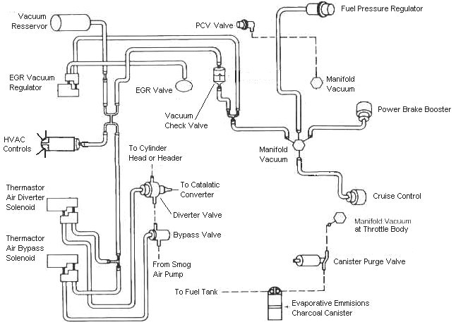
Diagram courtesy of Tmoss & Stang&2birds
Vacuum leak due to slipped lower intake manifold gasket...
Ask Nicoleb3x3 about the intake gasket that slipped out of place and caused idle and vacuum leak problems that could not be seen or found by external examination. I don't care what you spray with, you won't find the leak when it is sucking air from the lifter valley. It simply isn't possible to spray anything in there with the lower manifold bolted in place.
See the following website for some help from Tmoss (diagram designer) & Stang&2Birds (website host) for help on 88-95 wiring
http://www.veryuseful.com/mustang/tech/engine/ Everyone should bookmark this site.
Ignition switch wiring
http://www.veryuseful.com/mustang/tech/engine/images/IgnitionSwitchWiring.gif
Fuel, alternator, A/C and ignition wiring
http://www.veryuseful.com/mustang/tech/engine/images/fuel-alt-links-ign-ac.gif
Complete computer, actuator & sensor wiring diagram for 88-91 Mass Air Mustangs
http://www.veryuseful.com/mustang/tech/engine/images/88-91_5.0_EEC_Wiring_Diagram.gif
Vacuum diagram 89-93 Mustangs
http://www.veryuseful.com/mustang/tech/engine/images/mustangFoxFordVacuumDiagram.jpg
HVAC vacuum diagram
http://www.veryuseful.com/mustang/tech/engine/images/Mustang_AC_heat_vacuum_controls.gif
TFI module differences & pinout
http://www.veryuseful.com/mustang/tech/engine/images/TFI_5.0_comparison.gif
Fuse box layout
http://www.veryuseful.com/mustang/tech/engine/images/MustangFuseBox.gif