There is more elecrical work to
properly convert an EFI car to carb than to fix what you have.
FYI: here are some of the things needed for an EFI to carb conversion.
A word of warning on EFI to carb swaps: don’t expect to pass emissions in any state that does comprehensive smog inspections, because it won’t happen. Be aware that you are violating several Federal laws concerning the removal of pollution control equipment. If you operate the vehicle on public highways and get caught by the Feds (doubtful, but possible) you could be subject to fines and imprisonment. You won't get any more power from a carb than you will from EFI.
The following information is intended for informational purposes only. Operation of a motor vehicle modified in such as manner as described below should be limited to off road use only.
Doing the swap: You must know how to read electrical diagrams and wire circuits properly to do the swap. Don’t take shortcuts or cut corners in the fabrication of the electrical or mechanical assemblies. If you do NASCAR quality work, the car will look good, run good and be as reliable as a carb’d car can be. Take pride in a job done with excellence.
If you are one of those few people who do excellent work, please disregard my negative comments. They are not intended for you.
Quality, quality, quality…
Some of the motivation of my negative comments about carb to EFI has to do with the quality of electrical workmanship. A lot of the wiring “repairs” that I have seen on the road and in the junkyard looks like road kill. The other part of my negative view stems from people who can’t grasp the operation and tuning of EFI. Carbs have their own set of requirements and some learning is required to get the best performance. Every car is different and each installation needs to be tuned to get the best performance. Putting an “out of the box carb” or one from someone else’s car isn’t the way to success. There is no auto compensation for small variations in carbs like there is for EFI. Just throwing a carb on a car because you won’t bother to learn how EFI works is a poor excuse.
Now that the rant is over, here’s some practical advice…
Do not use an EFI in tank fuel pump with a carb. You will never get the pressure/flow regulated properly. Either go full EFI or use a tank/fuel pump/fuel lines out of an 84 or earlier Stang. Fabricating your own setup is possible but there are some snags to overcome.
Do not attempt to leave the EFI in place in an attempt to control either the electric fuel pump or ignition. Doing so qualifies you for the “Road Kill Mechanics Award”.
If you try to use your current tank, you will need to pull the fuel pump out and fabricate a pickup tube & strainer sock to replace the fuel pump. Or you can have a sump fabricated and welded onto you existing tank. Many welding shops will not weld fuel tanks because of the dangers involved if the tank isn't purged properly.
You will need an external electric fuel pump unless you change the timing cover for one with the mechanical fuel pump mount on it. Rip all the EFI wiring out, and the computer controlled fuel pump won't work. You will need to add a relay & switch and wire in the existing inertia switch for an external low pressure electric fuel pump. Do not try to wire the fuel pump without the relay. The 15-20 amps the pump pulls will overload the circuit. This will take power away from other items on the same circuit or cause the fuse or fuse link to blow.
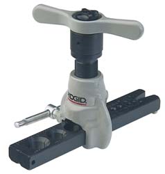
You will need to run some new fuel feed lines or braided hose. The 3/8" aluminum tubing works well, but you will need a flaring tool and bending springs to fabricate the lines. Braided hose is easy to run and route, but is much more expensive. It is about $3.50-$4.00 a foot plus the end fittings, which are $3-$4 each. Fabricating hose assembles can be difficult, but anyplace that makes hydraulic hoses can do it for you for an extra charge. See
http://www.amazonhose.com for more information.
For stainless steel braided hose and fittings for automotive use:
See
http://store.summitracing.com/egnse...el+hose&searchinresults=false&N=+115&y=6&x=23
http://www.jegs.com/webapp/wcs/stor...hall&searchTerm=stainless+steel+hose&x=18&y=4
See
http://www.aeroquip.com/pages/performance.html for more information on High performance automotive hose products
AN fittings require a 37 degree flaring tool. A standard automotive or household plumbing tool is 45 degrees and cannot be used with AN flare fittings. If you do, the flare is subjected to too much stress when the fitting is tightened, and is likely to fail or leak.
See
http://www.mscdirect.com/ ,
http://www.mcmaster.com/ or for the flaring tool you will need . Prices start at $75 and go up
http://www1.mscdirect.com/CGI/N2DRVSH?PACACHE=000000013509163
http://www.mcmaster.com/ctlg/DisplCtlgPage.aspx?ReqTyp=CATALOG&CtlgPgNbr=2252&term=Flaring
While you are at the electrical part, you'll need a Durspark or similar ignition system. The 85 Mustang GT 5 speed has a suitable Duraspark distributor with a steel gear compatible with the roller camshaft. The EFI ignition depends on the EFI sensors to advance the spark. Rip out the TPS and MAP/Baro sensors and the computer will have no idea of the proper ignition timing for best performance. Running a fixed timing setting is only for test purposes or for a race track only car. Don't try it on the street: the results will not be nearly as good as a properly setup Durspark or equal. Crane makes a really nice distributor for non-EFI applications. . See
http://www.cranecams.com/index.php?show=browseParts&lvl=4&prt=127 for more information.
Tools needed:
Crimp tool for connector pins $9-$30 AutoZone, NAPA, Advance Auto Parts or other store
100-150 watt soldering gun (recommend WELLER 8200PK soldering gun kit 100/140W) $30 at Lowes or $40 at Home Depot
3/32”-1/8”
rosin core electrical solder, 1/4 lb roll $6 at Ace Hardware, Home Depot or Lowes
Assorted sizes of heat shrink tubing. Buy long pieces and cut length to fit. It is cheaper that way.
http://www.partsexpress.com/webpage.cfm?&WebPage_ID=346&CFID=169547&CFTOKEN=34300345
Hot air gun to shrink the tubing ($30-$40) Home Depot
Jeweler’s screwdriver kit $5 at Ace Hardware
Assorted automotive wire, 18-16 gauge 10’-20’ foot spools in different colors. $5 a roll at Advance Auto Parts.
Ford connector pins AutoZone, NAPA or other store $5-$10 for a kit of 10-12 assorted pins
You will have $110-$150 in materials and tools if you don't already have them.
The water temp and oil pressure signals feed from the sender to the main harness through the 10 pin EFI engine harness. To utilize these senders, you need to identify the wires and find a way to reconnect them to the main harness after the EFI engine harness is removed. You need a weatherproof quick connector to join the sender wiring to the main harness.
You will need to construct a wiring harness from the ‘85 carb distributor to the Duraspark box if you go Duraspark, or other distributor to coil wiring.
The voltmeter picks up its signal from the switched voltage present on the instrument panel, so you don’t need to worry about that.
The fuel tank gauge is also independent of the computer wiring.
AutoZone wiring diagrams
http://www.autozone.com/servlet/UiB..._us/0900823d/80/16/71/3c/0900823d8016713c.jsp for 79-88 model Mustangs
http://www.autozone.com/servlet/UiB..._us/0900823d/80/19/59/5a/0900823d8019595a.jsp for 89-93 model Mustangs
http://www.autozone.com/servlet/UiB..._us/0900823d/80/1d/db/3c/0900823d801ddb3c.jsp for 94-98 model Mustangs
How to solder like a pro -
http://fordfuelinjection.com/?p=7 a must read for any automotive wiring job.
Soldering pigtails onto existing pins is road kill quality work as far as I am concerned. Take some time to study the way the Ford connectors are assembled and you will find that a small jeweler’s screwdriver will release the pins from the connector shell. New pins and a crimping tool are available from the Standard Motor Parts or Bendix Electrical parts line that the NAPA & Bumper to Bumper Auto Parts stores carry. Ask any auto parts store about Standard Motor Products or Bendix Electrical wiring parts. Those that carry them will be able to get the parts you need. AutoZone has a cheap kit with 10 pins for about $5. Just enough pins to leave you short when assembling a connector.
One of the interesting things about the Ford OEM wiring diagrams is that the connector shape on the drawing matches the connector shape in the car. That makes it easier to identify connectors and circuits. OEM Ford diagrams are available at for an 85 Mustang at
http://www.helminc.com/helm/Result....edia=&mscsid=2M838NG3R5SR2MCS00A3HVE05T03C501 or can be found in the Chilton series of auto repair manuals for Mustangs.
The following is an excellent idea from a fellow Stangnetter who tackled the wiring plan the right way. He obtained the wiring diagrams from an 85 carb'd V8 Mustang and laid them out side by side with the diagrams from his car. He then traced out each circuit and the wire colors and connectors associated with them. After tracing the circuit and connectors for a circuit, he laid out the changes he needed to make. One circuit at a time made a difficult big job into many smaller easy to manage jobs.