No Start/ Injector Noise?

Oct 30, 2011
45
0
6
i recently changed my lower intake manifold gaskets and injector o-rings because they were leaking. as i got done i checked, and double checked everything was connected right. i started it and it sounded funky with a poping like backfire but not very loud. it was on for like 20 seconds and i decided to turn it off because it didnt sound right. i when to try and start it and it cranks fine but wont start. after im done cranking it it sounds like it wants to start and making some combustion. also at the injectors, it makes a loud noise when priming the system???
 
Cranks OK, but No Start Checklist for Fuel Injected Mustangs

A word about this checklist before you start: it is arranged in a specific order to put the most likely failure items first. That will save you time, energy and money. Start at the top of the list and work your way down. Jumping around will possibly cause you to miss just what you need to see to find and fix the problem. Don’t skip any steps because the next step depends on the last step working correctly.


Revised 12-Dec-2011 to replace 10 pin salt & pepper connector graphic.

All text applies to all models unless stated otherwise.

Note: 94-95 specific changes are in red

1.) Remove push on connector (small red/blue wire) from starter solenoid and turn ignition switch to the Run position. Place car in neutral or Park and set the parking brake. Remove the coil wire from distributor & and hold it 3/8” away from the engine block. Jumper the screw to the big bolt on the starter solenoid that has the battery wire connected to it. You should get a nice fat blue spark.
Most of the items are electrical in nature, so a test light, or even better, a voltmeter, is helpful to be sure they have power to them.

No spark, possible failed items in order of their probability:
A.) MSD or Crane ignition box if so equipped
B.) PIP sensor in distributor. The PIP sensor supplies the timing pulse to trigger the TFI and injectors. A failing PIP sensor will sometimes let the engine start if the SPOUT is removed. See paragraph 5A – Using a noid light will tell if the PIP is working by flashing when the engine is cranking.
C.) TFI module: use a test light to check the TFI module. Place one lead of the test light on the red/green wire on the ignition coil connector and the other lead on the dark green/yellow wire on the ignition coil connector. If the TFI is working properly, the test light will flash when the engine is cranked using the ignition switch.
D.) Coil
E.) No EEC or computer power - EEC or computer relay failure
86-93 models only: EEC relay next to computer - look for 12 volts at the fuel injector red wires.
94-95 models only: EEC or PCM power relay in the constant control relay module. Look for 12 volts at the fuel injector red wires.
Both 86-93 and 94-95 models: No 12 volts with the ignition switch in the run position on the fuel injector red wires. The relay has failed or there is no power coming from the ignition switch. Make sure that there is 12 volts on the red/green wire on the coil before replacing the relay.
F.) No EEC or computer power - fuse or fuse link failure
86-93 models only: Fuse links in wiring harness - look for 12 volts at the fuel injector red wires. All the fuse links live in a bundle up near the starter solenoid. Look for a 20 gauge blue fuse link connected to 2 black/orange 14 gauge wires.
94-95 models only: 20 amp EEC fuse in the engine compartment fuse box. Look for 12 volts at the fuel injector red wires.
G.) Ignition switch - look for 12 volts at the ignition coil red/lt green wire. No 12 volts, blown fuse link or faulty ignition switch. Remove the plastic from around the ignition switch and look for 12 volts on the red/green wire on the ignition switch with it in the Run position. No 12 volts and the ignition switch is faulty. If 12 volts is present in the Run position at the ignition switch but not at the coil, then the fuse or fuse link is blown.
Note: fuses or fuse links blow for a reason. Don’t replace either a fuse or fuse link with one with a larger rating than stock. Doing so invites an electrical fire.
Ignition fuse links may be replaced with an inline fuse holder and 5 amp fuse for troubleshooting purposes.
94-95 models only: Check inside fuse panel for fuse #18 blown – 20 amp fuse
H.) Missing or loose computer power ground. The computer has its own dedicated power ground that comes off the ground pigtail on the battery ground wire. Due to it's proximity to the battery, it may become corroded by acid fumes from the battery.
In 86-90 model cars, it is a black cylinder about 2 1/2" long by 1" diameter with a black/lt green wire.
In 91-95 model cars it is a black cylinder about 2 1/2" long by 1" diameter with a black/white wire.
You'll find it up next to the starter solenoid where the wire goes into the wiring harness
I.) Computer.
J.) Bad or missing secondary power ground. It is located between the back of the intake manifold and the driver's side firewall. It supplies ground for the alternator, A/C compressor clutch and other electrical accessories such as the gauges.
K.) Engine fires briefly, but dies immediately when the key is released to the Run position. Crank the engine & when it fires off, pull the small push on connector (red wire) off the starter relay (Looks like it is stuck on a screw). Hold the switch in the crank position: if it continues to run there is a problem with either the ignition switch or TFI module. Check for 12 volts at the red/green wire on the coil with the switch in the Run position. Good 12 volts, then replace the TFI. No 12 volts, replace the ignition switch.

Wiring Diagrams:

See the following website for some help from Tmoss (diagram designer) & Stang&2Birds (website host) for help on 88-95 wiring Mustang FAQ - Engine Information Everyone should bookmark this site.

Ignition switch wiring
http://www.veryuseful.com/mustang/tech/engine/images/IgnitionSwitchWiring.gif

Fuel, alternator, A/C and ignition wiring
http://www.veryuseful.com/mustang/tech/engine/images/fuel-alt-links-ign-ac.gif

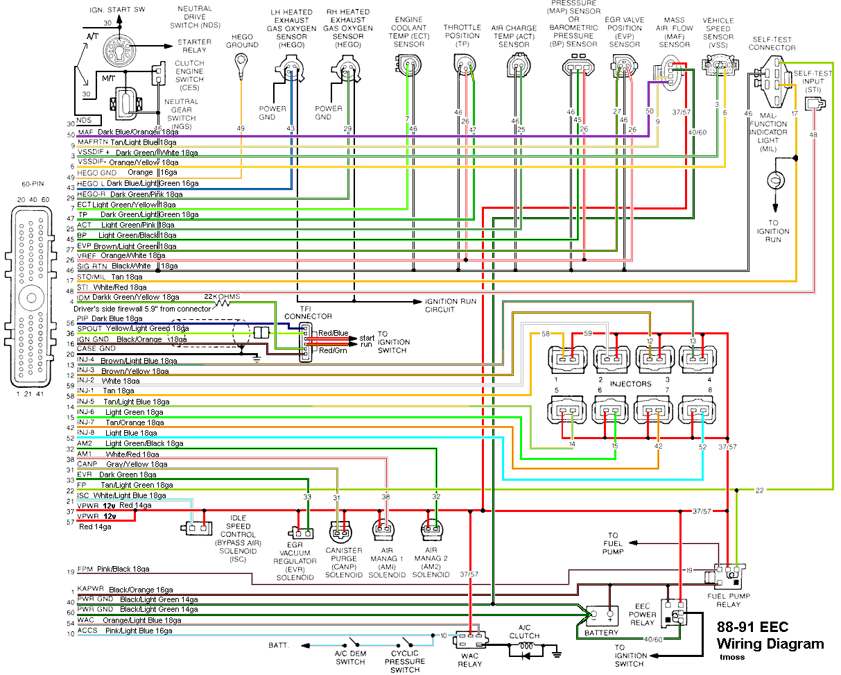
Complete computer, actuator & sensor wiring diagram for 88-91 Mass Air Mustangs
http://www.veryuseful.com/mustang/tech/engine/images/88-91_5.0_EEC_Wiring_Diagram.gif

Complete computer, actuator & sensor wiring diagram for 91-93 Mass Air Mustangs
http://www.veryuseful.com/mustang/tech/engine/images/91-93_5.0_EEC_Wiring_Diagram.gif

Complete computer, actuator & sensor wiring diagram for 94-95 Mass Air Mustangs
http://www.veryuseful.com/mustang/tech/engine/images/94-95_5.0_EEC_Wiring_Diagram.gif


AutoZone wiring diagrams: You can navigate to the diagrams yourself via Repair Info | AutoZone.com and select the car year, make, model and engine. That will enable you to bring up the wiring diagram for your particular car.

2.) Spark at coil wire, pull #1 plug wire off at the spark plug and check to see spark. No spark, possible failed items in order of their probability: [/b]
A.) Moisture inside distributor – remove cap, dry off & spray with WD40
B.) Distributor cap
C.) Rotor
D.) Spark Plug wires
E.) Coil weak or intermittent - you should see 3/8" fat blue spark with a good coil

3.) Spark at spark plug, but no start.
Next, get a can of starting fluid (ether) from your local auto parts store: costs a $1.30 or so. Then pull the air duct off at the throttle body elbow, open the throttle, and spray the ether in it. Reconnect the air duct and try to start the car. Do not try to start the car without reconnecting the air duct.

Two reasons:
1.) If it backfires, the chance for a serious fire is increased.
2.) On Mass Air cars, the computer needs to measure the MAF flow once the engine starts.
If it starts then, you have a fuel management issue. Continue the checklist with emphasis of fuel related items that follow. If it doesn’t, then it is a computer or timing issue: see Step 4.

Clue – listen for the fuel pump to prime when you first turn the ignition switch on. It should run for 2-4 seconds and shut off. To trick the fuel pump into running, find the EEC test connector and jump the connector in the Upper RH corner to ground. The EEC connector is near the wiper motor and LH hood hinge.

attachment.php


If the relay & inertia switch are OK, you will have power to the pump. Check fuel pressure – remove the cap from the Schrader valve behind the alternator and depress the core. Fuel should squirt out, catch it in a rag. Beware of fire hazard when you do this. In a pinch, you can use a tire pressure gauge to measure the fuel pressure. It may not be completely accurate, but you will have some clue as to how much pressure you have. If you have any doubts about having sufficient fuel flow/pressure, rent a fuel pressure test gauge from the auto parts store. That will tell you for sure if you have adequate fuel pressure.


4.) No fuel pressure, possible failed items in order of their probability:
A.) Tripped inertia switch – Coupe & hatch cars hide it under the plastic trim covering the driver's side taillight. Use the voltmeter or test light to make sure you have power to both sides of the switch
B.) Fuel pump power relay – located under the driver’s seat in most stangs built before 92. On 92 and later model cars it is located below the Mass Air Flow meter. Look for 12 volts at the Pink/Black wire on the fuel pump relay.
C.) Clogged fuel filter
D.) Failed fuel pump
E.) 86-90 models only: Blown fuse link in wiring harness. Look for 12 volts at the Orange/Lt Blue wire on the fuel pump relay.
91-93 models only Blown fuse link in wiring harness. Look for 12 volts at the Pink/Black wire on the fuel pump relay.
The fuse links for all model years 86-93 live in the wiring harness near the starter solenoid.
94-95 models only: 20 amp fuel pump fuse in the engine compartment fuse box. Look for 12 volts at the Dark green/yellow wire on the constant control relay module.
F.) Engine seem to load up on fuel and may have black smoke at the tailpipe. Fuel pressure regulator failed. Remove the vacuum line from the regulator and inspect for fuel escaping while the pump is running. If fuel is coming out the vacuum port, the regulator has failed. Check the regulator vacuum line for fuel too. Disconnect it from the engine and blow air though it. If you find gas, the regulator has failed.

5.) Fuel pressure OK, the injectors are not firing.
A.) The PIP sensor in the distributor tells the computer when to fire the injectors. A failing PIP sensor will sometimes let the engine start if the SPOUT is removed.
A noid light available from any auto parts store, is one way to test the injector circuit to see if the injectors are firing. The noid light plugs into the fuel injector harness in place of any easily accessible injector. Plug it in and try to start the engine: it will flash if the injector is firing.
B.) I like to use an old injector with compressed air applied to the injector where the fuel rail would normally connect. I hook the whole thing up, apply compressed air to the injector and stick it in a paper cup of soapy water. When the engine cranks with the ignition switch on, if the injector fires, it makes bubbles. Cheap if you have the stuff laying around, and works good too.
D.) Pull an injector wire connector off and look for 12 volts on the red wire when the ignition switch is on.
E.) No power, then look for problems with the 10 pin connecter (salt & pepper shakers at the rear of the upper manifold).

See the graphic for the 10 pin connector circuit layout.
salt-pepper-10-pin-connectors-65-jpg.68512

The injector power pin is the VPWR pin in the black 10 pin connector.


F.) No power and the 10 pin connections are good: look for broken wiring between the orange/black wire on the EEC relay and the red wire for the 10 pin connectors.
G.) TPS voltage exceeds 3.7 volts with the throttle closed. This will shut off the injectors, since the computer uses this strategy to clear a flooded engine. Use a DVM, a pair of safety pins, and probe the black/white and green wires to measure the TPS voltage.
On a 94-95 Mustang, probe the black/white and grey/white wires to measure the TPS voltage.
It should be .5-.1.0 volts with the key on, engine not running. Note that if the black/white wire (signal ground) has a bad connection, you will get some strange readings. Make a second measurement using the battery post as the ground to eliminate any ground problems. If the readings are different by more than 5%, you may have a high resistance condition in the black/white signal ground circuit.

6.) Spark & fuel pressure OK.
A.) Failed IAB or improperly set base idle (no airflow to start engine). Press the throttle ¼ way down and try to start the car. See the "Surging Idle Checklist for help with all your idle/stall problems.
B.) Failed computer (not very likely)
C.) Engine ignition or cam timing off: only likely if the engine has been worked on recently. If you removed the distributor, there is a good probability that you installed it 180 degrees out of time.
D.) Firing order off: HO & 351 use a different firing order from the non HO engines.
HO & 351W 1-3-7-2-6-5-4-8
Non HO 1-5-4-2-6-3-7-8
E.) No start when hot - Press the throttle to the floor & try starting it if you get this far. If it starts, replace the ECT.
F. ) Engine that has had the heads off or valves adjusted. Do a compression test to make sure the valves are not adjusted too tight. You should have a minimum of 90 PSI on a cold engine.
 
i checked about 3/4 on the list and after going back i though it could be my distributor because i took it out. i made sure it was set correctat tdc and it started fine after but had a rough idle at the begining then smoothed out on its own. turn it off. go to turn it back on and now wont start??
 
i checked about 3/4 on the list and after going back i though it could be my distributor because i took it out. i made sure it was set correctat tdc and it started fine after but had a rough idle at the begining then smoothed out on its own. turn it off. go to turn it back on and now wont start??
Go through the list again. You are there and I'm not there to see what you did.

Putting the distributor back in and setting the timing.


You can forget about anything beyond this point if you don't have access to a timing light. You will never get the timing set right without one.


Putting the distributor back in is fairly simple. Pull #1 sparkplug, put your finger in the sparkplug hole, crank the engine until you feel compression. Then line up the TDC mark on the balancer with the pointer on the engine block.

The distributor starts out with the #1 plug wire lined up at about 12:00 with you facing it. Align the rotor to about 11:00, since it will turn clockwise as it slides into place.

Align the distributor rotor up with the #1 position marked on the cap, slide the distributor down into the block, (you may have to wiggle the rotor slightly to get the gear to engage) and then note where the rotor is pointing.
If it still lines up with #1 position on the cap, install the clamp and bolt. If not, pull it out and turn 1 tooth forwards or backwards and try again. Put the #1 spark plug back in and tighten it down, put the clamp on the distributor, but don't tighten it too much, as you will have to move the distributor to set the timing. Note that there is no such thing as one tooth off on a 5.0 Mustang. If it doesn't align perfectly with #1 position, you can turn the distributor until it does. The only problem is that if you are too far one way or the other, you can't turn the distributor enough to get the 10-14 degree optimum timing range.


Setting the timing:
Paint the mark on the harmonic balancer with paint -choose 10 degrees BTC or 14 degrees BTC or something else if you have NO2 or other power adder. I try to paint TDC red, 10 degrees BTC white and 14 degrees BTC blue.

10 degrees BTC is towards the drivers side marks.

Note: setting the timing beyond the 10 degree mark will give you a little more low speed acceleration. BUT you will need to run 93 octane to avoid pinging and engine damage. Pinging is very hard to hear at full throttle, so it could be present and you would not hear it.

Simplified diagram of what it looks like. Not all the marks are shown for ease of viewing.

ATC ' ' ' ' ' ' ' ' ' '!' ' ' ' ' ' ' ' ' ' BTC
---------------- > Direction of Rotation as viewed standing in front of the engine.

The ' is 2 degrees.
The ! is TDC
The ' is 10 degrees BTC
Set the timing 5 marks BTC. Or if you prefer, 5 marks towards the driver's side to get 10 degrees.

To get 14 degrees, set it 7 marks BTC. Or if you prefer, 7 marks towards the driver's side to get 14 degrees.

The paint marks you make are your friends if you do it correctly. They are much easier to see that the marks machined into the harmonic balancer hub.

At this point hook up all the wires, get out the timing light. Connect timing light up to battery & #1 spark plug. Then start the engine.

Remove the SPOUT connector (do a search if you want a picture of the SPOUT connector) It is the 2 pin rectangular plug on the distributor wiring harness. Only the EFI Mustang engines have a SPOUT. If yours is not EFI, check for a SPOUT: if you don’t find one, skip any instructions regarding the SPOUT
Warning: there are only two places the SPOUT should be when you time the engine. The first place is in your pocket while you are setting the timing and the second is back in the harness when you finish. The little bugger is too easy to lose and too hard to find a replacement.

Start engine, loosen distributor hold down with a 1/2" universal socket. Shine the timing light on the marks and turn the distributor until the mark lines up with the edge of the timing pointer. Tighten down the distributor hold down bolt, Replace the SPOUT connector and you are done.

The HO firing order is 1-3-7-2-6-5-4-8.
Non HO firing order is 1-5-4-2-6-3-7-8

attachment.php
 
i got to do all that and fallowed step by step. and didnt work. turns on if i leave it sitting for abour 6 hrs. it will run with a rough idle then smooths out. i go and try nd turn it on again and wont turn on. had a buddy come check it out and timing is good. he said the engine could be flooding and it does smell a lot like gas.?? any ideas. thanx
 
What did you miss or skip? For it to not start, something has to not work. The checklist helps you find what that something is.
 
One non functioning injector would not prevent the engine from starting. It would start, but no idle smoothly.
Did you use a noid light to check for injector pulse (Step B) 1?
 
yeah i had a mechanic check the injectors and they are all functioning. when i picked it up it stalled on me and he got to start it back up by pressing on the gas pedal. i know his knowledge in mustangs is pretty good and highly recomended me to get a tune because of the cam and injectors. and the computer isnt adapting to anything.??​
 
Before you waste any money on a tune, fix any items that pop up as trouble codes. The Mass Air Computers are very Good at accommodating changes in cams, cylinder heads, and intake manifolds.

Dump the codes: Codes may be present even if the Check Engine Light (CEL) isn't on.

Dumping the computer diagnostic codes on 86-95 Mustangs

Revised 26-July-2011. Added need to make sure the clutch is pressed when dumping codes.

Codes may be present even if the check engine light hasn’t come on, so be sure to check for them.

Here's the way to dump the computer codes with only a jumper wire or paper clip and the check engine light, or test light or voltmeter. I’ve used it for years, and it works great. You watch the flashing test lamp or Check Engine Light and count the flashes.

Post the codes you get and I will post 86-93 model 5.0 Mustang specific code definitions and fixes. I do not have a complete listing for 94-95 model 5.0 Mustangs at this time.

Be sure to turn off the A/C, and put the transmission in neutral when dumping the codes. On a manual transmission car, be sure to press the clutch to the floor.
Fail to do this and you will generate a code 67 and not be able to dump the Engine Running codes.

Underhoodpictures007-01.webp


Underhoodpictures010.webp


If your car is an 86-88 stang, you'll have to use the test lamp or voltmeter method. There is no functional check engine light on the 86-88's except possibly the Cali Mass Air cars.

computer-self-test-connector-with-test-lamp-01-65-gif.55020


The STI has a gray connector shell and a white/red wire. It comes from the same bundle of wires as the self test connector.

89 through 95 cars have a working Check Engine light. Watch it instead of using a test lamp.

computer-self-test-connector-with-check-engine-light-01-65-gif.55021


The STI has a gray connector shell and a white/red wire. It comes from the same bundle of wires as the self test connector.


WARNING!!! There is a single dark brown connector with a black/orange wire. It is the 12 volt power to the under the hood light. Do not jumper it to the computer test connector. If you do, you will damage the computer.

What to expect:
You should get a code 11 (two single flashes in succession). This says that the computer's internal workings are OK, and that the wiring to put the computer into diagnostic mode is good. No code 11 and you have some wiring problems. This is crucial: the same wire that provides the ground to dump the codes provides signal ground for the TPS, EGR, ACT and Map/Baro sensors. If it fails, you will have poor performance, economy and driveablity problems

Some codes have different answers if the engine is running from the answers that it has when the engine isn't running. It helps a lot to know if you had the engine running when you ran the test.

Dumping the Engine Running codes: The procedure is the same, you start the engine with the test jumper in place. Be sure the A/C is off, and clutch (if present) is pressed to the floor, and the transmission is in neutral. You'll get an 11, then a 4 and the engine will speed up to do the EGR test. After the engine speed decreases back to idle, it will dump the engine running codes.

Trouble codes are either 2 digit or 3 digit, there are no cars that use both 2 digit codes and 3 digit codes.

Your 86-88 5.0 won't have a working Check Engine Light, so you'll need a test light.
See AutoZone Part Number: 25886 , $10
4


Alternate methods:
For those who are intimidated by all the wires & connections, see Actron® for what a typical hand scanner looks like. Normal retail price is about $30 or so at AutoZone or Wal-Mart.

Or for a nicer scanner see Equus - Digital Ford Code Reader (3145) – It has a 3 digit LCD display so that you don’t have to count flashes or beeps.. Cost is $30.
 
since i did have a CEL i got ahold of the equus reader for 30 bucks. i connected it to do the test and the way is is one connector from the EEC desnt get a matching port from the reader. i believe its the fuel group test. it has two wires. i though that was the proble then i took out the connector from the EEC head and put it under the top one so it could get a connector in it. look like it kinda work but then when i started to do the koeo test, it seemed like it was priming the system and it wouldnt go away for like a minute so i turned off the scanner. ??
 
i also tried doing a koer but then before i could start doing the test, the rpms jumped to about 3500 so i turned off the engine. something is not letting the koer or koeo test happen.? and i still get that (stuck like injector noise) when i turn the ignition on. ?
 
Use the method I posted: it works every time. The instructions are clear enough so that you don't plug the wrong thing into the wrong place and cause problems.
 
First indication is that you may have a bad sensor signal ground. Sensor signal ground is different from the battery or body ground. It is a separate black/white wire for the sensors, and without it, the sensors don't work correctly, and the engine will not run correctly. Do the testing shown below to confirm or deny this initial diagnosis.


MAP/BARO sensor operation and code 22

Revised 19-Jul-2011 to add functional descriptions for MAP and BARO operation.

On a Speed Density car, the MAP/BARO sensor is connected to the intake manifold and acts to sense the manifold pressure. Lower vacuum inside the intake manifold when combined with more throttle opening measured by the TPS means more airflow through the engine. As airflow increases, fuel flow through the injectors needs to increase to keep the air/fuel ratio where it needs to be. When manifold vacuum increases, the engine is either decelerating or idling, and it needs to reduce the fuel flow through the injectors.

On a Mass Air car, the MAP/BARO sensor vents to open air and actually senses the barometric pressure due to changes in weather and altitude. Its purpose is to set a baseline for the computer to know the barometric pressure. As barometric pressure decreases, it leans out the fuel flow to compensate for less oxygen in the air. When the barometric pressure rises, it increases to add fuel since there is more oxygen in the air. The fuel requirements decrease as altitude increases, since the atmospheric pressure decreases.

Disconnecting the MAP or BARO sensor will set code 22.

Misconnecting the BARO sensor to vacuum on a Mass Air car will cause the computer to lean out the fuel mixture.

Code 22 or 126 MAP (vacuum) or BARO signal out of range. The MAP or BARO sensor is pretty much the same sensor for both Mass Air & Speed Density cars. The main difference is where it is connected. Mass Air cars vent it to the atmosphere, while Speed Density cars connect it to the intake manifold vacuum. Its purpose is to help set a baseline for the air/fuel mixture by sensing changes in barometric pressure. The MAP or BAP sensor puts out a 5 volt square wave that changes frequency with variations in atmospheric pressure. The base is 154 HZ at 29.92" of mercury - dry sunny day at sea level, about 68-72 degrees. You need an oscilloscope or frequency meter to measure it. There a very few DVM’s with a price tag under $40 that will measure frequency, but there are some out there.

The MAP/BARO sensor is mounted on the firewall behind the upper manifold on 86-93 Mustangs.

Baro or MAP test using a real frequency meter - run the test key on, engine off. The noise from the ignition system will likely upset the frequency meter. I used a 10 x oscilloscope probe connected from the frequency meter to the MAP/BAP to reduce the jitter in the meter's readout. And oscilloscope is very useful if you have access to one or know of someone who does. With an oscilloscope, you can see the waveform and amplitude.

If it is defective, your air/fuel ratio will be off and the car’s performance & emissions will suffer

Some basic checks you can make to be sure that the sensor is getting power & ground:
Note that all resistance tests must be done with power off. Measuring resistance with a circuit powered on will give false readings and possibly damage the meter.
Check the resistance between the black/white wire on the MAP/BARO sensor and then the black/white wire on the EGR and the same wire on the TPS. It should be less than 1 ohm. Next check the resistance between the black/white wire and the negative battery cable. It should be less than 1.5 ohm.

The following power on check requires you to turn the ignition switch to the Run position.
Use a DVM to check for 5 volts on the orange/white wire. If it is missing, look for +5 volts at the orange/white wire on the TPS or EGR sensors. Use the black/white wire for the ground for the DVM.


Code 35 EVR - EVP sensor signal is/was high – Bad sensor, or possible missing ground for EVR circuit. With the power off, measure the resistance between the black/white wire and battery ground. You should see less than 1 ohm. Check the same black /white wire on the TPS and MAP sensor. More than 1 ohm there and the wire is probably broken in the harness between the engine and the computer. The 10 pin connectors pass the black/white wire back to the computer, and can cause problems.

See the following website for some help from Tmoss (diagram designer) & Stang&2Birds (website host)

http://www.veryuseful.com/mustang/tech/engine/images/88-91eecPinout.gif

See http://fordfuelinjection.com/index.php?p=6 for more wiring help & 10 pin connector diagrams


Code 51 Engine Coolant Temperature (ECT) sensor signal is/was too high -
Possible bad ECT sensor, or wiring. Possible missing signal ground –
black/wire wire broken or bad connection. With the power off, measure the
resistance between the black/white wire and battery ground. You should see
less than 1 ohm. Check the same black /white wire on the TPS and MAP
sensor. More than 1 ohm there and the wire is probably broken in the harness
between the engine and the computer. The 10 pin connectors pass the
black/white wire back to the computer, and can cause problems.

Pin 7 on the computer - ECT signal in. at 176 degrees F it should be .80 volts

Voltages may be measured across the ECT by probing the connector from the rear.
Use care in doing it so that you don't damage the wiring or connector.

50 degrees F = 3.52 v
68 degrees F = 3.02 v
86 degrees F = 2.62 v
104 degrees F = 2.16 v
122 degrees F = 1.72 v
140 degrees F = 1.35 v
158 degrees F = 1.04 v
176 degrees F = .80 v
194 degrees F = .61
212 degrees F = .47 v
230 degrees F = .36 v
248 degrees F = .28 v

Ohms measures at the computer with the computer disconnected, or at the sensor with the sensor disconnected.

50 degrees F = 58.75 K ohms
68 degrees F = 37.30 K ohms
86 degrees F = 27.27 K ohms
104 degrees F = 16.15 K ohms
122 degrees F = 10.97 K ohms
140 degrees F = 7.60 K ohms
158 degrees F = 5.37 K ohms
176 degrees F = 3.84 K ohms
194 degrees F = 2.80 K ohms
212 degrees F = 2.07 K ohms
230 degrees F = 1.55 K ohms
248 degrees F = 1.18 k ohms

Diagram courtesy of Tmoss & Stang&2birds

88-91_5.0_EEC_Wiring_Diagram.gif


See the following website for some help from Tmoss (diagram designer) & Stang&2Birds (website host) for help on 88-95 wiring http://www.veryuseful.com/mustang/tech/engine/

http://www.veryuseful.com/mustang/tech/engine/images/IgnitionSwitchWiring.gif

http://www.veryuseful.com/mustang/tech/engine/images/fuel-alt-links-ign-ac.gif

http://www.veryuseful.com/mustang/tech/engine/images/88-91_5.0_EEC_Wiring_Diagram.gif


Code 53- Throttle Position sensor too high – TPS – TPS out of adjustment, bad connections, missing signal ground, bad sensor.

Wire colors & functions:
Orange/white = 5 volt VREF from the computer
Dark Green/lt green = TPS output to computer
Black/white = Signal ground from computer

Always use the Dark green/lt green & Black/white wires to set the TPS base voltage.

Do the test with the ignition switch in the Run position without the engine running.

Use the Orange/white & Black white wires to verify the TPS has the correct 5 volts source from the computer.

Setting the TPS: you'll need a good Digital Voltmeter (DVM) to do the job. Set the TPS voltage at .5- 1.1 range. Because of the variables involved with the tolerances of both computer and DVM, I would shoot for somewhere between .6 and 1.0 volts. Unless you have a Fluke or other high grade DVM, the second digit past the decimal point on cheap DVM’s is probably fantasy. Since the computer zeros out the TPS voltage every time it powers up, playing with the settings isn't an effective aid to performance or drivability. The main purpose of checking the TPS is to make sure it isn't way out of range and causing problems.

The Orange/White wire is the VREF 5 volts from the computer. You use the Dark Green/Lt green wire (TPS signal) and the Black/White wire (TPS ground) to set the TPS. Use a pair of safety pins to probe the TPS connector from the rear of the connector. You may find it a little difficult to make a good connection, but keep trying. Put the safety pins in the Dark Green/Lt green wire and Black/White wire. Make sure the ignition switch is in the Run position but the engine isn't running.

Here’s a TPS tip I got from NoGo50

When you installed the sensor make sure you place it on the peg right and then tighten it down properly. Loosen the back screw a tiny bit so the sensor can pivot and loosen the front screw enough so you can move it just a little in very small increments. I wouldn’t try to adjust it using marks.

(copied from MustangMax, Glendale AZ)

A.) Always adjust the TPS and Idle with the engine at operating temp. Dive it around for a bit if you can and get it nice and warm.

B.) When you probe the leads of the TPS, do not use an engine ground, put the ground probe into the lead of the TPS. You should be connecting both meter probes to the TPS and not one to the TPS and the other to ground.

C.) Always reset the computer whenever you adjust the TPS or clean/change any sensors. I just pull the battery lead for 10 minutes.

D.) The key is to adjust the TPS voltage and reset the computer whenever the idle screw is changed.

The TPS is a variable resistor, must like the volume control knob on a cheap radio. We have all heard them crackle and pop when the volume is adjusted. The TPS sensor has the same problem: wear on the resistor element makes places that create electrical noise. This electrical noise confuses the computer, because it expects to see a smooth increase or decrease as the throttle is opened or closed.

TPS testing: most of the time a failed TPS will set code 23 or 63, but not always. Use either an analog meter or a DVM with an analog bar graph and connect the leads as instructed above. Turn the ignition switch to the Run position, but do not start the engine. Note the voltage with the throttle closed. Slowly open the throttle and watch the voltage increase smoothly, slowly close the throttle and watch the voltage decrease smoothly. If the voltage jumps around and isn’t smooth, the TPS has some worn places in the resistor element. When the throttle is closed, make sure that the voltage is the same as what it was when you started. If it varies more than 10%, the TPS is suspect of being worn in the idle range of its travel.

Adjusting the TPS fails to resolve the problem:
Check the black/white wire resistance. Connect one ohmmeter lead to the black/white wire on the TPS and one lead to the negative post on the battery. You should see less than 1.5 ohm, more than that indicates a problem. Always take resistance measurements with the circuit powered off.

Clean the 10 pin salt & pepper shaker connectors.
salt-pepper-10-pin-connectors-65-jpg.68512
.

See http://fordfuelinjection.com/index.php?p=85 for more help


Code 54 – ACT sensor out of range. Broken or damaged wiring, bad ACT sensor. Note that that if the outside air temp is below 50 degrees F that the test for the ACT can be in error.

Check the resistance of the black/white wire to battery ground. If it is less than 2 ohms, it is good. If it is more than 2 ohms, the black/white wire has bad connections or a broken wire. Always take resistance measurements with the circuit powered off.

Then check the resistance of the ACT sender located in the #5 intake runner on most 5.0 stangs.

ACT & ECT test data:

The ACT & ECT have the same thermistor, so the table values are the same

Pin 7 on the computer - ECT signal in. at 176 degrees F it should be .80 volts

Pin 25 on the computer - ACT signal in. at 50 degrees F it should be 3.5 volts. It is a good number if the ACT is mounted in the inlet airbox. If it is mounted in the lower intake manifold, the voltage readings will be lower because of the heat transfer. Here's the table :

68 degrees F = 3.02 v
86 degrees F = 2.62 v
104 degrees F = 2.16 v
122 degrees F = 1.72 v
140 degrees F = 1.35 v
158 degrees F = 1.04 v
176 degrees F = .80 v
194 degrees F = .61

Ohms measures at the computer with the computer disconnected, or at the sensor with the sensor disconnected.
50 degrees F = 58.75 K ohms
68 degrees F = 37.30 K ohms
86 degrees F = 27.27 K ohms
104 degrees F = 16.15 K ohms
122 degrees F = 10.97 K ohms
140 degrees F = 7.60 K ohms
158 degrees F = 5.37 K ohms
176 degrees F = 3.84 K ohms
194 degrees F = 2.80 K ohms


Code 95 Key On, Engine not Running - the following test path is for 86-90 model Mustangs.

The 95 code is because at one time or another, the fuel pump relay hiccupped and didn't provide power the pump when the computer told it to run. Sometimes this is a one time thing, other times it is a no run or runs poorly condition.

http://www.stangnet.com/mustang-forums/attachments/fuel-pump-wiring-89-90-5-0-mustang-jpg.55493/[/img

Using the diagram, check the red/black wire from the fuel pump relay: you should see 12 volts or so. If not, check the inertia switch: on a hatch it is on the driver’s side by the taillight. Look for a black rubber plug that pops out: if you don't find it, then loosen up the plastic trim. Check for voltage on both sides of the switch. If there is voltage on both sides, then check the Pink/black wire on the fuel pump relay: it is the power feed to the fuel pump. No voltage there, check the Orange/Lt blue wire, it is the power feed to the fuel pump relay & has a fuse link in it. If there is good voltage there & at the Pink/black wire, swap the relay.

Some Mass Air conversions neglect to run the extra fuel pump wire, and they always have a 95 code. See http://www.stangnet.com/tech/maf/massairconversion.html for more information on the Mass Air wiring conversion.

See the following website for some help from Tmoss (diagram designer) & Stang&2Birds (website host) for help on 88-95 wiring http://www.veryuseful.com/mustang/tech/engine/ Everyone should bookmark this site.

Ignition switch wiring
http://www.veryuseful.com/mustang/tech/engine/images/IgnitionSwitchWiring.gif

Fuel, alternator, A/C and ignition wiring
http://www.veryuseful.com/mustang/tech/engine/images/fuel-alt-links-ign-ac.gif

Complete computer, actuator & sensor wiring diagram for 88-91 Mass Air Mustangs
http://www.veryuseful.com/mustang/tech/engine/images/88-91_5.0_EEC_Wiring_Diagram.gif

Complete computer, actuator & sensor wiring diagram for 91-93 Mass Air Mustangs
http://www.veryuseful.com/mustang/tech/engine/images/91-93_5.0_EEC_Wiring_Diagram.gif

Vacuum diagram 89-93 Mustangs
http://www.veryuseful.com/mustang/tech/engine/images/mustangFoxFordVacuumDiagram.jpg

HVAC vacuum diagram
http://www.veryuseful.com/mustang/tech/engine/images/Mustang_AC_heat_vacuum_controls.gif

TFI module differences & pinout
http://www.veryuseful.com/mustang/tech/engine/images/TFI_5.0_comparison.gif

Fuse box layout
http://www.veryuseful.com/mustang/tech/engine/images/MustangFuseBox.gif[/b]
 
i checkeck my ground wires and i didnt any of those codes again. i checked my ground wire that comes out of the harness between the battery and ingnition coil. it was pretty coroded and it was rigged because it wasnt connected to the wall. it was direcly to the battery and im nissing what looks like a fuse before grounding to the wall next to the battery. i am now reading codes 31 and 63? could that be because the egr and tps where disconnected at the time? and i keep getting this noise from the fuel rail when it primes? like as if it was overpriming or getting too much pressure? and i had oil like liquid in the upper intake manifold? and what is SIGRTN? thanx
 
liljoe07 and I are telling you to chase the same rabbit, just using different terms to describe the rabbit.
SIGRTN is the signal ground for the sensors. A black/ white wire on each sensor that connects to computer pin 40. Inside the computer it connect to pins 40 and 60 which then connect to the battery negative ground.

Disconnect the battery and then turn on the headlights. After 3-5 minutes reconnect the battery. This will clear, but not fix any codes caused by anything you may have done
Then drive the car 15 minutes or more and dump the codes again.

The battery common ground is a 10 gauge pigtail with the computer ground attached to it.
Picture courtesy timewarped1972
ground.webp


Correct negative battery ground cable.
56567d1230679358-positive-negative-battery-cable-questions-86-93-mustang-oem-style-ground-cable.gif


The computer's main power ground (the one that comes from the battery ground wire) uses pins 40 & 60 for all the things it controls internally: it comes off the ground pigtail on the battery ground wire. Due to its proximity to the battery, it may become corroded by acid fumes from the battery.
In 86-90 model cars, it is a black cylinder about 2 1/2" long by 1" diameter with a black/lt green wire.
In 91-95 model cars it is a black cylinder about 2 1/2" long by 1" diameter with a black/white wire.
You'll find it up next to the starter solenoid where the wire goes into the wiring harness.


All the sensors have a common separate signal ground. This includes the TPS, ACT, EGR, BAP, & VSS sensors. This ground is inside the computer and connects pin 46 to pins 40 & 60, which are the main computer grounds. If this internal computer ground gets damaged, you won't be able to dump codes and the car will have idle/stall/ performance problems
 

Attachments

  • ground.webp
    ground.webp
    29.6 KB · Views: 331
  • 56567d1230679358-positive-negative-battery-cable-questions-86-93-mustang-oem-style-ground-cable.gif
    56567d1230679358-positive-negative-battery-cable-questions-86-93-mustang-oem-style-ground-cable.gif
    31.9 KB · Views: 145