
The braided ground line that attaches to the firewall (have a new one ready to go on) but does it bolt under the rear lower intake bolt on the drivers side? I know there is a ground in the harness that gets attached to the drivers side rear head (guess it doesn't matter which hole right a long as a get a bolt in it?). Getting ready to start hooking thing back up on the motor after dropping it back in this past fall.
You are using an out of date browser. It may not display this or other websites correctly.
You should upgrade or use an alternative browser.
You should upgrade or use an alternative browser.
Braided ground line..
- Thread starter kendawg73
- Start date

Boostedpimp
20+ Year Stangneter 
I would bolt it to the back of the head I always and never had a problem
I can't remember where it was stock... searching I'm seeing some talking about under the rear lower intake bolt... if on rear of head, I guess it can share the same one as in the harness (believe that's the ECM ground??)

No, it goes to the back of the head on the drivers side, they are grounded separately for a reason, I just don't remember why.

- Jul 7, 2005
- 1,563
- 1,110
- 164
No it is the ground for the O2 sensor not the ECU. The ECU is next to the battery.
The stock location of the ground strap is on the passenger side last bolt on the upper/lower intake. You put it on the bolt/stud mounting the upper intake.
The stock location of the ground strap is on the passenger side last bolt on the upper/lower intake. You put it on the bolt/stud mounting the upper intake.
ahhh that's right the O2 ground... yeah I remember that now... thanks...No it is the ground for the O2 sensor not the ECU. The ECU is next to the battery.
The stock location of the ground strap is on the passenger side last bolt on the upper/lower intake. You put it on the bolt/stud mounting the upper intake.
oh, the pass side... but the bolt with the nut/stud is the 2nd one in from the rear, that holds down the heater coolant tube though....
Me thinks he is talking about the ground on the drivers side firewall to head ground, that one is for the gauges I think.No it is the ground for the O2 sensor not the ECU. The ECU is next to the battery.
The stock location of the ground strap is on the passenger side last bolt on the upper/lower intake. You put it on the bolt/stud mounting the upper intake.
Ground locations can be a bit confusing, it is best when connecting grounds to the engine that they be bolted to the block/heads, sometimes a ground to the intake would be ok but best to go with the factory location.
Ground locations can be a bit confusing, it is best when connecting grounds to the engine that they be bolted to the block/heads, sometimes a ground to the intake would be ok but best to go with the factory location.
Yeah that's what I'm trying to do... I know the main ground from the battery goes to the timing cover.. and there is the one near the battery (for the ECU), and the brown or is is orange wire in the harness near the rear of motor for the o2 that goes to the back of head... I just don't recall where the braided ground goes from the factory.

Grounds
This checklist applies to all Mustangs , not just the EFI equipped cars. Some of the wiring will be different on carb cars and carb conversions
Revised 26 –Oct -2016 to add fuel pump ground to the list.
Grounds are important to any electrical system, and especially to computer controlled engines. In an automobile, the ground is the return path for power to get back to the alternator and battery.
Make sure that all the ground places are clean and shiny bare metal: no paint, no corrosion.
1.) The main power ground is from engine block down by the oil filter to battery: it is the power ground for the starter & alternator.
2.) The secondary power ground is between the back of the intake manifold and the driver's side firewall. It is often missing or loose. It supplies ground for the alternator, A/C compressor clutch and other electrical accessories such as the gauges. The clue to a bad ground here is that the temp gauge goes up as you add electrical load such as heater, lights and A/C.
Any car that has a 3G or high output current alternator needs a 4 gauge ground wire running from the block to the chassis ground where the battery pigtail ground connects. The 3G has a 130 amp capacity, so you wire the power side with 4 gauge wire. It stands to reason that the ground side handles just as much current, so it needs to be 4 gauge too.
The picture shows the common ground point for the battery , computer, & extra 3G alternator ground wire as described above in paragraph 2. A screwdriver points to the bolt that is the common ground point.
The battery common ground is a 10 gauge pigtail with the computer ground attached to it.
Picture courtesy timewarped1972
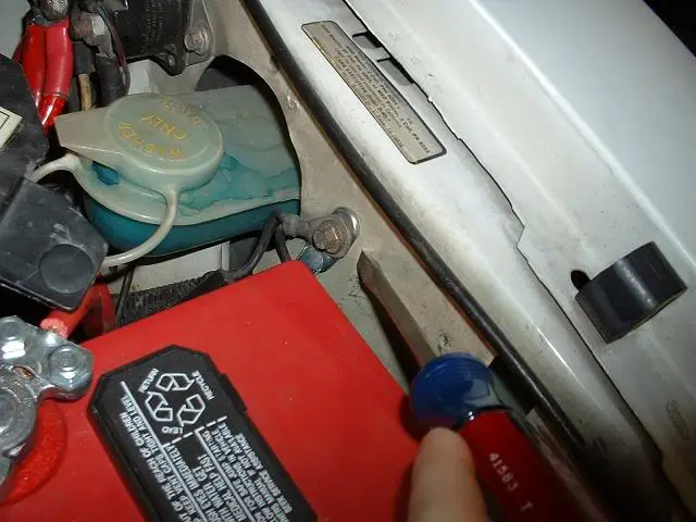
Correct negative battery ground cable.

3.) The computer's main power ground (the one that comes from the battery ground wire) uses pins 40 & 60 for all the things it controls internally: it comes off the ground pigtail on the battery ground wire. Due to its proximity to the battery, it may become corroded by acid fumes from the battery.
In 86-90 model cars, it is a black cylinder about 2 1/2" long by 1" diameter with a black/lt green wire.
In 91-95 model cars it is a black cylinder about 2 1/2" long by 1" diameter with a black/white wire.
You'll find it up next to the starter solenoid where the wire goes into the wiring harness.
All the grounds listed in items 1,2 & 3 need to bolt to clean, shiny bare metal. A wire brush or some fine sandpaper is the best thing to use to clean the ground connections.
4.) All the sensors have a common separate signal ground. This includes the TPS, ACT, EGR, BAP, & VSS sensors. This ground is inside the computer and connects pin 46 to pins 40 & 60, which are the main computer grounds. If this internal computer ground gets damaged, you won't be able to dump codes and the car will have idle/stall/ performance problems
5.) The O2 sensor heaters have their own ground (HEGO ground) coming from the computer. This is different and separate from the O2 sensor ground. It is an orange wire with a ring terminal on it. It is located in the fuel injector wiring harness and comes out under the throttle body. It gets connected to a manifold or bolt on back of the cylinder head.
6.) The TFI module has 2 grounds: one for the foil shield around the wires and another for the module itself. The TFI module ground terminates inside the computer.
7.) The computer takes the shield ground for the TFI module and runs it from pin 20 to the chassis near the computer.
8.) Fuel pump ground the fuel pump has a ground pigtail the connects to the body under the gas tank. You have to drop the gas tank to see where it bolts to the body.
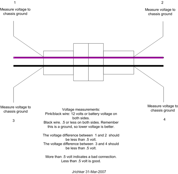
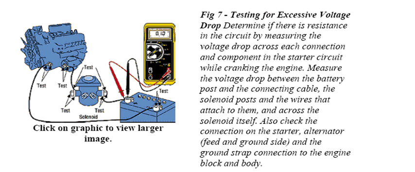
See http://assets.fluke.com/appnotes/automotive/beatbook.pdf for help troubleshooting voltage drops across connections and components. Be sure to have the maximum load on a circuit when testing voltage drops across connections. As current across a defective or weak connection, increases so does the voltage drop. A circuit or connection may check out good with no load or minimal load, but show up bad under maximum load conditions. .
Voltage drops should not exceed the following:
200 mV Wire or cable
300 mV Switch
100 mV Ground
0 mV to <50 mV Sensor Connections
0.0V bolt together connections
]
Extra grounds are like the reserve parachute for a sky diver. If the main one fails, there is always your reserve.
The best plan is to have all the grounds meet at one central spot and connect together there. That eliminates any voltage drops from grounds connected at different places. A voltage drop between the computer ground and the alternator power ground will effectively reduce the voltage available to the computer by the amount of the drop.
This checklist applies to all Mustangs , not just the EFI equipped cars. Some of the wiring will be different on carb cars and carb conversions
Revised 26 –Oct -2016 to add fuel pump ground to the list.
Grounds are important to any electrical system, and especially to computer controlled engines. In an automobile, the ground is the return path for power to get back to the alternator and battery.
Make sure that all the ground places are clean and shiny bare metal: no paint, no corrosion.
1.) The main power ground is from engine block down by the oil filter to battery: it is the power ground for the starter & alternator.
2.) The secondary power ground is between the back of the intake manifold and the driver's side firewall. It is often missing or loose. It supplies ground for the alternator, A/C compressor clutch and other electrical accessories such as the gauges. The clue to a bad ground here is that the temp gauge goes up as you add electrical load such as heater, lights and A/C.
Any car that has a 3G or high output current alternator needs a 4 gauge ground wire running from the block to the chassis ground where the battery pigtail ground connects. The 3G has a 130 amp capacity, so you wire the power side with 4 gauge wire. It stands to reason that the ground side handles just as much current, so it needs to be 4 gauge too.
The picture shows the common ground point for the battery , computer, & extra 3G alternator ground wire as described above in paragraph 2. A screwdriver points to the bolt that is the common ground point.
The battery common ground is a 10 gauge pigtail with the computer ground attached to it.
Picture courtesy timewarped1972
Correct negative battery ground cable.
3.) The computer's main power ground (the one that comes from the battery ground wire) uses pins 40 & 60 for all the things it controls internally: it comes off the ground pigtail on the battery ground wire. Due to its proximity to the battery, it may become corroded by acid fumes from the battery.
In 86-90 model cars, it is a black cylinder about 2 1/2" long by 1" diameter with a black/lt green wire.
In 91-95 model cars it is a black cylinder about 2 1/2" long by 1" diameter with a black/white wire.
You'll find it up next to the starter solenoid where the wire goes into the wiring harness.
All the grounds listed in items 1,2 & 3 need to bolt to clean, shiny bare metal. A wire brush or some fine sandpaper is the best thing to use to clean the ground connections.
4.) All the sensors have a common separate signal ground. This includes the TPS, ACT, EGR, BAP, & VSS sensors. This ground is inside the computer and connects pin 46 to pins 40 & 60, which are the main computer grounds. If this internal computer ground gets damaged, you won't be able to dump codes and the car will have idle/stall/ performance problems
5.) The O2 sensor heaters have their own ground (HEGO ground) coming from the computer. This is different and separate from the O2 sensor ground. It is an orange wire with a ring terminal on it. It is located in the fuel injector wiring harness and comes out under the throttle body. It gets connected to a manifold or bolt on back of the cylinder head.
6.) The TFI module has 2 grounds: one for the foil shield around the wires and another for the module itself. The TFI module ground terminates inside the computer.
7.) The computer takes the shield ground for the TFI module and runs it from pin 20 to the chassis near the computer.
8.) Fuel pump ground the fuel pump has a ground pigtail the connects to the body under the gas tank. You have to drop the gas tank to see where it bolts to the body.
See http://assets.fluke.com/appnotes/automotive/beatbook.pdf for help troubleshooting voltage drops across connections and components. Be sure to have the maximum load on a circuit when testing voltage drops across connections. As current across a defective or weak connection, increases so does the voltage drop. A circuit or connection may check out good with no load or minimal load, but show up bad under maximum load conditions. .
Voltage drops should not exceed the following:
200 mV Wire or cable
300 mV Switch
100 mV Ground
0 mV to <50 mV Sensor Connections
0.0V bolt together connections
]
Extra grounds are like the reserve parachute for a sky diver. If the main one fails, there is always your reserve.
The best plan is to have all the grounds meet at one central spot and connect together there. That eliminates any voltage drops from grounds connected at different places. A voltage drop between the computer ground and the alternator power ground will effectively reduce the voltage available to the computer by the amount of the drop.


Make sure that all the ground places are clean and shiny bare metal: no paint, no corrosion.
1.) The main power ground is from engine block down by the oil filter to battery: it is the power ground for the starter & alternator.
Ok so I've always wanted to know this. How do you only attach to bare shiny steel when a week after it will be rusted?
Also, do you have a picture of this #1 ground? It's always stated "to engine block" when it's actually factory located on the timing cover.
The factory battery ground is bolted to the timing cover, next to the oil pressure sender, the ground on the drivers side firewall in grounded to the back of the head.
bolting the ground wires to aluminum like intake/brackets may or may not cause problems right away, electrolysis will happen making the connections poor. Think of it like adding butt connectors in line on a wire, each connector will have resistance and voltage drop is inevitable.
spray a little paint on the connection and it will not rust.
done right once and fogetaboutit.
bolting the ground wires to aluminum like intake/brackets may or may not cause problems right away, electrolysis will happen making the connections poor. Think of it like adding butt connectors in line on a wire, each connector will have resistance and voltage drop is inevitable.
spray a little paint on the connection and it will not rust.
done right once and fogetaboutit.
Last edited:
Boostedpimp
20+ Year Stangneter
Ok so I've always wanted to know this. How do you only attach to bare shiny steel when a week after it will be rusted?
a lite coat of dielectric grease
Here's where I attached it, pretty much right where it shows, but it went into the timing cover and not the block itself. Now the cover is attached to the block, but i'm not certain how conductive aluminum is compared to the Iron block, or if there is some bolt hole I missed.

I was curious so I went out and looked at mine and yes it is bolted to the timing cover. No mistake, my car is as close to factory with only a couple mods. There is also a bracket that holds a wire harness in the same place.
I've looked for a pic and ran across this. It's one of the few I could find and just so happened to be on here and was a thread specifically about that very ground location. I do not see any place on the block in that area to put a ground and like you said Thief, your car is close to factory and has the bracket just like mine also bolted to the only place on that side....the timing cover. This particular ground location has been driving me nuts. I've wanted to make sure the factory grounds are in the correct spot and that one is where mine was when I bought the car new. Always been the timing cover. Every time the long ground thread is posted it's emphatically said that that ground should not go to the timing cover. Seems both of our cars contradict that. Could we please for the sake of new people who are trying to learn and old people that are worrying too much (that'd be ME) please fix that in the long post and not say it's wrong to be in that factory location?? My only goal is to get all the little stuff on my car correct...nothing rude meant at all.
The only other decent pic I could find......the only hole there is for the sending unit extension. There is no other place that I see?
BUSTED! You are absolutely right. The ground bolt is right next to the oil sending unit extension and IS in the timing cover! I confirmed it on my car, don't know why I keep thinking it is on the block.
this is likely why I have the idiot light. I
i have corrected my statements in the above post.
Thanks, I'll take my punishment now.
this is likely why I have the idiot light. I
i have corrected my statements in the above post.
Thanks, I'll take my punishment now.
Last edited:
lol....no punishment. I'm just happy I don't have to move mine because I trust ya'll and would if I shouldBUSTED! You are absolutely right. The ground bolt is right next to the oil sending unit extension and IS in the timing cover! I confirmed it on my car, don't know why I keep thinking it is on the block.
this is likely why I have the idiot light. I
i have corrected my statements in the above post.
Thanks, I'll take my punishment now.

Thanks for checking on it!!
I realize this is a way old post, but on #2 the ground that goes form the intake to the firewall- where on the firewall is is supposed to attach from the factory?Grounds
This checklist applies to all Mustangs , not just the EFI equipped cars. Some of the wiring will be different on carb cars and carb conversions
Revised 26 –Oct -2016 to add fuel pump ground to the list.
Grounds are important to any electrical system, and especially to computer controlled engines. In an automobile, the ground is the return path for power to get back to the alternator and battery.
Make sure that all the ground places are clean and shiny bare metal: no paint, no corrosion.
1.) The main power ground is from engine block down by the oil filter to battery: it is the power ground for the starter & alternator.
2.) The secondary power ground is between the back of the intake manifold and the driver's side firewall. It is often missing or loose. It supplies ground for the alternator, A/C compressor clutch and other electrical accessories such as the gauges. The clue to a bad ground here is that the temp gauge goes up as you add electrical load such as heater, lights and A/C.
Any car that has a 3G or high output current alternator needs a 4 gauge ground wire running from the block to the chassis ground where the battery pigtail ground connects. The 3G has a 130 amp capacity, so you wire the power side with 4 gauge wire. It stands to reason that the ground side handles just as much current, so it needs to be 4 gauge too.
The picture shows the common ground point for the battery , computer, & extra 3G alternator ground wire as described above in paragraph 2. A screwdriver points to the bolt that is the common ground point.
The battery common ground is a 10 gauge pigtail with the computer ground attached to it.
Picture courtesy timewarped1972
Correct negative battery ground cable.
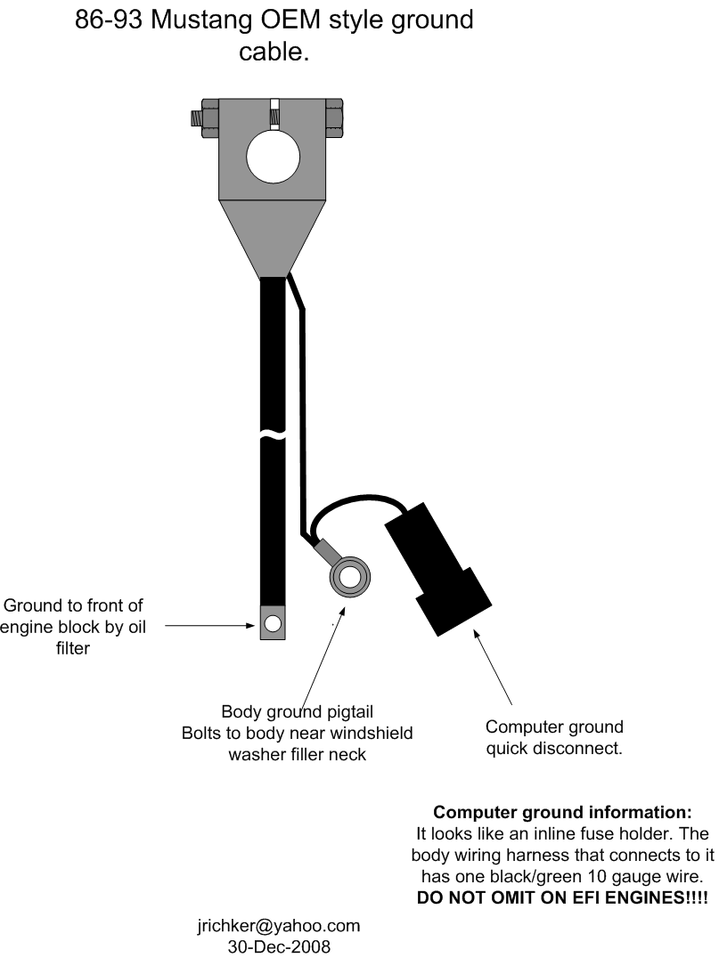
3.) The computer's main power ground (the one that comes from the battery ground wire) uses pins 40 & 60 for all the things it controls internally: it comes off the ground pigtail on the battery ground wire. Due to its proximity to the battery, it may become corroded by acid fumes from the battery.
In 86-90 model cars, it is a black cylinder about 2 1/2" long by 1" diameter with a black/lt green wire.
In 91-95 model cars it is a black cylinder about 2 1/2" long by 1" diameter with a black/white wire.
You'll find it up next to the starter solenoid where the wire goes into the wiring harness.
All the grounds listed in items 1,2 & 3 need to bolt to clean, shiny bare metal. A wire brush or some fine sandpaper is the best thing to use to clean the ground connections.
4.) All the sensors have a common separate signal ground. This includes the TPS, ACT, EGR, BAP, & VSS sensors. This ground is inside the computer and connects pin 46 to pins 40 & 60, which are the main computer grounds. If this internal computer ground gets damaged, you won't be able to dump codes and the car will have idle/stall/ performance problems
5.) The O2 sensor heaters have their own ground (HEGO ground) coming from the computer. This is different and separate from the O2 sensor ground. It is an orange wire with a ring terminal on it. It is located in the fuel injector wiring harness and comes out under the throttle body. It gets connected to a manifold or bolt on back of the cylinder head.
6.) The TFI module has 2 grounds: one for the foil shield around the wires and another for the module itself. The TFI module ground terminates inside the computer.
7.) The computer takes the shield ground for the TFI module and runs it from pin 20 to the chassis near the computer.
8.) Fuel pump ground the fuel pump has a ground pigtail the connects to the body under the gas tank. You have to drop the gas tank to see where it bolts to the body.
See http://assets.fluke.com/appnotes/automotive/beatbook.pdf for help troubleshooting voltage drops across connections and components. Be sure to have the maximum load on a circuit when testing voltage drops across connections. As current across a defective or weak connection, increases so does the voltage drop. A circuit or connection may check out good with no load or minimal load, but show up bad under maximum load conditions. .
Voltage drops should not exceed the following:
200 mV Wire or cable
300 mV Switch
100 mV Ground
0 mV to <50 mV Sensor Connections
0.0V bolt together connections
]
Extra grounds are like the reserve parachute for a sky diver. If the main one fails, there is always your reserve.
The best plan is to have all the grounds meet at one central spot and connect together there. That eliminates any voltage drops from grounds connected at different places. A voltage drop between the computer ground and the alternator power ground will effectively reduce the voltage available to the computer by the amount of the drop.
The ground you are referring to bolts from the back of the drivers side head to the firewall, the firewall location will be in the area under where the accelerator cable comes through the firewall.

79 Fox
Active Member
I have both my stock ground position with the stock ground wire and an aftermarket one from the starter motor to the body.
Similar threads
- Replies
- 0
- Views
- 119

- Replies
- 0
- Views
- 248
- Replies
- 0
- Views
- 402

- Replies
- 5
- Views
- 172

