
Although if you're going to push it in to check for fuel, have someone get a video of it.
Just in case.
Just in case.
Fuel Pump Troubleshooting for 87-90 MustangsI did, a little came out like a small squirt, I replaced my fuel filter and a good stream would come out maybe 2 or 3 seconds Atleast but a few days later I check the fuel pressure again and it’s just a small squirt.
Fuel Pump Troubleshooting for 87-90 Mustangs
Revised 1-Dec-2015 to add fuse links diagram.
Clue – listen for the fuel pump to prime when you first turn the ignition switch on. It should run for 1-3 seconds and shut off. To trick the fuel pump into running, find the ECC test connector and jump the connector in the upper LH corner to ground.
Foxbody Diagnostic connector

Foxbody Diagnostic connector close up view

Turn the ignition switch on when you do this test.
If the fuse links are OK, you will have power to the pump. Check fuel pressure – remove the cap from the Schrader valve behind the alternator and depress the core. Fuel should squirt out, catch it in a rag. A tire pressure gauge can also be used if you have one - look for 37-40 PSI. Beware of fire hazard when you do this.
No fuel pressure, possible failed items in order of their probability:
A.) Tripped inertia switch – press reset button on the inertia switch. The hatch cars hide it under the plastic trim covering the driver's side taillight. Use the voltmeter or test light to make sure you have power to both sides of the switch
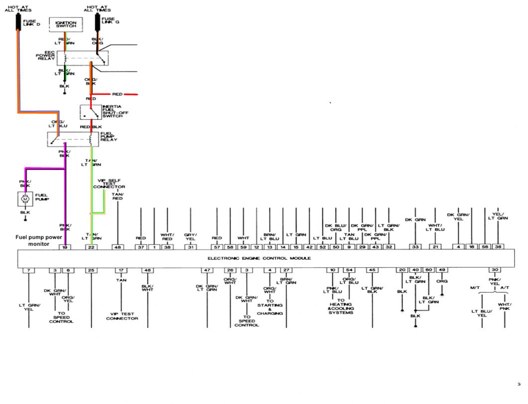
B.) Fuel pump power relay – located under the driver’s seat in most Mustangs built before 92. See the diagram to help identify the fuel pump relay wiring colors. Be sure to closely check the condition of the relay, wiring & socket for corrosion and damage.
C.) Clogged fuel filter
D.) Failed fuel pump
E.) Blown fuse link in wiring harness.
F.) Fuel pressure regulator failed. Remove vacuum line from regulator and inspect for fuel escaping while pump is running.

The electrical circuit for the fuel pump has two paths, a control path and a power path.
Control Path
The control path consists of the inertia switch, the computer, and the fuel pump relay coil. It turns the fuel pump relay on or off under computer control. The switched power (red wire) from the ECC relay goes to the inertia switch (red/black wire) then from the inertia switch to the relay coil and then from the relay coil to the computer (tan/ Lt green wire). The computer provides the ground path to complete the circuit. This ground causes the relay coil to energize and close the contacts for the power path. Keep in mind that you can have voltage to all the right places, but the computer must provide a ground. If there is no ground, the relay will not close the power contacts.
Power Path
The power path picks up from a fuse link near the starter relay. Fuse links are like fuses, except they are pieces of wire and are made right into the wiring harness. The feed wire from the fuse link (orange/ light blue wire) goes to the fuel pump relay contacts. The fuse links are in a bundle up near the starter relay; you will have to unwrap the wiring harness to find them.
Fuse links

Fuse links come with a current rating just like fuses. A clue as to what current they are designed for is to look at the size wire they protect. Fuse link material is available at most good auto parts stores. There may even be a fuse link already made up specifically for your car. Just be sure to solder the connection and cover it with heat shrink tubing.
Heat shrink tubing is available at Radio Shack or other electronics supply stores.
See the video below for help on soldering and heat shrinking wiring. There is a lot of useful help and hints if you don’t do automotive electrical work all the time.
View: http://youtu.be/uaYdCRjDr4A
When the contacts close because the relay energizes, the power flows through the contacts to the fuel pump (light pink/black wire). Notice that pin 19 on the computer is the monitor to make sure the pump has power. The fuel pump has a black wire that supplies the ground to complete the circuit.
Remember that the computer does not source any power to actuators, relays or injectors, but provides the ground necessary to complete the circuit. That means one side of the circuit will always be hot, and the other side will go to ground or below 1 volt as the computer switches on that circuit.
Now that you have the theory of how it works, it’s time to go digging.
All voltage reading are made with one voltmeter lead connected to the metal car body unless otherwise specified
Check for 12 volts at the red wire on the inertia switch. No 12 volts at the inertia switch, the ignition switch is turned off or faulty or there is no power to the EEC (computer) power relay. To be sure look for good 12 volts on the red wire on any fuel injector.
Good 12 volts means the EEC relay is working. No 12 volts and the ECC wiring is at fault.
Look for 12 volts on the red/green wire on the ignition coil: no 12 volts and the ignition switch is faulty, or the fuse link in the ignition power wire has blown. No 12 volts here and the ECC relay won’t close and provide power to the inertia switch. Check the Red/black wire on the inertia switch, it should have 12 volts. No 12 volts there, either the inertia switch is open or has no power to it. Check both sides of the inertia switch: there should be power on the Red wire and Red/Black wire. Power on the Red wire and not on the Red/Black wire means the inertia switch is open. Push the button on the side of it to reset it, and then recheck. Good 12 volts on one side and not on the other means the inertia switch has failed.
Look for 12 volts at the Orange/Lt. Blue wire (power source for fuel pump relay). No voltage or low voltage, bad fuse link, bad wiring, bad ignition switch or ignition switch wiring or connections. There is a mystery connector somewhere under the driver’s side kick panel, between the fuel pump relay and the fuse link.
Turn on the key and jumper the fuel pump test connector to ground as previously described. Look for 12 volts at the Light Pink/Black wire (relay controlled power for the fuel pump). No voltage there means that the relay has failed, or there is a broken wire in the relay control circuit.
Pump wiring: Anytime the ignition switch is in the Run position and the test point is jumpered to ground, there should be at least 12 volts present on the black/pink wire. With power off, check the pump ground: you should see less than 1 ohm between the black wire and chassis ground.

The yellow wire is the fuel tank sender to the fuel quantity gage. The two black wires are grounds. One ground is for the fuel tank sender and the other is the fuel pump. The ground for the fuel pump may be larger gauge wire that the fuel tank sender ground wire.
Make sure that the power is off the circuit before making any resistance checks. If the circuit is powered up, your resistance measurements will be inaccurate.
You should see less than 1 Ohm between the black wire(s) and ground. To get some idea of what a good reading is, short the two meter leads together and observe the reading. It should only be slightly higher when you measure the black wire to ground resistance.
The Tan/Lt Green wire provides a ground path for the relay power. With the test connector jumpered to ground, there should be less than .75 volts. Use a test lamp with one side connected to battery power and the other side to the Tan/Lt Green wire. The test light should glow brightly. No glow and you have a broken wire or bad connection between the test connector and the relay. To test the wiring from the computer, remove the passenger side kick panel and disconnect the computer connector. It has a 10 MM bolt that holds it in place. With the test lamp connected to power, jumper pin 22 to ground and the test lamp should glow. No glow and the wiring between the computer and the fuel pump relay is bad.
Computer: If you got this far and everything else checked out good, the computer is suspect. Remove the test jumper from the ECC test connector located under the hood. Probe computer pin 22 with a safety pin and ground it to chassis. Make sure the computer and everything else is connected. Turn the ignition switch to the Run position and observe the fuel pressure. The pump should run at full pressure.
If it doesn't, the wiring between pin 22 on the computer and the fuel pump relay is bad.
If it does run at full pressure, the computer may have failed.
Keep in mind that the computer only runs the fuel pump for about 2-3 seconds when you turn the key to the Run position. This can sometimes fool you into thinking the computer has died. Connect one lead of the test light to power and the other lead to computer pin 22 with a safety pin. With the ignition switch Off, jumper the computer into self test mode like you are going to dump the codes. Turn the ignition switch to the Run position. The light will flicker when the computer does the self test routine. A flickering light is a good computer. No flickering light is a bad computer.
Remove the test jumper from the ECC test connector located under the hood.
Fuel pump runs continuously: The fuel pump relay contacts are stuck together or the Tan/Lt Green wire has shorted to ground. In extreme ghetto cases, the pump relay may have been bypassed. Remove the fuel pump relay from its socket. Then disconnect the computer and use an ohmmeter to check out the resistance between the Tan/Lt Green wire and ground. You should see more than 10 K Ohms (10,000 ohms) or an infinite open circuit. Be sure that the test connector isn’t jumpered to ground.
If the wiring checks out good, then the computer is the likely culprit.

Prior to replacing the computer, check the computer power ground. The computer has its own dedicated power ground that comes off the ground pigtail on the battery ground wire. Due to it's proximity to the battery, it may become corroded by acid fumes from the battery. It is a black cylinder about 2 1/2" long by 1" diameter with a black/lt green wire. You'll find it up next to the starter solenoid where the wire goes into the wiring harness
If all of the checks have worked OK to this point, then the computer is bad. The computers are very reliable and not prone to failure unless there has been significant electrical trauma to the car. Things like lightning strikes and putting the battery in backwards or connecting jumper cables backwards are about the only thing that kills the computer.
See the following website for some help from Tmoss (diagram designer) &
Stang&2Birds (website host)
http://www.veryuseful.com/mustang/tech/engine/images/IgnitionSwitchWiring.gif
http://www.veryuseful.com/mustang/tech/engine/images/fuel-alt-links-ign-ac.gif
http://www.veryuseful.com/mustang/tech/engine/images/88-91eecPinout.gif
Fuel pump replacement 5.0 Fox body Mustangs
Here are some useful tips...
I have done the tank removal three times, and the main issues are getting the car up on jack stands and getting the gas out of the tank. DO NOT try to do this job without jack stands. Becoming a pancake is not part of the repair process.
Pumping out the old gas:
If the old pump still works, you can use it to pump the tank out.
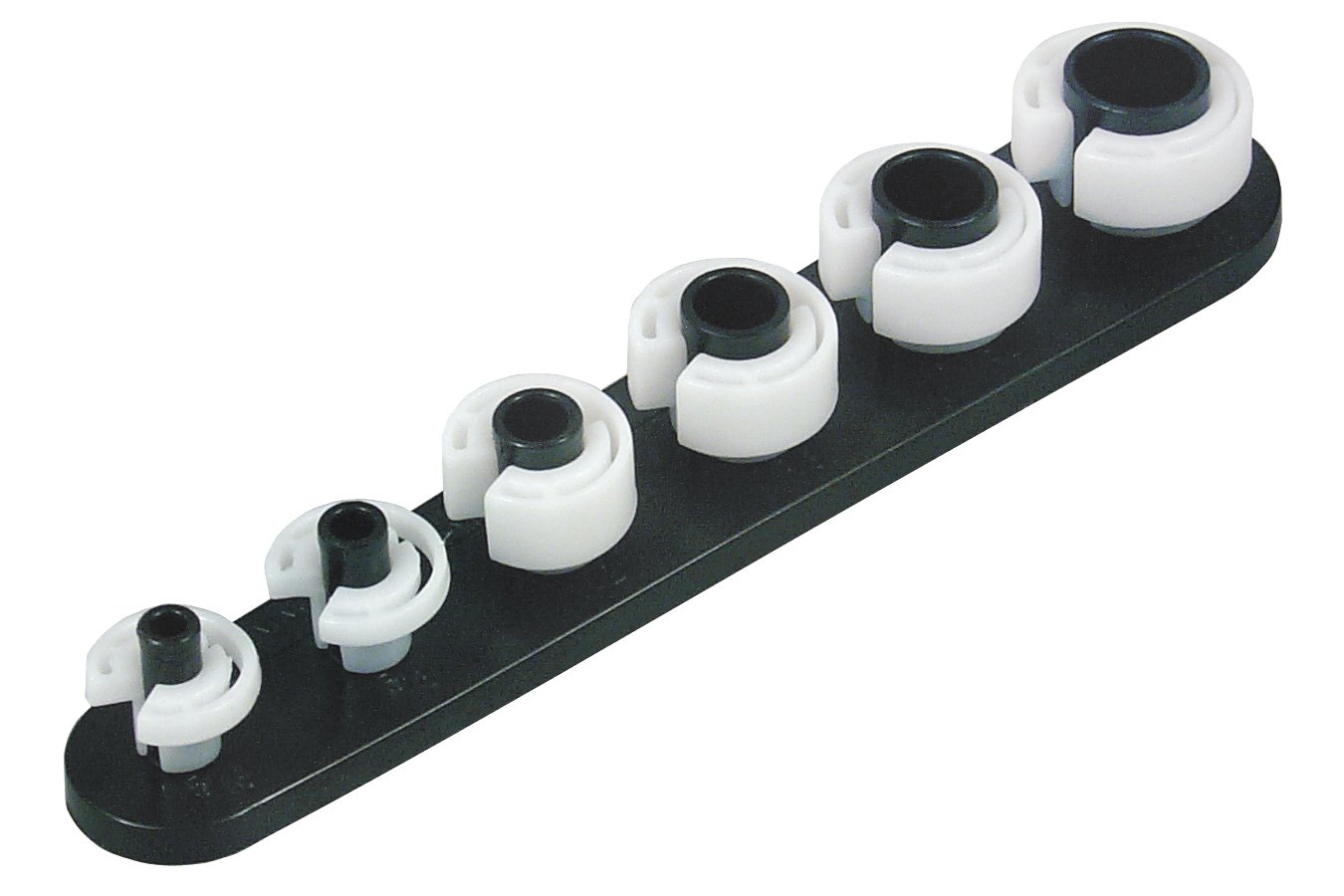
1.) Separate the pressure line (the one with the Schrader valve on it) using the fuel line tools.
Look in the A/C repair section for the fuel line tools. They look like little plastic top hats. You will need the 1/2" & 5/8" ones. The hat shaped section goes on facing the large part of the coupling. Then you press hard on the brim until it forces the sleeve into the coupling and releases the spring. You may need someone to pull on the line while you press on the coupling.

OR

View: https://www.youtube.com/watch?v=vRTjYAxvaCs
Use a piece of garden hose to run from the pressure line to your bucket or gas can. Make sure it is as leak proof as you can make it. Fire and explosion are not part of the repair process...
2.) Jumper the fuel pump test point to ground.
Turn the ignition switch to the Run position. the fuel pump will pump the tank almost dry unless the battery runs down first.
Some 5 gallon paint pails lined with garbage bags are good to hold the gas. The garbage bags provide a clean liner for the pails and keep the loose trash out of the gas so you can reuse it. If you decide to use a siphon, a piece of 1/2" garden hose stuck down the filler neck will siphon all but a gallon or so of the gas.
Remove the filler neck bolts and put them in a zip bag. Disconnect the supply & return lines by removing the plastic clips from the metal tubing. If you damage the clips, you can get new ones form the auto part store for just a few dollars. I have used tie-wraps, but that is not the best choice. Then you remove the two 9/16" nuts that hold the T bolts to the straps. Put the nuts in the zip bag with the filler bolts. Pull the plastic shield down and away from the tank. Once the tank drops a little bit you can disconnect the wiring for the pump & fuel quantity sender.
The pump assembly comes out by removing a large metal ring that unscrews from the tank. You are supposed to use a brass punch to tap on the ring so that you don't make sparks. Look closely at the rubber O ring gasket when you remove the sender: it is very easy to damage on reinstallation. If it gets damaged, the car will smell like gasoline when you fill the tank up. The pump assembly requires some twisting and turning to get it out the hole.
Look very closely at the electrical wiring. The stock fuel pump wiring can overheat and melt the insulation. Mine had some really crummy plastic tubing slid over the quick disconnects. If the wires ever got together, there would be sparks inside the fuel tank and no more Mustang. I eliminated the splice in the middle of the wiring and went straight from the pump to the feed through connectors for the wiring. It required some soldering and crimping of new tabs on the wires, but it made a neater job.
Inspect the pump mount to metal tubing bracket. Mine broke and I couldn't get it to solder back together. I drilled a small hole for a machine screw & self locking nut to hold the clamp and bracket together.
The pump is easy to get off the mount but is somewhat difficult to get back it the tank without damaging the sock filter or tearing it on the tank baffle. When you install the metal ring that holds the pump in place, watch out for the gasket O ring. Some RTV may be helpful if the ring is not in excellent condition.
The tank to filler pipe seal is a large rubber grommet. Inspect it for hardening, tears and damage. At $20 from the Ford dealer, it might be a good idea to replace it.
I used a floor jack to help lift the tank back in place. A piece of ¾” plywood cut to about the same size as the tank will help insure that you don’t damage the tank by using the floor jack to lift it in place. You may find that it is the only time you really can make good use of a helper.
It’s Decision Tree time:Thank you sir will Check that out. But starter fluid doesn’t start my car even for a second and I have a little fuel pressure. Not sure an exact amount. I have spark but it’s weaker than my friends spark who also has an 89 Fox. Not sure what it could be. Tested it with a screwdriver and a ignition plug
