
Hey guys, I’m having trouble with my 92 5.0 lx. My current problem is my car will start and run for about 30 seconds to a minute and then will stall out. Starts right back up but keeps doing the same thing over and over again. My first problem with the car started back in the summer. The fuel pump would constantly run without shutting off when the key was turned on and the car wouldn’t not start at all, it randomly died on me one morning coming home from work and I had to tow it home. After changing the tfi, distributor, cap and rotor, fuel pressure regulator, and a few injectors as a precaution it still didn’t work. I ended up changing the computer with one from a 90 I got off of eBay and it fixed the problem. The car ran ok for about a month but would buck/jerk at high way speeds. I ended up changing the iac valve, and cleaned the throttle body and mass air sensor with the appropriate cleaners and even changed the tps sensor and calibrated it to the right voltage. The car will now fire up and idle and rev just fine, but it will not run for longer than a minute. So I thought it was maybe the fuel pump going bad (keep in mind the car sat and I haven’t worked on it since September). Bought a brand new walbro 255lph and put it in on Sunday and still the same problem. Before the fuel pump change the car would die and not start unless you cycled the key on and off a few times and then it would start back up just to keep doing the same thing. It now fires rift back up every time but keeps dying. I’m stumped! Could this computer be bad too? It’s like somebody is pulling the plug on the power and or fuel it’ll stumble and you can hear it start to cut out and then it dies. Hear the fuel pump and the eec(or ecc relay, whatever it’s called clicking) and that’s it. I don’t really hear the fuel pump runnig while the car is running like I used to before I started having problems after it initially primes now. Kinda leaning towards the computer again? Seems like something electrical/fuel related. Before I changed the fuel pump I was getting codes 81,10, and 11 when the car was cold. After letting it run and stall out it would throw 81,10, and 87. Anybody ever have this kind of problem or have an idea what it is because this has me stumped. Was thinking about sending my original computer sent out to get rebuilt but I’m not sure if that’s the problem. Car is a 92 5.0 lx auto that I have owned for 8 years and was completely stock and all original when I got it. Thanks in advance for any and all help!
You are using an out of date browser. It may not display this or other websites correctly.
You should upgrade or use an alternative browser.
You should upgrade or use an alternative browser.
Fuel 92 5.0 fox won’t stay running
- Thread starter Stonerboys
- Start date
Code 87 – fuel pump primary circuit failure. The fuel pump lost power while the engine was running. Check fuel pump relay, check inertia switch, wiring to/from inertia switch, red wire going to inertia switch for +12volts. Check the other side of inertia switch for +12 volts.
Fuel Pump Troubleshooting for 91-93 Mustangs
Revised 6-Feb-2016 to add fuse link diagram
Ignition switch in the Run position, engine not running tests.
Clue – listen for the fuel pump to prime when you first turn the ignition switch on.
It should run for 2-5 seconds and shut off. To trick the fuel pump into running, find the ECC test connector and jump the connector in the upper RH corner to ground.
Foxbody Diagnostic connector
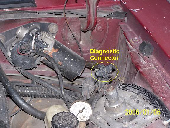
Foxbody Diagnostic connector close up view

If the fuse links are OK, you will have power to the pump. Check fuel pressure – remove the cap from the Schrader valve behind the alternator and depress the core. Fuel should squirt out, catch it in a rag. A tire pressure gauge can also be used if you have one - look for 37-40 PSI. Beware of fire hazard when you do this.
No fuel pressure, possible failed items in order of their probability:
A.) Tripped inertia switch – press reset button on the inertia switch. The hatch cars hide it under the plastic trim covering the driver's side taillight. Use the voltmeter or test light to make sure you have power to both sides of the switch
B.) Fuel pump Relay:
On 91 cars, it is located under the driver's seat.
On 92 and 93 cars it is located under the MAF. Be careful not to confuse it with the A/C WOT cutoff relay which is in the same area. See the diagram to help identify the fuel pump relay wiring colors.
Be sure to closely check the condition of the relay, wiring & socket for corrosion and damage.
C.) Clogged fuel filter
D.) Failed fuel pump
E.) Blown fuse link in wiring harness.
F.) Fuel pressure regulator failed. Remove vacuum line from regulator and inspect
for fuel escaping while pump is running.
Theory of operation:
Read this section through several times. If you understand the theory of operation, this will be much easier to troubleshoot. Refer to the diagram below frequently.
Diagram of the fuel pump wiring for 91-93 cars.
The electrical circuit for the fuel pump has two paths, a control path and a power
path.
Remember that the computer does not source any power to actuators, relays or injectors, but provides the ground necessary to complete the circuit. That means one side of the circuit will always be hot, and the other side will go to ground or below 1 volt as the computer switches on that circuit.
Control Path
The control path consists of the computer, and the fuel pump relay coil. It turns the fuel pump relay on or off under computer control. The switched power (red wire) from the ECC relay goes to the relay coil and then from the relay coil to the computer (light blue\orange wire). The computer provides the ground path to complete the circuit. This ground causes the relay coil to energize and close the contacts for the power path. Keep in mind that you can have voltage to all the right places, but the computer must provide a ground. If there is no ground, the relay will not close the power contacts.
Computer power path
The computer power relay must properly function to provide power for the fuel pump relay. That means you must check the operation of the computer power relay (PCM Power Relay) before chasing any problems with the fuel pump circuit. The computer power relay is located above the computer under the passenger side kick plate cover. . It is not easy to get to, you must have small hands or pull the passenger side dash speaker out to access it.
With the Ignition switch in the Off position, check the resistance between the black/white wire and a clean bare spot on the car body metal. You should see less that 1 Ohm. More than 1 Ohm is a broken wire, or bad connection of the black/white wire and the car body metal.
Check for 12 volts at the yellow wire. Good 12 volts and the fuse link is OK. No voltage or low voltage, bad fuse link, bad wiring, or connections.
With the Ignition switch in the Run position, look for good 12 volts on the red/green wire. No voltage or low voltage, bad fuse link, bad wiring, or connections.
Good 12 volts on the red/green wire, look for good 12 volts on the red wire or any of the red fuel injector wires. No 12 volts or low voltage and the relay isn’t closing, or relay socket contacts are dirty/corroded. Water has been known to run down the radio antenna wire or leak from the windshield and get into the relay and relay contacts.
Fuel pump power path
The power path picks up from a fuse link near the starter relay. Fuse links are like fuses, except they are pieces of wire and are made right into the wiring harness. The feed wire from the fuse link (pink/black wire) goes to the fuel pump relay contacts. When the contacts close because the relay energizes, the power flows through the pink/black wire to the contacts and through the dark green\yellow wire to the inertia switch. The other side of the inertia switch with the brown\pink wire joins the pink/black wire that connects to the fuel pump. The fuel pump has a black wire that supplies the ground to complete the circuit.
Fuse links at starter solenoid

Fuse links come with a current rating just like fuses. A clue as to what current they are designed for is to look at the size wire they protect.
Fuse link material is available at most good auto parts stores. There may even be a fuse link already made up specifically for your car. Just be sure to solder the connection and cover it with heat shrink tubing.
Heat shrink tubing is available at Radio Shack or other electronics supply stores.
See the video below for help on soldering and heat shrinking wiring. There is a lot of useful help and hints if you don’t do automotive electrical work all the time.
View: http://youtu.be/uaYdCRjDr4A
Power feed: Look for 12 volts at the pink/black wire (power source for fuel pump relay).
No voltage or low voltage, bad fuse link, bad wiring, or connections. Remember that on 92 or later models the fuel pump relay is located under the Mass Air meter. Watch out for the WOT A/C control relay on these cars, as it is located in the same place and can easily be mistaken for the fuel pump relay.
Relay: Turn on the key and jumper the ECC test connector as previously described. Look for 12 volts at the dark green\yellow wire (relay controlled power for the fuel pump). No voltage there means that the relay has failed, or there is a broken wire in the relay control circuit.
Inertia switch:
The location for the inertia switch is under the plastic for the driver's side taillight.
There should be a round plastic pop out cover over it, remove it to access the switch button.
With the test connection jumpered and ignition switch in The Run position as described above, check the brown/pink wire. It should have 12 volts. No 12 volts there, either the inertia switch is open or has no power to it. Check both sides of the inertia switch: there should be power on the dark green\yellow (inertia switch input) and brown/pink wire (inertia switch output). Power on the dark green\yellow wire and not on the brown/pink wire means the inertia switch is open.
Press on the red plunger to reset it to the closed position. Sometimes the inertia switch will be intermittent or will not pass full power. Be sure that there is 12 volts on both sides of the switch with the pump running and that the voltage drop measured across the switch is less than .75 volts.
Pump wiring: Anytime the ignition switch is in the Run position and the test point is jumpered to ground, there should be at least 12 volts present on the black/pink wire. With power off, check the pump ground: you should see less than 1 ohm between the black wire and chassis ground.
Make sure that the power is off the circuit before making any resistance checks.
If the circuit is powered up, your resistance measurements will be inaccurate.
Control path:
Relay: The light blue/orange wire provides a ground path for the relay power. With the test connector jumpered according to the previous instructions, there should be less than .75 volts.
Use a test lamp with one side connected to battery power and the other side to the light blue/orange wire on the fuel pump relay. The test light should glow brightly. No glow and you have a broken wire or bad connection between the test connector and the relay. To test the wiring from the computer, remove the passenger side kick panel and disconnect the computer connector. It has a 10 MM bolt that holds it in place. Remove the test jumper from the ECC test connector.
With the test lamp connected to power, jumper pin 22 to ground and the test lamp should glow.
No glow and the wiring between the computer and the fuel pump relay is bad.
Computer: If you got this far and everything else checked out good, the computer is suspect.
Remove the test jumper from the ECC test connector located under the hood. Probe computer pin 22 with a safety pin and ground it to chassis. Make sure the computer and everything else is connected. Turn the ignition switch to the Run position and observe the fuel pressure. The pump should run at full pressure.
If it doesn't, the wiring between pin 22 on the computer and the fuel pump relay is bad.
If it does run at full pressure, the computer may have failed.
Keep in mind that the computer only runs the fuel pump for about 2-3 seconds when you turn the key to the Run position. This can sometimes fool you into thinking the computer has died.
Connect one lead of the test light to power and the other lead to computer pin 22 with a safety pin.
With the ignition switch Off, jumper the computer into self test mode like you are going to dump the codes. Turn the ignition switch to the Run position. The light will flicker when the computer does the self test routine. A flickering light is a good computer. No flickering light is a bad computer. Remove the test jumper from the ECC test connector located under the hood.
See the following website for some help from Tmoss (diagram designer) & Stang&2Birds (website host)
for help on 88-95 wiring Mustang FAQ - Engine Information
Fuel pump runs continuously:
The fuel pump relay contacts are stuck together or the light blue/orange wire (pin 22) has shorted to ground. Remove the fuel pump relay from its socket. Then disconnect the computer and use an ohmmeter to check out the resistance between the light blue/orange wire and ground. You should see more than 10 K Ohms (10,000 ohms) or an infinite open circuit. Be sure that the test connector isn’t jumpered to ground.
If the wiring checks out good, then the computer is the likely culprit.

Prior to replacing the computer, check the computer power ground. The computer has its own dedicated power ground that comes off the ground pigtail on the battery ground wire. Due to it's proximity to the battery, it may become corroded by acid fumes from the battery. It is a black cylinder about 2 1/2" long by 1" diameter with a black/lt green wire. You'll find it up next to the starter solenoid where the wire goes into the wiring harness.
The picture shows the common ground point for the battery , computer, & extra 3G alternator ground wire as described above. A screwdriver points to the bolt that is the common ground point.
The battery common ground is a 10 gauge pigtail with the computer ground attached to it.
Picture courtesy timewarped1972

Fuel Pump Troubleshooting for 91-93 Mustangs
Revised 6-Feb-2016 to add fuse link diagram
Ignition switch in the Run position, engine not running tests.
Clue – listen for the fuel pump to prime when you first turn the ignition switch on.
It should run for 2-5 seconds and shut off. To trick the fuel pump into running, find the ECC test connector and jump the connector in the upper RH corner to ground.
Foxbody Diagnostic connector
Foxbody Diagnostic connector close up view
If the fuse links are OK, you will have power to the pump. Check fuel pressure – remove the cap from the Schrader valve behind the alternator and depress the core. Fuel should squirt out, catch it in a rag. A tire pressure gauge can also be used if you have one - look for 37-40 PSI. Beware of fire hazard when you do this.
No fuel pressure, possible failed items in order of their probability:
A.) Tripped inertia switch – press reset button on the inertia switch. The hatch cars hide it under the plastic trim covering the driver's side taillight. Use the voltmeter or test light to make sure you have power to both sides of the switch
B.) Fuel pump Relay:
On 91 cars, it is located under the driver's seat.
On 92 and 93 cars it is located under the MAF. Be careful not to confuse it with the A/C WOT cutoff relay which is in the same area. See the diagram to help identify the fuel pump relay wiring colors.
Be sure to closely check the condition of the relay, wiring & socket for corrosion and damage.
C.) Clogged fuel filter
D.) Failed fuel pump
E.) Blown fuse link in wiring harness.
F.) Fuel pressure regulator failed. Remove vacuum line from regulator and inspect
for fuel escaping while pump is running.
Theory of operation:
Read this section through several times. If you understand the theory of operation, this will be much easier to troubleshoot. Refer to the diagram below frequently.
Diagram of the fuel pump wiring for 91-93 cars.
The electrical circuit for the fuel pump has two paths, a control path and a power
path.
Remember that the computer does not source any power to actuators, relays or injectors, but provides the ground necessary to complete the circuit. That means one side of the circuit will always be hot, and the other side will go to ground or below 1 volt as the computer switches on that circuit.
Control Path
The control path consists of the computer, and the fuel pump relay coil. It turns the fuel pump relay on or off under computer control. The switched power (red wire) from the ECC relay goes to the relay coil and then from the relay coil to the computer (light blue\orange wire). The computer provides the ground path to complete the circuit. This ground causes the relay coil to energize and close the contacts for the power path. Keep in mind that you can have voltage to all the right places, but the computer must provide a ground. If there is no ground, the relay will not close the power contacts.
Computer power path
The computer power relay must properly function to provide power for the fuel pump relay. That means you must check the operation of the computer power relay (PCM Power Relay) before chasing any problems with the fuel pump circuit. The computer power relay is located above the computer under the passenger side kick plate cover. . It is not easy to get to, you must have small hands or pull the passenger side dash speaker out to access it.
With the Ignition switch in the Off position, check the resistance between the black/white wire and a clean bare spot on the car body metal. You should see less that 1 Ohm. More than 1 Ohm is a broken wire, or bad connection of the black/white wire and the car body metal.
Check for 12 volts at the yellow wire. Good 12 volts and the fuse link is OK. No voltage or low voltage, bad fuse link, bad wiring, or connections.
With the Ignition switch in the Run position, look for good 12 volts on the red/green wire. No voltage or low voltage, bad fuse link, bad wiring, or connections.
Good 12 volts on the red/green wire, look for good 12 volts on the red wire or any of the red fuel injector wires. No 12 volts or low voltage and the relay isn’t closing, or relay socket contacts are dirty/corroded. Water has been known to run down the radio antenna wire or leak from the windshield and get into the relay and relay contacts.
Fuel pump power path
The power path picks up from a fuse link near the starter relay. Fuse links are like fuses, except they are pieces of wire and are made right into the wiring harness. The feed wire from the fuse link (pink/black wire) goes to the fuel pump relay contacts. When the contacts close because the relay energizes, the power flows through the pink/black wire to the contacts and through the dark green\yellow wire to the inertia switch. The other side of the inertia switch with the brown\pink wire joins the pink/black wire that connects to the fuel pump. The fuel pump has a black wire that supplies the ground to complete the circuit.
Fuse links at starter solenoid
Fuse links come with a current rating just like fuses. A clue as to what current they are designed for is to look at the size wire they protect.
Fuse link material is available at most good auto parts stores. There may even be a fuse link already made up specifically for your car. Just be sure to solder the connection and cover it with heat shrink tubing.
Heat shrink tubing is available at Radio Shack or other electronics supply stores.
See the video below for help on soldering and heat shrinking wiring. There is a lot of useful help and hints if you don’t do automotive electrical work all the time.
View: http://youtu.be/uaYdCRjDr4A
Power feed: Look for 12 volts at the pink/black wire (power source for fuel pump relay).
No voltage or low voltage, bad fuse link, bad wiring, or connections. Remember that on 92 or later models the fuel pump relay is located under the Mass Air meter. Watch out for the WOT A/C control relay on these cars, as it is located in the same place and can easily be mistaken for the fuel pump relay.
Relay: Turn on the key and jumper the ECC test connector as previously described. Look for 12 volts at the dark green\yellow wire (relay controlled power for the fuel pump). No voltage there means that the relay has failed, or there is a broken wire in the relay control circuit.
Inertia switch:
The location for the inertia switch is under the plastic for the driver's side taillight.
There should be a round plastic pop out cover over it, remove it to access the switch button.
With the test connection jumpered and ignition switch in The Run position as described above, check the brown/pink wire. It should have 12 volts. No 12 volts there, either the inertia switch is open or has no power to it. Check both sides of the inertia switch: there should be power on the dark green\yellow (inertia switch input) and brown/pink wire (inertia switch output). Power on the dark green\yellow wire and not on the brown/pink wire means the inertia switch is open.
Press on the red plunger to reset it to the closed position. Sometimes the inertia switch will be intermittent or will not pass full power. Be sure that there is 12 volts on both sides of the switch with the pump running and that the voltage drop measured across the switch is less than .75 volts.
Pump wiring: Anytime the ignition switch is in the Run position and the test point is jumpered to ground, there should be at least 12 volts present on the black/pink wire. With power off, check the pump ground: you should see less than 1 ohm between the black wire and chassis ground.
Make sure that the power is off the circuit before making any resistance checks.
If the circuit is powered up, your resistance measurements will be inaccurate.
Control path:
Relay: The light blue/orange wire provides a ground path for the relay power. With the test connector jumpered according to the previous instructions, there should be less than .75 volts.
Use a test lamp with one side connected to battery power and the other side to the light blue/orange wire on the fuel pump relay. The test light should glow brightly. No glow and you have a broken wire or bad connection between the test connector and the relay. To test the wiring from the computer, remove the passenger side kick panel and disconnect the computer connector. It has a 10 MM bolt that holds it in place. Remove the test jumper from the ECC test connector.
With the test lamp connected to power, jumper pin 22 to ground and the test lamp should glow.
No glow and the wiring between the computer and the fuel pump relay is bad.
Computer: If you got this far and everything else checked out good, the computer is suspect.
Remove the test jumper from the ECC test connector located under the hood. Probe computer pin 22 with a safety pin and ground it to chassis. Make sure the computer and everything else is connected. Turn the ignition switch to the Run position and observe the fuel pressure. The pump should run at full pressure.
If it doesn't, the wiring between pin 22 on the computer and the fuel pump relay is bad.
If it does run at full pressure, the computer may have failed.
Keep in mind that the computer only runs the fuel pump for about 2-3 seconds when you turn the key to the Run position. This can sometimes fool you into thinking the computer has died.
Connect one lead of the test light to power and the other lead to computer pin 22 with a safety pin.
With the ignition switch Off, jumper the computer into self test mode like you are going to dump the codes. Turn the ignition switch to the Run position. The light will flicker when the computer does the self test routine. A flickering light is a good computer. No flickering light is a bad computer. Remove the test jumper from the ECC test connector located under the hood.
See the following website for some help from Tmoss (diagram designer) & Stang&2Birds (website host)
for help on 88-95 wiring Mustang FAQ - Engine Information
Fuel pump runs continuously:
The fuel pump relay contacts are stuck together or the light blue/orange wire (pin 22) has shorted to ground. Remove the fuel pump relay from its socket. Then disconnect the computer and use an ohmmeter to check out the resistance between the light blue/orange wire and ground. You should see more than 10 K Ohms (10,000 ohms) or an infinite open circuit. Be sure that the test connector isn’t jumpered to ground.
If the wiring checks out good, then the computer is the likely culprit.
Prior to replacing the computer, check the computer power ground. The computer has its own dedicated power ground that comes off the ground pigtail on the battery ground wire. Due to it's proximity to the battery, it may become corroded by acid fumes from the battery. It is a black cylinder about 2 1/2" long by 1" diameter with a black/lt green wire. You'll find it up next to the starter solenoid where the wire goes into the wiring harness.
The picture shows the common ground point for the battery , computer, & extra 3G alternator ground wire as described above. A screwdriver points to the bolt that is the common ground point.
The battery common ground is a 10 gauge pigtail with the computer ground attached to it.
Picture courtesy timewarped1972
Last edited:
What’s that and where is it located? Do you mean mass air sensor orrrr???Please post an image of your Baro/MAP sensor as it sits in the car.
On a Speed Density car, the MAP/BARO sensor is connected to the intake manifold and acts to sense the manifold pressure. Lower vacuum inside the intake manifold when combined with more throttle opening measured by the TPS means more airflow through the engine. As airflow increases, fuel flow through the injectors needs to increase to keep the air/fuel ratio where it needs to be. When manifold vacuum increases, the engine is either decelerating or idling, and it needs to reduce the fuel flow through the injectors.What’s that and where is it located? Do you mean mass air sensor orrrr???
On a Mass Air car, the MAP/BARO sensor vents to open air and actually senses the barometric pressure due to changes in weather and altitude. Its purpose is to set a baseline for the computer to know the barometric pressure. As barometric pressure decreases, it leans out the fuel flow to compensate for less oxygen in the air. When the barometric pressure rises, it increases to add fuel since there is more oxygen in the air. The fuel requirements decrease as altitude increases, since the atmospheric pressure decreases.
Disconnecting the MAP or BARO sensor will set code 22.
Misconnecting the BARO sensor to vacuum on a Mass Air car will cause the computer to lean out the fuel mixture.
You didn't get a code 22 which means that the map/bar sensor is not a major problem. The computer's internal diagnostics are pretty good at spotting failing components.
You did get a code 87 which matches the symptoms that you have. I would highly recommend that you pursue that troubleshooting path.
He did get an 81 code though. About the only times I've seen code 81 is on a MAF conversion car when the MAP sensor was still plugged into a vacuum source.
He did get an 81 code though. About the only times I've seen code 81 is on a MAF conversion car when the MAP sensor was still plugged into a vacuum source.
for 5.0 Mustangs , the code 81 is as follows:
Code 81 – Secondary Air Injection Diverter Solenoid failure AM2. The solenoid valve located on the back side of the passenger side wheel well is not functional. Possible bad wiring, bad connections, missing or defective solenoid valve. Check the solenoid valve for +12 volts at the Red wire and look for the Lt Green/Black wire to switch from +12 volts to 1 volt or less. The computer controls the valve by providing a ground path on the LT Green/Black wire for the solenoid valve.
With the with the ignition on, look for 12 volts on the red wire on the solenoid connector. No 12 volts and you have wiring problems.
With the engine running, stick a safety pin in the LT Green/Black wire for the solenoid valve & ground it. That should turn the solenoid on and cause air to flow out the port that goes to the pipe connected to the cats. If it doesn't, the valve is bad. If it does cause the airflow to switch, the computer or wiring going to the computer is not signaling the solenoid valve to open.
Putting the computer into self test mode will cause the solenoid valve to toggle. If you listen carefully, you may hear it change states.
Last edited:
Ill have to check into this stuff this weekend. Not sure if I’ll have the time to with work and everything until Friday or Saturday. I’m not real good with using a volt meter or electrical test tool or whatever you want to call it. I’m not an electrician lol. Broke the one I have now and am not sure which volt/amp settings to use when testing this stuff since there’s like several of them but I guess I’ll have to figure it out haha. I do know what the ohms symbol is so that’s a start.
I guess I should also list the mods I have done to the car besides all of the stuff I listed above that I changed. Not sure if that’ll help but It has bbk equal length shorty headers, upr catless x pipe, Flowmaster cat back, bbk fenderwell cai but other than that it was an all original bone stock car when I bought it. I’m 25 and it was my first car, never gave me any problems until this past summer, maybe it’s jealous because I bought an 85 gt t top car and restored it and drive it and give it more attention than this one???
I also did have the upper plunum off when I changed a few of the injectors and did break the vacuum line off of he bottom of the plenum that goes on the t so I just plugged it with a bolt. It was so old and dry rotted it just fel right apart. There is still a line that is open and goes somewhere down into the passenger side fenderwell if I remember correctly. Also have a few broken vacuum lines I think, but I’m pretty sure they were broke when I got it just from being old and it was a southern Virginia car so the sun did take its toll on it, BUT I’m pretty sure it’s been that way for years and never have had a problem with the car ever till now.
Jrichker- I’ve checked everything up to the fuel pump power path on the checklist you sent and so far all is good. Going to mess with the rest of the checklist tomorrow and hopefully get to the bottom of it
Noobz347: here’s a pic of what I think you were asking for. I’ve never messed with any of that stuff so I have no idea. Anything look out of whack?
Noobz347: here’s a pic of what I think you were asking for. I’ve never messed with any of that stuff so I have no idea. Anything look out of whack?
Attachments

Similar threads
- Replies
- 8
- Views
- 219
- Replies
- 7
- Views
- 157
- Replies
- 10
- Views
- 253
- Replies
- 23
- Views
- 522