Electrical 92 GT 306 Vortech - Did I fry my ECU???

Mrg2783

5 Year Member
Apr 1, 2018
85
3
8
Newport Beach
Long story short,

Bored 306
10 Psi Vortech b-trim
Tfs 170cc heads
Gt-40 lower/Cobra upper
Extrude and Honed
Ported and polished
Balanced and blueprinted

So here it goes...

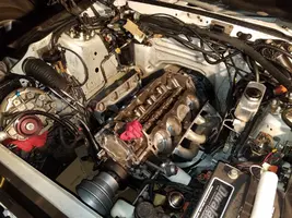
Re-did the head gaskets, while I was at it I de-carboned the motor, re-did everything from the deck out as far as sensors, solenoids, IAC, EGR, ECT, ACT, TFI, Coil, MSD ignition box, adjustable fuel pressure regulator, 60 injectors, Pro M Mass air Calibrated to 60LB, 340 ML fuel pump, 3/8" fuel line, all new vacuum lines, TAB and TAD solenoids, literally everything but the PIP, o2 sensors, and EGR solenoid on the strut tower.

Car ran GREAT once it was back together, BUT I learned the hard way, not enough RTV on the lower intake is no fun. Oil leaks on both sides.

Had to REDO the lower intake Put it all back together, now it runs like a rough, bogged out mess with lean misfires. It's testing 90 for the cylinder test but feels rough to start, I have to put the pedal to the floor to cut off the injectors then it will barely start, and when it's finally warm and stays running the RPM gauge twitches down to 500RPM for a split second.


The cause?? Keep reading.

Here is the kicker and I think what did it, I messed up, bad, I know.

I arched the positive battery post on my strut tower stabilizer bar when I was putting it together the second time.

Twice I did this.

Sparks and all.

Many sparks lol

For a good couple of seconds.

I know that was bad trust me.

I burnt my finger as well. Third degree. On the Allen wrench tool I was using

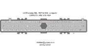
So now I wonder if it's the ECU

After ....

rotating out all of the old pieces that I know worked on almost every part that was new and worked on the first run, I literally changed almost every sensor, tfi, coil, disconnected the igntion box, etc. to make sure I didn't fry one of them, but nothing fixed it. Zero. Nada. Still barely starts then runs like hog wash.

I'm stumped. At this point. Its Super hard to start, I have to floor the pedal to cut off the injectors to get it running, hits like a misfire and stumbled to start, pumping the gas pedal keeping the RPMs up, but smooths a little once it's warm, it has a random twitch is in the RPM gauge/motor at idle down to 500 RPM, even the code reader was being weird giving me code 4 and code 6 which are air bag codes, at one point

But they aren't even in the code book, the reader did seem to short and get shut off during a couple cylinder tests as well... i heard shorting readers can be the the ECU.

Driving it was a huge cutting out like the misfire of all misfires, then it would kick right back in and take off.

Basically, my question is, did I fry the computer? I'm thinking I did.

Or what am I not checking? Something I may have missed doing with the ignition? The PIP maybe?

The codes have been weird and all over when I pulled them while it was running. When I pulled this last time I got

11 for KOEO on both O and C which I usually always get.

Started it for about a minute after this and it lean misfired and stumbled so bad I just shut it off.

Plugged in the reader and had no Memory codes. Still 11 o and c

When I did get it running yesterday,

I got a code 66. Wasn't there before the intake redo either. Could I have fried the Pro-M Mass Air from the battery grounding? I read random codes can be an ECU or timing related issue as well. Is this true?

I got a code 94 but no 44. The cross over tubes and heads were spotless when it went back together. I replaced the TAB and TAD as I read a single code usually means it's the solenoid, Looks like 94 is gone.

Really there is no other codes that have come up outside of those that seems major.

Any help is appreciated.
 

Attachments

  • 20180117_174451.jpg
    20180117_174451.jpg
    444.4 KB · Views: 269
  • 20180409_171259.jpg
    20180409_171259.jpg
    386 KB · Views: 281
  • Sponsors (?)


Code 66 or 157 MAF below minimum test voltage.

Revised 10-Feb-2014 to add 95-95 Mustang code 157 and 94-95 ECC diagram

Insufficient or no voltage from MAF. Dirty MAF element, bad MAF, bad MAF wiring, missing power to MAF. Check for missing +12 volts on this circuit. Check the two links for a wiring diagram to help you find the red wire for computer power relay switched +12 volts. Check for 12 volts between the red and black wires on the MAF heater (usually pins A & B). while the connector is plugged into the MAF. This may require the use of a couple of safety pins to probe the MAF connector from the back side of it.

Computer wiring harness connector, wire side
71316.gif


Computer wiring harness connector, computer side side
88243.gif


Diagrams courtesy of Tmoss and Stang&2Birds

ECC Diagram for 88-90 5.0 Mustangs
88-91_5.0_EEC_Wiring_Diagram.gif


ECC Diagram for 91-93 5.0 Mustangs
91-93_5.0_EEC_Wiring_Diagram.gif


94-95 Diagram for 94-95 5.0 Mustangs[/b]
94-95_5.0_EEC_Wiring_Diagram.gif


How the MAF works

There are three parts in a MAF: the heater, the sensor element and the amplifier. The heater heats the MAF sensor element causing the resistance to increase. The amplifier buffers the MAF output signal and has a resistor that is laser trimmed to provide an output range compatible with the computer's load tables. Changes in RPM causes the airflow to increase or decrease, changing the voltage output.. The increase of air across the MAF sensor element causes it to cool, allowing more voltage to pass and telling the computer to increase the fuel flow. A decrease in airflow causes the MAF sensor element to get warmer, decreasing the voltage and reducing the fuel flow.

The MAF element is secured by 2 screws & has 1 wiring connector. To clean the element, remove it from the MAF housing and spray it down with electronic parts cleaner or non-inflammable brake parts cleaner (same stuff in a bigger can and cheaper too).

89-90 Model cars: Measure the MAF output at pins C & D on the MAF connector (dark blue/orange and tan/light blue) or at pins 50 & 9 on the computer. Be sure to measure the sensor output by measuring across the pins and not between the pins and ground.

91-95 Model cars: Measure the MAF output at pins C & D on the MAF connector light blue/red and tan/light blue) or at pins 50 & 9 on the computer. Be sure to measure the sensor output by measuring across the pins and not between the pins and ground.


At idle = approximately .6 volt
20 MPH = approximately 1.10 volt
40 MPH = approximately 1.70 volt
60 MPH = approximately 2.10 volt

Actually MAF pins C & D float with reference to ground. The signal output of the MAF is a differential amplifier setup. Pins C & D both carry the output signal, but one pin's output is inverted from the other. The difference in signal between C & D is what the computer's input circuit is looking for. The difference in the two outputs helps cancel out electrical noise generated by the ignition system and other components. Since the noise will be of the same polarity, wave shape and magnitude, the differential input of the computer electronically subtracts it from the signal. Then it passes the signal on to an Analog to Digital converter section inside the computer's CPU chip.

Check the resistance of the MAF signal wiring
For the next 2 checks make your measurement with the MAF disconnected from the wiring harness.

Pin D on the MAF wiring harness and pin 50 on the computer (dark blue/orange wire) should be less than 2 ohms. Pin C on the MAF wiring harness and pin 9 on the computer (tan/light blue wire) should be less than 2 ohms.

There should be a minimum of 10K ohms between either pin C or D on the MAF wiring connector and pins A or B.

Reconnect the MAF to the wiring harness and proceed to the next section.

See the following website for some help from Tmoss (diagram designer) & Stang&2Birds (website host) for help on 88-95 wiring http://www.veryuseful.com/mustang/tech/engine/

Ignition switch wiring
http://www.veryuseful.com/mustang/tech/engine/images/IgnitionSwitchWiring.gif

Fuel pump, alternator, ignition & A/C wiring
http://www.veryuseful.com/mustang/tech/engine/images/fuel-alt-links-ign-ac.gif

Computer,. actuator & sensor wiring
http://www.veryuseful.com/mustang/tech/engine/images/88-91_5.0_EEC_Wiring_Diagram.gif

Fuse panel layout
http://www.veryuseful.com/mustang/tech/engine/images/MustangFuseBox.gif

Vacuum routing
http://www.veryuseful.com/mustang/tech/engine/images/mustangFoxFordVacuumDiagram.jpg
 

Attachments

  • 71316.gif
    71316.gif
    33.9 KB · Views: 729
  • 88243.gif
    88243.gif
    7.4 KB · Views: 635
  • 88-91_5.0_EEC_Wiring_Diagram.gif
    88-91_5.0_EEC_Wiring_Diagram.gif
    77 KB · Views: 719
  • 91-93_5.0_EEC_Wiring_Diagram.gif
    91-93_5.0_EEC_Wiring_Diagram.gif
    84.1 KB · Views: 706
  • 94-95_5.0_EEC_Wiring_Diagram.gif
    94-95_5.0_EEC_Wiring_Diagram.gif
    82.7 KB · Views: 957
Last edited:
The computer is pretty rugged; Ford engineers took into consideration that having the battery jumpered or installed backwards or shorted to ground was a real possiblity. There is circuitry inside the computer to protect it from such incidents as described above. The fact that it runs and dumps codes tells you that the computer is working OK.

However, the MAF may be a different story. Check for loose connections and damage to the wiring as a first step.

Code 66 or 157 MAF below minimum test voltage.

Revised 10-Feb-2014 to add 95-95 Mustang code 157 and 94-95 ECC diagram

Insufficient or no voltage from MAF. Dirty MAF element, bad MAF, bad MAF wiring, missing power to MAF. Check for missing +12 volts on this circuit. Check the two links for a wiring diagram to help you find the red wire for computer power relay switched +12 volts. Check for 12 volts between the red and black wires on the MAF heater (usually pins A & B). while the connector is plugged into the MAF. This may require the use of a couple of safety pins to probe the MAF connector from the back side of it.

Computer wiring harness connector, wire side
71316.gif


Computer wiring harness connector, computer side side
88243.gif


Diagrams courtesy of Tmoss and Stang&2Birds

ECC Diagram for 88-90 5.0 Mustangs
88-91_5.0_EEC_Wiring_Diagram.gif


ECC Diagram for 91-93 5.0 Mustangs
91-93_5.0_EEC_Wiring_Diagram.gif


94-95 Diagram for 94-95 5.0 Mustangs[/b]
94-95_5.0_EEC_Wiring_Diagram.gif


How the MAF works

There are three parts in a MAF: the heater, the sensor element and the amplifier. The heater heats the MAF sensor element causing the resistance to increase. The amplifier buffers the MAF output signal and has a resistor that is laser trimmed to provide an output range compatible with the computer's load tables. Changes in RPM causes the airflow to increase or decrease, changing the voltage output.. The increase of air across the MAF sensor element causes it to cool, allowing more voltage to pass and telling the computer to increase the fuel flow. A decrease in airflow causes the MAF sensor element to get warmer, decreasing the voltage and reducing the fuel flow.

The MAF element is secured by 2 screws & has 1 wiring connector. To clean the element, remove it from the MAF housing and spray it down with electronic parts cleaner or non-inflammable brake parts cleaner (same stuff in a bigger can and cheaper too).

89-90 Model cars: Measure the MAF output at pins C & D on the MAF connector (dark blue/orange and tan/light blue) or at pins 50 & 9 on the computer. Be sure to measure the sensor output by measuring across the pins and not between the pins and ground.

91-95 Model cars: Measure the MAF output at pins C & D on the MAF connector light blue/red and tan/light blue) or at pins 50 & 9 on the computer. Be sure to measure the sensor output by measuring across the pins and not between the pins and ground.


At idle = approximately .6 volt
20 MPH = approximately 1.10 volt
40 MPH = approximately 1.70 volt
60 MPH = approximately 2.10 volt

Check the resistance of the MAF signal wiring. Pin D on the MAF and pin 50 on the computer (dark blue/orange wire) should be less than 2 ohms. Pin C on the MAF and pin 9 on the computer (tan/light blue wire) should be less than 2 ohms.

There should be a minimum of 10K ohms between either pin C or D on the MAF wiring connector and pins A or B. Make your measurement with the MAF disconnected from the wiring harness.

Actually MAF pins C & D float with reference to ground. The signal output of the MAF is a differential amplifier setup. Pins C & D both carry the output signal, but one pin's output is inverted from the other. The difference in signal between C & D is what the computer's input circuit is looking for. The difference in the two outputs helps cancel out electrical noise generated by the ignition system and other components. Since the noise will be of the same polarity, wave shape and magnitude, the differential input of the computer electronically subtracts it from the signal. Then it passes the signal on to an Analog to Digital converter section inside the computer's CPU chip.

See the following website for some help from Tmoss (diagram designer) & Stang&2Birds (website host) for help on 88-95 wiring http://www.veryuseful.com/mustang/tech/engine/

Ignition switch wiring
http://www.veryuseful.com/mustang/tech/engine/images/IgnitionSwitchWiring.gif

Fuel pump, alternator, ignition & A/C wiring
http://www.veryuseful.com/mustang/tech/engine/images/fuel-alt-links-ign-ac.gif

Computer,. actuator & sensor wiring
http://www.veryuseful.com/mustang/tech/engine/images/88-91_5.0_EEC_Wiring_Diagram.gif

Fuse panel layout
http://www.veryuseful.com/mustang/tech/engine/images/MustangFuseBox.gif

Vacuum routing
http://www.veryuseful.com/mustang/tech/engine/images/mustangFoxFordVacuumDiagram.jpg

Thank you for the direction and insight! Glad to know the computer may be safe. Worried I fried my new Pro-M Mass Air now lol. Crud.

I'll check it today and post back.
 
The computer is pretty rugged; Ford engineers took into consideration that having the battery jumpered or installed backwards or shorted to ground was a real possiblity. There is circuitry inside the computer to protect it from such incidents as described above. The fact that it runs and dumps codes tells you that the computer is working OK.

However, the MAF may be a different story. Check for loose connections and damage to the wiring as a first step.

Code 66 or 157 MAF below minimum test voltage.

Revised 10-Feb-2014 to add 95-95 Mustang code 157 and 94-95 ECC diagram

Insufficient or no voltage from MAF. Dirty MAF element, bad MAF, bad MAF wiring, missing power to MAF. Check for missing +12 volts on this circuit. Check the two links for a wiring diagram to help you find the red wire for computer power relay switched +12 volts. Check for 12 volts between the red and black wires on the MAF heater (usually pins A & B). while the connector is plugged into the MAF. This may require the use of a couple of safety pins to probe the MAF connector from the back side of it.

Computer wiring harness connector, wire side
71316.gif


Computer wiring harness connector, computer side side
88243.gif


Diagrams courtesy of Tmoss and Stang&2Birds

ECC Diagram for 88-90 5.0 Mustangs
88-91_5.0_EEC_Wiring_Diagram.gif


ECC Diagram for 91-93 5.0 Mustangs
91-93_5.0_EEC_Wiring_Diagram.gif


94-95 Diagram for 94-95 5.0 Mustangs[/b]
94-95_5.0_EEC_Wiring_Diagram.gif


How the MAF works

There are three parts in a MAF: the heater, the sensor element and the amplifier. The heater heats the MAF sensor element causing the resistance to increase. The amplifier buffers the MAF output signal and has a resistor that is laser trimmed to provide an output range compatible with the computer's load tables. Changes in RPM causes the airflow to increase or decrease, changing the voltage output.. The increase of air across the MAF sensor element causes it to cool, allowing more voltage to pass and telling the computer to increase the fuel flow. A decrease in airflow causes the MAF sensor element to get warmer, decreasing the voltage and reducing the fuel flow.

The MAF element is secured by 2 screws & has 1 wiring connector. To clean the element, remove it from the MAF housing and spray it down with electronic parts cleaner or non-inflammable brake parts cleaner (same stuff in a bigger can and cheaper too).

89-90 Model cars: Measure the MAF output at pins C & D on the MAF connector (dark blue/orange and tan/light blue) or at pins 50 & 9 on the computer. Be sure to measure the sensor output by measuring across the pins and not between the pins and ground.

91-95 Model cars: Measure the MAF output at pins C & D on the MAF connector light blue/red and tan/light blue) or at pins 50 & 9 on the computer. Be sure to measure the sensor output by measuring across the pins and not between the pins and ground.


At idle = approximately .6 volt
20 MPH = approximately 1.10 volt
40 MPH = approximately 1.70 volt
60 MPH = approximately 2.10 volt

Check the resistance of the MAF signal wiring. Pin D on the MAF and pin 50 on the computer (dark blue/orange wire) should be less than 2 ohms. Pin C on the MAF and pin 9 on the computer (tan/light blue wire) should be less than 2 ohms.

There should be a minimum of 10K ohms between either pin C or D on the MAF wiring connector and pins A or B. Make your measurement with the MAF disconnected from the wiring harness.

Actually MAF pins C & D float with reference to ground. The signal output of the MAF is a differential amplifier setup. Pins C & D both carry the output signal, but one pin's output is inverted from the other. The difference in signal between C & D is what the computer's input circuit is looking for. The difference in the two outputs helps cancel out electrical noise generated by the ignition system and other components. Since the noise will be of the same polarity, wave shape and magnitude, the differential input of the computer electronically subtracts it from the signal. Then it passes the signal on to an Analog to Digital converter section inside the computer's CPU chip.

See the following website for some help from Tmoss (diagram designer) & Stang&2Birds (website host) for help on 88-95 wiring http://www.veryuseful.com/mustang/tech/engine/

Ignition switch wiring
http://www.veryuseful.com/mustang/tech/engine/images/IgnitionSwitchWiring.gif

Fuel pump, alternator, ignition & A/C wiring
http://www.veryuseful.com/mustang/tech/engine/images/fuel-alt-links-ign-ac.gif

Computer,. actuator & sensor wiring
http://www.veryuseful.com/mustang/tech/engine/images/88-91_5.0_EEC_Wiring_Diagram.gif

Fuse panel layout
http://www.veryuseful.com/mustang/tech/engine/images/MustangFuseBox.gif

Vacuum routing
http://www.veryuseful.com/mustang/tech/engine/images/mustangFoxFordVacuumDiagram.jpg

Alright I have +12 volts between black and red.

Tested the Ohms on pins A and B, harness disconnected, put it on 200M, 20M and 20K, pins A and B show 1.0. Took it down to 2000 ohms got 456 ohms to pin A and B.

Pins C and D at 20k showed 3.8 ohms.

Does this indicate I may have fried the Pro-M?
 
Last edited:
The computer is pretty rugged; Ford engineers took into consideration that having the battery jumpered or installed backwards or shorted to ground was a real possiblity. There is circuitry inside the computer to protect it from such incidents as described above. The fact that it runs and dumps codes tells you that the computer is working OK.

However, the MAF may be a different story. Check for loose connections and damage to the wiring as a first step.

Code 66 or 157 MAF below minimum test voltage.

Revised 10-Feb-2014 to add 95-95 Mustang code 157 and 94-95 ECC diagram

Insufficient or no voltage from MAF. Dirty MAF element, bad MAF, bad MAF wiring, missing power to MAF. Check for missing +12 volts on this circuit. Check the two links for a wiring diagram to help you find the red wire for computer power relay switched +12 volts. Check for 12 volts between the red and black wires on the MAF heater (usually pins A & B). while the connector is plugged into the MAF. This may require the use of a couple of safety pins to probe the MAF connector from the back side of it.

Computer wiring harness connector, wire side
71316.gif


Computer wiring harness connector, computer side side
88243.gif


Diagrams courtesy of Tmoss and Stang&2Birds

ECC Diagram for 88-90 5.0 Mustangs
88-91_5.0_EEC_Wiring_Diagram.gif


ECC Diagram for 91-93 5.0 Mustangs
91-93_5.0_EEC_Wiring_Diagram.gif


94-95 Diagram for 94-95 5.0 Mustangs[/b]
94-95_5.0_EEC_Wiring_Diagram.gif


How the MAF works

There are three parts in a MAF: the heater, the sensor element and the amplifier. The heater heats the MAF sensor element causing the resistance to increase. The amplifier buffers the MAF output signal and has a resistor that is laser trimmed to provide an output range compatible with the computer's load tables. Changes in RPM causes the airflow to increase or decrease, changing the voltage output.. The increase of air across the MAF sensor element causes it to cool, allowing more voltage to pass and telling the computer to increase the fuel flow. A decrease in airflow causes the MAF sensor element to get warmer, decreasing the voltage and reducing the fuel flow.

The MAF element is secured by 2 screws & has 1 wiring connector. To clean the element, remove it from the MAF housing and spray it down with electronic parts cleaner or non-inflammable brake parts cleaner (same stuff in a bigger can and cheaper too).

89-90 Model cars: Measure the MAF output at pins C & D on the MAF connector (dark blue/orange and tan/light blue) or at pins 50 & 9 on the computer. Be sure to measure the sensor output by measuring across the pins and not between the pins and ground.

91-95 Model cars: Measure the MAF output at pins C & D on the MAF connector light blue/red and tan/light blue) or at pins 50 & 9 on the computer. Be sure to measure the sensor output by measuring across the pins and not between the pins and ground.


At idle = approximately .6 volt
20 MPH = approximately 1.10 volt
40 MPH = approximately 1.70 volt
60 MPH = approximately 2.10 volt

Check the resistance of the MAF signal wiring. Pin D on the MAF and pin 50 on the computer (dark blue/orange wire) should be less than 2 ohms. Pin C on the MAF and pin 9 on the computer (tan/light blue wire) should be less than 2 ohms.

There should be a minimum of 10K ohms between either pin C or D on the MAF wiring connector and pins A or B. Make your measurement with the MAF disconnected from the wiring harness.

Actually MAF pins C & D float with reference to ground. The signal output of the MAF is a differential amplifier setup. Pins C & D both carry the output signal, but one pin's output is inverted from the other. The difference in signal between C & D is what the computer's input circuit is looking for. The difference in the two outputs helps cancel out electrical noise generated by the ignition system and other components. Since the noise will be of the same polarity, wave shape and magnitude, the differential input of the computer electronically subtracts it from the signal. Then it passes the signal on to an Analog to Digital converter section inside the computer's CPU chip.

See the following website for some help from Tmoss (diagram designer) & Stang&2Birds (website host) for help on 88-95 wiring http://www.veryuseful.com/mustang/tech/engine/

Ignition switch wiring
http://www.veryuseful.com/mustang/tech/engine/images/IgnitionSwitchWiring.gif

Fuel pump, alternator, ignition & A/C wiring
http://www.veryuseful.com/mustang/tech/engine/images/fuel-alt-links-ign-ac.gif

Computer,. actuator & sensor wiring
http://www.veryuseful.com/mustang/tech/engine/images/88-91_5.0_EEC_Wiring_Diagram.gif

Fuse panel layout
http://www.veryuseful.com/mustang/tech/engine/images/MustangFuseBox.gif

Vacuum routing
http://www.veryuseful.com/mustang/tech/engine/images/mustangFoxFordVacuumDiagram.jpg


When you say "There should be a minimum of 10K ohms between either pin C or D on the MAF wiring connector and pins A or B. Make your measurement with the MAF disconnected from the wiring harness."

Do you mean check the pins on the actual Mass Air sensor itself?
 
When you say "There should be a minimum of 10K ohms between either pin C or D on the MAF wiring connector and pins A or B. Make your measurement with the MAF disconnected from the wiring harness."

Do you mean check the pins on the actual Mass Air sensor itself?

Check the resistance of the MAF signal wiring
For the next 2 checks make your measurement with the MAF disconnected from the wiring harness.

Pin D on the MAF wiring harness and pin 50 on the computer (dark blue/orange wire) should be less than 2 ohms. Pin C on the MAF wiring harness and pin 9 on the computer (tan/light blue wire) should be less than 2 ohms.

There should be a minimum of 10K ohms between either pin C or D on the MAF wiring connector and pins A or B.
 
Last edited:
Check the resistance of the MAF signal wiring
For the next 2 checks make your measurement with the MAF disconnected from the wiring harness.

Pin D on the MAF wiring harness and pin 50 on the computer (dark blue/orange wire) should be less than 2 ohms. Pin C on the MAF wiring harness and pin 9 on the computer (tan/light blue wire) should be less than 2 ohms.

There should be a minimum of 10K ohms between either pin C or D on the MAF wiring connector and pins A or B.

Ok ... D to pin 50 and C to pin 9 are both under 2 ohms

When I test C to D on 200k ohm setting I get 130.5 ohms and I get no reading on any other ohm settings. Picture attached.

Pulled the board, looks pretty good so I think you're right. Good on the computer. Thank god lol

What does not having 10k ohms between either A B and C D mean in this case?

I guess I will have to get it running even tho it runs like crud and then test the volts for the final portion?

Is there any testing I do to the air sensor pins specifically? Seems like everything is testing the car or testing the meter while it's plugged in to the car but nothing specifically for the meter itself, right?


Let me know what you think. Thanks.
 

Attachments

  • 20180415_141421.jpg
    20180415_141421.jpg
    380.4 KB · Views: 267
  • 20180415_131627.jpg
    20180415_131627.jpg
    580.8 KB · Views: 287
  • 20180415_131409.jpg
    20180415_131409.jpg
    411.8 KB · Views: 281
Ok ... D to pin 50 and C to pin 9 are both under 2 ohms

When I test C to D on 200k ohm setting I get 130.5 ohms and I get no reading on any other ohm settings. Picture attached.

Pulled the board, looks pretty good so I think you're right. Good on the computer. Thank god lol

What does not having 10k ohms between either A B and C D mean in this case?

I guess I will have to get it running even tho it runs like crud and then test the volts for the final portion?

Is there any testing I do to the air sensor pins specifically? Seems like everything is testing the car or testing the meter while it's plugged in to the car but nothing specifically for the meter itself, right?


Let me know what you think. Thanks.

Correction, I believe 200k setting means it's 13000k, correct me if I'm wrong. So if that's the case I would be good.
 
Everything you asked about is in the code 66 test path.

89-90 Model cars: Measure the MAF output at pins C & D on the MAF connector (dark blue/orange and tan/light blue) or at pins 50 & 9 on the computer. Be sure to measure the sensor output by measuring across the pins and not between the pins and ground.

91-95 Model cars: Measure the MAF output at pins C & D on the MAF connector light blue/red and tan/light blue) or at pins 50 & 9 on the computer. Be sure to measure the sensor output by measuring across the pins and not between the pins and ground.


At idle = approximately .6 volt
20 MPH = approximately 1.10 volt
40 MPH = approximately 1.70 volt
60 MPH = approximately 2.10 volt

Thank you. I did read this portion. However, it's a son of a gun to get running and lean misfires a ton. I'm worried I'll mess something up. Am I good to push it, get it warm to idle and test it?

There is nothing you can do outside of having the car running?
 
If it will idle OK, try a cylinder balance test...

Cylinder balance test: use this to find dead or weak cylinders:

Revised 09-Sep-2017 Added reminder to write down the stored codes and engine running codes.

The computer has a cylinder balance test that helps locate cylinders with low power output. You’ll need to dump the codes out of the computer and make sure that you have the A/C off, clutch depressed to the floor and the transmission in neutral. Fail to do this and you can’t do the engine running dump codes test that allows you to do the cylinder balance test.

Here's the way to dump the computer codes with only a jumper wire or paper clip and the check engine light, or test light or voltmeter. I’ve used it for years, and it works great. You watch the flashing test lamp or Check Engine Light and count the flashes.

Be sure to turn off the A/C, have the clutch depressed to the floor, and put the transmission in neutral when dumping the codes. Fail to do this and you will generate a code 67 and not be able to dump the Engine Running codes.


Here's how to dump the computer codes with only a jumper wire or paper clip and the check engine light, or test light or voltmeter. I’ve used it for years, and it works great. You watch the flashing test lamp or Check Engine Light and count the flashes.

583775.jpg


583776.jpg


If your car is an 86-88 stang, you'll have to use the test lamp or voltmeter method. There is no functional check engine light on the 86-88's except possibly the Cali Mass Air cars.

583777.gif


The STI has a gray connector shell and a white/red wire. It comes from the same bundle of wires as the self test connector.

89 through 95 cars have a working Check Engine light. Watch it instead of using a test lamp.

583778.gif


The STI has a gray connector shell and a white/red wire. It comes from the same bundle of wires as the self test connector.


WARNING!!! There is a single dark brown connector with a black/orange wire. It is the 12 volt power to the under the hood light. Do not jumper it to the computer test connector. If you do, you will damage the computer.

What to expect:
You should get a code 11 (two single flashes in succession). This says that the computer's internal workings are OK, and that the wiring to put the computer into diagnostic mode is good. No code 11 and you have some wiring problems.
This is crucial: the same wire that provides the ground to dump the codes provides signal ground for the TPS, EGR, ACT and Map/Baro sensors. If it fails, you will have poor performance, economy and drivability problems

Some codes have different answers if the engine is running from the answers that it has when the engine isn't running. It helps a lot to know if you had the engine running when you ran the test.

Dumping the Engine Running codes: The procedure is the same, you dump the codes and then you start the engine with the test jumper in place. Be sure the A/C is off, clutch depressed to the floor and the transmission is in neutral. You'll get an 11, then a 4 and the engine will speed up to do the EGR test. After the engine speed decreases back to idle, it will dump the engine running codes.

Trouble codes are either 2 digit or 3 digit, there are no cars that use both 2 digit codes and 3 digit codes.

Your 86-88 5.0 won't have a working Check Engine Light, so you'll need a test light.
See AutoZone Part Number: 25886 , $10
583779.jpg


Alternate methods:
For those who are intimidated by all the wires & connections, see Actron® for what a typical hand scanner looks like. Normal retail price is about $30 or so at AutoZone or Wal-Mart.

Or for a nicer scanner see www.midwayautosupply.com/Equus-Digital-Ford-Code-Reader/dp/B000EW0KHW Equus - Digital Ford Code Reader 3145.
It has a 3 digit LCD display so that you don’t have to count flashes or beeps.. Cost is $22-$36.
Order it at Walmart for a better price and free shipping
583780.jpg


Write down the codes that the computer outputs since they will give you information on problems that are stored in the computer's memory


Cylinder balance test


If you have idle or IAC/IAB problems and the engine will not idle on its own without mechanically adjusting the base idle speed above 625-750 RPM, this test will fail with random cylinders pointed out every time it runs. The IAC/IAB must be capable of controlling the engine speed to run in the 1300-1500 RPM range. Playing with the base idle speed by adjusting it upwards will not work, the computer has to be able to control the engine speed using the IAC/IAB.

Warm the car's engine up to normal operating temperature. With the test jumper in test position, start the engine and let it stabilize. It should flash a 10 and then a 4 and maybe an 11. If no 11, then there are other codes that will be dumped.

Write down the codes that the computer outputs since they will give you information that the computer found when it is running. These are often different from the stored codes.

One of the first tests it does is to open the EGR all the way, this will cause the engine to stumble and almost die. If the engine dies here then you have EGR problems.
To start the cylinder balance test, briefly floor the accelerator past 2500 RPM and let off the accelerator. The engine will stabilize at about 1300-1450 RPM and the cut off the fuel injectors one at a time. The engine speed will drop briefly and the computer will turn the fuel injector for the cylinder under test back on. Then it starts the process for the next cylinder. When it has sequenced through all 8 injectors, it will flash 9 for everything OK, or the number of the failing cylinder such as 2 for cylinder #2. Quickly pressing the throttle again up to 2500 RPM’s will cause the test to re-run with smaller qualifying figures.
Do it a third time, and if the same cylinder shows up, the cylinder is weak and isn’t putting out power like it should. See the Chilton’s Shop manual for the complete test procedure

See
View: https://www.youtube.com/watch?v=HDXrkKS4jTE
for a visual tour through the process. There is no voice narration so you have to listen carefully for the engine sounds. I posted the link for the benefit of Stangnet members who had questions about how to do a cylinder balance test. I do not own that video and I am not the creator.

Do a compression test on all the cylinders.
Take special note of any cylinder that shows up as weak in the cylinder balance test. Low compression on one of these cylinders rules out the injectors as being the most likely cause of the problem. Look at cylinders that fail the cylinder balance test but have good compression. These cylinders either have a bad injector, bad spark plug or spark plug wire. Move the wire and then the spark plug to another cylinder and run the cylinder balance test again. If it follows the moved wire or spark plug, you have found the problem. If the same cylinder fails the test again, the injector is bad. If different cylinders fail the cylinder balance test, you have ignition problems or wiring problems in the 10 pin black & white electrical connectors located by the EGR.

How to do a compression test:
Only use a compression tester with a screw in adapter for the spark plug hole. The other type leaks too much to get an accurate reading. Your local auto parts store may have a compression tester to rent/loan. If you do mechanic work on your own car on a regular basis, it would be a good tool to add to your collection.

With the engine warmed up, remove all spark plugs and prop the throttle wide open with a plastic screwdriver handle between the throttle butterfly and the throttle housing. Crank the engine until it the gage reading stops increasing. On a cold engine, it will be hard to tell what's good & what's not. Some of the recent posts have numbers ranging from 140-170 PSI. If the compression is low, squirt some oil in the cylinder and do it again – if it comes up, the rings are worn. There should be no more than 10% difference between cylinders. Use a blow down leak test (puts compressed air inside cylinders) on cylinders that have more than 10% difference.

I generally use a big screwdriver handle stuck in the TB between the butterfly and the TB to prop the throttle open. The plastic is soft enough that it won't damage anything and won't get sucked down the intake either.

A battery charger (not the trickle type) is a good thing to have if you haven't driven the car lately or if you have any doubts about the battery's health. Connect it up while you are cranking the engine and it will help keep the starter cranking at a consistent speed from the first cylinder tested to the last cylinder.
 
If it will idle OK, try a cylinder balance test...

Cylinder balance test: use this to find dead or weak cylinders:

Revised 09-Sep-2017 Added reminder to write down the stored codes and engine running codes.

The computer has a cylinder balance test that helps locate cylinders with low power output. You’ll need to dump the codes out of the computer and make sure that you have the A/C off, clutch depressed to the floor and the transmission in neutral. Fail to do this and you can’t do the engine running dump codes test that allows you to do the cylinder balance test.

Here's the way to dump the computer codes with only a jumper wire or paper clip and the check engine light, or test light or voltmeter. I’ve used it for years, and it works great. You watch the flashing test lamp or Check Engine Light and count the flashes.

Be sure to turn off the A/C, have the clutch depressed to the floor, and put the transmission in neutral when dumping the codes. Fail to do this and you will generate a code 67 and not be able to dump the Engine Running codes.


Here's how to dump the computer codes with only a jumper wire or paper clip and the check engine light, or test light or voltmeter. I’ve used it for years, and it works great. You watch the flashing test lamp or Check Engine Light and count the flashes.

583775.jpg


583776.jpg


If your car is an 86-88 stang, you'll have to use the test lamp or voltmeter method. There is no functional check engine light on the 86-88's except possibly the Cali Mass Air cars.

583777.gif


The STI has a gray connector shell and a white/red wire. It comes from the same bundle of wires as the self test connector.

89 through 95 cars have a working Check Engine light. Watch it instead of using a test lamp.

583778.gif


The STI has a gray connector shell and a white/red wire. It comes from the same bundle of wires as the self test connector.


WARNING!!! There is a single dark brown connector with a black/orange wire. It is the 12 volt power to the under the hood light. Do not jumper it to the computer test connector. If you do, you will damage the computer.

What to expect:
You should get a code 11 (two single flashes in succession). This says that the computer's internal workings are OK, and that the wiring to put the computer into diagnostic mode is good. No code 11 and you have some wiring problems.
This is crucial: the same wire that provides the ground to dump the codes provides signal ground for the TPS, EGR, ACT and Map/Baro sensors. If it fails, you will have poor performance, economy and drivability problems

Some codes have different answers if the engine is running from the answers that it has when the engine isn't running. It helps a lot to know if you had the engine running when you ran the test.

Dumping the Engine Running codes: The procedure is the same, you dump the codes and then you start the engine with the test jumper in place. Be sure the A/C is off, clutch depressed to the floor and the transmission is in neutral. You'll get an 11, then a 4 and the engine will speed up to do the EGR test. After the engine speed decreases back to idle, it will dump the engine running codes.

Trouble codes are either 2 digit or 3 digit, there are no cars that use both 2 digit codes and 3 digit codes.

Your 86-88 5.0 won't have a working Check Engine Light, so you'll need a test light.
See AutoZone Part Number: 25886 , $10
583779.jpg


Alternate methods:
For those who are intimidated by all the wires & connections, see Actron® for what a typical hand scanner looks like. Normal retail price is about $30 or so at AutoZone or Wal-Mart.

Or for a nicer scanner see www.midwayautosupply.com/Equus-Digital-Ford-Code-Reader/dp/B000EW0KHW Equus - Digital Ford Code Reader 3145.
It has a 3 digit LCD display so that you don’t have to count flashes or beeps.. Cost is $22-$36.
Order it at Walmart for a better price and free shipping
583780.jpg


Write down the codes that the computer outputs since they will give you information on problems that are stored in the computer's memory


Cylinder balance test

If you have idle or IAC/IAB problems and the engine will not idle on its own without mechanically adjusting the base idle speed above 625-750 RPM, this test will fail with random cylinders pointed out every time it runs. The IAC/IAB must be capable of controlling the engine speed to run in the 1300-1500 RPM range. Playing with the base idle speed by adjusting it upwards will not work, the computer has to be able to control the engine speed using the IAC/IAB.

Warm the car's engine up to normal operating temperature. With the test jumper in test position, start the engine and let it stabilize. It should flash a 10 and then a 4 and maybe an 11. If no 11, then there are other codes that will be dumped.

Write down the codes that the computer outputs since they will give you information that the computer found when it is running. These are often different from the stored codes.

One of the first tests it does is to open the EGR all the way, this will cause the engine to stumble and almost die. If the engine dies here then you have EGR problems.
To start the cylinder balance test, briefly floor the accelerator past 2500 RPM and let off the accelerator. The engine will stabilize at about 1300-1450 RPM and the cut off the fuel injectors one at a time. The engine speed will drop briefly and the computer will turn the fuel injector for the cylinder under test back on. Then it starts the process for the next cylinder. When it has sequenced through all 8 injectors, it will flash 9 for everything OK, or the number of the failing cylinder such as 2 for cylinder #2. Quickly pressing the throttle again up to 2500 RPM’s will cause the test to re-run with smaller qualifying figures.
Do it a third time, and if the same cylinder shows up, the cylinder is weak and isn’t putting out power like it should. See the Chilton’s Shop manual for the complete test procedure

See
View: https://www.youtube.com/watch?v=HDXrkKS4jTE
for a visual tour through the process. There is no voice narration so you have to listen carefully for the engine sounds. I posted the link for the benefit of Stangnet members who had questions about how to do a cylinder balance test. I do not own that video and I am not the creator.

Do a compression test on all the cylinders.
Take special note of any cylinder that shows up as weak in the cylinder balance test. Low compression on one of these cylinders rules out the injectors as being the most likely cause of the problem. Look at cylinders that fail the cylinder balance test but have good compression. These cylinders either have a bad injector, bad spark plug or spark plug wire. Move the wire and then the spark plug to another cylinder and run the cylinder balance test again. If it follows the moved wire or spark plug, you have found the problem. If the same cylinder fails the test again, the injector is bad. If different cylinders fail the cylinder balance test, you have ignition problems or wiring problems in the 10 pin black & white electrical connectors located by the EGR.

How to do a compression test:
Only use a compression tester with a screw in adapter for the spark plug hole. The other type leaks too much to get an accurate reading. Your local auto parts store may have a compression tester to rent/loan. If you do mechanic work on your own car on a regular basis, it would be a good tool to add to your collection.

With the engine warmed up, remove all spark plugs and prop the throttle wide open with a plastic screwdriver handle between the throttle butterfly and the throttle housing. Crank the engine until it the gage reading stops increasing. On a cold engine, it will be hard to tell what's good & what's not. Some of the recent posts have numbers ranging from 140-170 PSI. If the compression is low, squirt some oil in the cylinder and do it again – if it comes up, the rings are worn. There should be no more than 10% difference between cylinders. Use a blow down leak test (puts compressed air inside cylinders) on cylinders that have more than 10% difference.

I generally use a big screwdriver handle stuck in the TB between the butterfly and the TB to prop the throttle open. The plastic is soft enough that it won't damage anything and won't get sucked down the intake either.

A battery charger (not the trickle type) is a good thing to have if you haven't driven the car lately or if you have any doubts about the battery's health. Connect it up while you are cranking the engine and it will help keep the starter cranking at a consistent speed from the first cylinder tested to the last cylinder.


I got it running, code 94 R and 13 R.

Cleaned the Mass Air Sensor before I started it, checked voltage and it was .52 at idle.

Code 66 is gone. So Mass Air must be good I guess?

Cylinder balance test was 90 twice, then my reader shut off randomly. It also didn't read that it was an 8 cyl. Weird behavior with the reader since I grounded it.

I replace the TAB and TAD solenoids already, vacuum lines and cleaned the bypass tube on the back the heads.

Code 94 was there before, but went away, now it's back. Go figure.

Also code 13 may be due to the 340ml fuel pump pushing up the idle, No?

Also I noticed that twitch on the RPM gauge also shuts off the light on the MSD ignition box for that same split second. What wod cause the ignition bpx light to :poo: off?

Side note, I have disconnected it and problem is still there with the idle twitch. So something is shorting somewhere I'm guessing?

Thanks
 
If it will idle OK, try a cylinder balance test...

Cylinder balance test: use this to find dead or weak cylinders:

Revised 09-Sep-2017 Added reminder to write down the stored codes and engine running codes.

The computer has a cylinder balance test that helps locate cylinders with low power output. You’ll need to dump the codes out of the computer and make sure that you have the A/C off, clutch depressed to the floor and the transmission in neutral. Fail to do this and you can’t do the engine running dump codes test that allows you to do the cylinder balance test.

Here's the way to dump the computer codes with only a jumper wire or paper clip and the check engine light, or test light or voltmeter. I’ve used it for years, and it works great. You watch the flashing test lamp or Check Engine Light and count the flashes.

Be sure to turn off the A/C, have the clutch depressed to the floor, and put the transmission in neutral when dumping the codes. Fail to do this and you will generate a code 67 and not be able to dump the Engine Running codes.


Here's how to dump the computer codes with only a jumper wire or paper clip and the check engine light, or test light or voltmeter. I’ve used it for years, and it works great. You watch the flashing test lamp or Check Engine Light and count the flashes.

583775.jpg


583776.jpg


If your car is an 86-88 stang, you'll have to use the test lamp or voltmeter method. There is no functional check engine light on the 86-88's except possibly the Cali Mass Air cars.

583777.gif


The STI has a gray connector shell and a white/red wire. It comes from the same bundle of wires as the self test connector.

89 through 95 cars have a working Check Engine light. Watch it instead of using a test lamp.

583778.gif


The STI has a gray connector shell and a white/red wire. It comes from the same bundle of wires as the self test connector.


WARNING!!! There is a single dark brown connector with a black/orange wire. It is the 12 volt power to the under the hood light. Do not jumper it to the computer test connector. If you do, you will damage the computer.

What to expect:
You should get a code 11 (two single flashes in succession). This says that the computer's internal workings are OK, and that the wiring to put the computer into diagnostic mode is good. No code 11 and you have some wiring problems.
This is crucial: the same wire that provides the ground to dump the codes provides signal ground for the TPS, EGR, ACT and Map/Baro sensors. If it fails, you will have poor performance, economy and drivability problems

Some codes have different answers if the engine is running from the answers that it has when the engine isn't running. It helps a lot to know if you had the engine running when you ran the test.

Dumping the Engine Running codes: The procedure is the same, you dump the codes and then you start the engine with the test jumper in place. Be sure the A/C is off, clutch depressed to the floor and the transmission is in neutral. You'll get an 11, then a 4 and the engine will speed up to do the EGR test. After the engine speed decreases back to idle, it will dump the engine running codes.

Trouble codes are either 2 digit or 3 digit, there are no cars that use both 2 digit codes and 3 digit codes.

Your 86-88 5.0 won't have a working Check Engine Light, so you'll need a test light.
See AutoZone Part Number: 25886 , $10
583779.jpg


Alternate methods:
For those who are intimidated by all the wires & connections, see Actron® for what a typical hand scanner looks like. Normal retail price is about $30 or so at AutoZone or Wal-Mart.

Or for a nicer scanner see www.midwayautosupply.com/Equus-Digital-Ford-Code-Reader/dp/B000EW0KHW Equus - Digital Ford Code Reader 3145.
It has a 3 digit LCD display so that you don’t have to count flashes or beeps.. Cost is $22-$36.
Order it at Walmart for a better price and free shipping
583780.jpg


Write down the codes that the computer outputs since they will give you information on problems that are stored in the computer's memory


Cylinder balance test

If you have idle or IAC/IAB problems and the engine will not idle on its own without mechanically adjusting the base idle speed above 625-750 RPM, this test will fail with random cylinders pointed out every time it runs. The IAC/IAB must be capable of controlling the engine speed to run in the 1300-1500 RPM range. Playing with the base idle speed by adjusting it upwards will not work, the computer has to be able to control the engine speed using the IAC/IAB.

Warm the car's engine up to normal operating temperature. With the test jumper in test position, start the engine and let it stabilize. It should flash a 10 and then a 4 and maybe an 11. If no 11, then there are other codes that will be dumped.

Write down the codes that the computer outputs since they will give you information that the computer found when it is running. These are often different from the stored codes.

One of the first tests it does is to open the EGR all the way, this will cause the engine to stumble and almost die. If the engine dies here then you have EGR problems.
To start the cylinder balance test, briefly floor the accelerator past 2500 RPM and let off the accelerator. The engine will stabilize at about 1300-1450 RPM and the cut off the fuel injectors one at a time. The engine speed will drop briefly and the computer will turn the fuel injector for the cylinder under test back on. Then it starts the process for the next cylinder. When it has sequenced through all 8 injectors, it will flash 9 for everything OK, or the number of the failing cylinder such as 2 for cylinder #2. Quickly pressing the throttle again up to 2500 RPM’s will cause the test to re-run with smaller qualifying figures.
Do it a third time, and if the same cylinder shows up, the cylinder is weak and isn’t putting out power like it should. See the Chilton’s Shop manual for the complete test procedure

See
View: https://www.youtube.com/watch?v=HDXrkKS4jTE
for a visual tour through the process. There is no voice narration so you have to listen carefully for the engine sounds. I posted the link for the benefit of Stangnet members who had questions about how to do a cylinder balance test. I do not own that video and I am not the creator.

Do a compression test on all the cylinders.
Take special note of any cylinder that shows up as weak in the cylinder balance test. Low compression on one of these cylinders rules out the injectors as being the most likely cause of the problem. Look at cylinders that fail the cylinder balance test but have good compression. These cylinders either have a bad injector, bad spark plug or spark plug wire. Move the wire and then the spark plug to another cylinder and run the cylinder balance test again. If it follows the moved wire or spark plug, you have found the problem. If the same cylinder fails the test again, the injector is bad. If different cylinders fail the cylinder balance test, you have ignition problems or wiring problems in the 10 pin black & white electrical connectors located by the EGR.

How to do a compression test:
Only use a compression tester with a screw in adapter for the spark plug hole. The other type leaks too much to get an accurate reading. Your local auto parts store may have a compression tester to rent/loan. If you do mechanic work on your own car on a regular basis, it would be a good tool to add to your collection.

With the engine warmed up, remove all spark plugs and prop the throttle wide open with a plastic screwdriver handle between the throttle butterfly and the throttle housing. Crank the engine until it the gage reading stops increasing. On a cold engine, it will be hard to tell what's good & what's not. Some of the recent posts have numbers ranging from 140-170 PSI. If the compression is low, squirt some oil in the cylinder and do it again – if it comes up, the rings are worn. There should be no more than 10% difference between cylinders. Use a blow down leak test (puts compressed air inside cylinders) on cylinders that have more than 10% difference.

I generally use a big screwdriver handle stuck in the TB between the butterfly and the TB to prop the throttle open. The plastic is soft enough that it won't damage anything and won't get sucked down the intake either.

A battery charger (not the trickle type) is a good thing to have if you haven't driven the car lately or if you have any doubts about the battery's health. Connect it up while you are cranking the engine and it will help keep the starter cranking at a consistent speed from the first cylinder tested to the last cylinder.


Ok I lied l, forgot about KOEO.

Got a code 66c (still), 18 c and 29c

Battery was disconnected for hours so these are all new.