Electrical Foxbody Mustang: Adding Check engine light to 86-88 cars

Mustang5L5

That is…until I whipped out my Bissell
Mod Dude
Feb 18, 2001
43,145
17,841
224
Massachusetts
As some may know, the early Speed Density 86-88 5.0 cars did not come with a functional Check engine light. The 86 cars never had the means to display a CEL. The 87-88 cars do have a spot for the CEL under the tach, and part of the dash wiring. This, however, was solely for the 2.3L Mustangs

The pin on the ECU that matters here is Pin 17. On the '89 and later cars with a functioning CEL, Pin 17 would have a wire going to the EEC4 test connector and a wire going to the gauge cluster light. Pin 17 is a ground that the ECU can switch. By closing the circuit to the dash bulb, the CEL will now light.

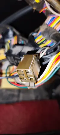
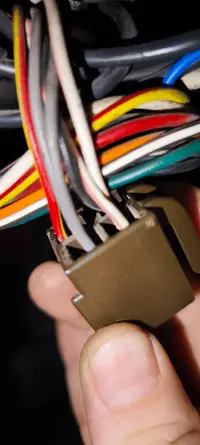
Problem is that on the 87-88 cars, ford left this wiring incomplete, and on 1986 never added the dash wiring. The wire comes from pin 17 into the EEC harness that travels into the engine bay on the passenger side of the firewall, and then travels across the pinch weld to the driver's side of the bay and terminates at the EEC4 plug. There is no connection to the gauge cluster.

The 87-88 cars do have a "bulb test" wiring circuit which will light up the bulbs during the CRANK cycle. So, on the 87-88 cars, if you were to stick a bulb in the cluster, the CEL still won't work. You may see it light up during cranking, but that's because it's the bulb check wiring triggering the light. To make the CEL functional you need to add one wire.

More details below.


For those that need visuals..


View: https://youtu.be/Z_rtHA0Z0fU
 
Last edited:
1986

As mentioned, none of the 1986 models have a Check engine light, so no wiring exists in the dash or a place on the guage cluster for it. If you want a light, you need to mount a bulb somewhere and feed it constant 12V. Then, tap the negative side of it into pin 17 at the ECU, or at the EEC4 diagnostic test port.

The wire route for Pin 17 is a yellow/black wire out of the EEC 60-pin connector and out into the engine bay through the pass side firewall wiring. It then runs along the pinch weld over to the diagnostic test port and terminates there. Tapping your negative wire in here will trigged that CEL bulb when the circuit closes.

As you can see from the wiring diagram, Pin 17 is just a wingle wire out to the connector. 1987 is wired essentially the same way.

To initiate the test, you would jump pin 46 to the STI (pin 48) and your output blinking bulb would be driven by pin 17. Since this is a switched ground, you just need to complete a circuit with a bulb that has 12V+
821A884A-9FC9-49D6-913A-F579CF3C363C.jpeg
 
Last edited:
1987 and 1988

1988 CA MAF cars are excluded from this.
They are wired differently and already have a functional CEL

For the most part, 1987 and 1988 are the same as 1986 as to how the CEL is wired out to the test port. A single yellow/black wire runs from PIN 17 out to the eec test port following the same routing.

The way 87/88 differ from 1986 is that the 2.3L Mustang did have a functional CEL, and therefor there is a spot in the cluster for it. It lacks a bulb, so you will need to add the bulb, but since the dash harness is shared between the 5.0 and the 2.3, it means the wiring partially exists, but terminates somewhere prematurely.

Here is where that wire terminates. C135. The wire runs from the cluster across the dash wiring harness and stops at the green 8-pin connector next to the ECU. A 2.3L would have a wire on both sides of the plug, but on the 5.0 cars, the ECU side of the plug is empty. Ford never completed the circuit here
98548B73-9E1C-4AEE-8161-8602C60D2F32.jpeg

There is one sublte difference between the 1987 and 1988 dash wiring. That would be the addition of a diode to the bulb check circuit on 1988. It appears 1987 was run without the diode. I do not know the consequences of running sand diode, but i put there here as a FYI. The purpose of the black/blue wire is as a bulb check when the key is turned to START. This would make the CEL flash for a second during crank

1987 (click to enlarge)
346F8612-CD7B-42E7-970E-C6FAF7AC9F9E.jpeg

1988 & 1989 (click to enlarge)
27B8EE91-02C1-43E3-AAA6-E44ECB12FCD3.jpeg
 
Last edited:
So with all that mumbo jumbo out of the way, here's how to make the light functional.

1986. Your kinda on your own here as you need to make a bulb circuit and tap the neg side into pin 17. Essentially you need two wires, a bulb&socket and some means to put this bulb in your location of choice (one of the dummy lights?). Find a 12V key on power source and run that to pos side of bulb, and then run neg side of bulb to pin 17. done.

1987 and 1988, you can do this. This is how i did it on my 1988.

First off, you need to pull the cluster to add the bulb. I've heard mixed tales of the bulb being installed on some, and not on other, and only having a plastic holder on other cars. Needless to say, you are likely pulling your cluster and installing a bulb and bulb holder into the cluster.

While back there, you should see this TAN wire. It's on the left cluster plug, at the bottom inside pin position. You'll notice it's paired with a blue/black wire and if you look at the above wiring diagrams (post #3), this is the bulb check circuit. You don't need to do anything here, but while you are adding your bulb, wouldn't hurt to verify this.
7D022CE5-C856-41ED-B81B-78177E39EB39.jpeg


With a bulb installed, you can now pull the pass side kick panel off and find the green 8-pin connector. Our tan wire should be here.

A3BBED0F-D54A-419B-96B6-60EFBDF76BDE.jpeg


And you'll notice the other side of it has no mating wire.
0CED245A-11ED-4827-92A6-844425A5BC63.jpeg
 
Last edited:
At this point, you probably understand what you need to do.

Find the yellow/black wire on Pin 17 of the ecu connector. All you need to do now is install a jumper between the yellow/black and this tan wire.

I used this style connector as i can remove if if i ever need to "turn off" my CEL (for state inspections or other reasons).
CA23C352-5511-4313-8EE2-5A7D64E6CECB.webp


And that's it. Turn the key to ON and the CEL should be on nice and bright

E6642BD7-3364-4E5B-87CA-BAD8362B464A.webp
 
1986 (and older) have four 'dummy lights' on the left portion of the instrument cluster bezel. Once of them (Upshift indicator - third from top) is unused in 1986 so you could use that for an MIL. You could even make it an "Engine" indicator if you got the indicator panel from an earlier Mustang. I think 1984 and earlier have an Engine indicator panel.
 
  • Like
Reactions: Mustang5L5
Has anyone seen this behavior before?Which of these mods likely caused the warning lights to behave incorrectly?

Car: 1988 Convertible GT, speed-density (not MAF).

Before mods:
On KEY-ON, only the upper pair of warning indicators (LOW OIL and LOW COOLANT) would illuminate briefly. From the time I’ve owned the car, only those two ever worked, but I’ve seen videos of other 1988 cars where all four warning lights come on at KEY-ON.

After mods:
On KEY-ON, a newly added “Check Oil” LED in the instrument cluster now illuminates briefly, but it does so together with only the bottom-left indicator (LOW WASHER) — which seems very odd.

Mods performed:
  • While replacing burned/blinking LED bulbs, I also did the Check Engine Light (CEL) mod:
    • Installed an LED in the CEL provision on the RPM panel
    • Jumpered pin 17 from the ECU to the green connector (tan wire) going to the instrument panel
    • The CEL works correctly in diagnostic mode, but it never comes on at KEY-ON
  • Additionally, I noticed a “Check Oil” provision on the instrument cluster and installed an LED there as well
    • This light now comes on for a few seconds at KEY-ON, paired with the LOW WASHER light
 
Check the ribbon cable to the low fluid module. See the below thread. Common ground, and 4 signal wires to each. Make sure the ribbons are in good shape and not folded over.


When you go key-on, all 4 spots should illuminate, PLUS the check oil in the cluster if you've added the bulb. SO it's not that the check oil light is lighting with the low washer fluid light. It's that the other check oil light and the other 2 lights (low coolant, low fuel) aren't coming on too. I'd check your ribbon cable.

1765809446179.webp
 
  • Like
Reactions: snovak
Check the ribbon cable to the low fluid module. See the below thread. Common ground, and 4 signal wires to each. Make sure the ribbons are in good shape and not folded over.
Thnx @Mustang5L5, I was affraid someone will say to pull it put again :-)

Was cleaning up and this guy felt out...I know about extra connector for 2.3l cooler... but anybody maybe know what this Brown connector also behind fuses/right of the steering rod is?

Wires are 2xGY, BK, R/Y and... Seems like W/P or W/BR.
Cant find it anywhere in documentation... found in another topic also but unanswered...thnx
 

Attachments

  • IMG_20251215_191239.webp
    IMG_20251215_191239.webp
    99 KB · Views: 31
  • IMG_20251215_191342.webp
    IMG_20251215_191342.webp
    104.5 KB · Views: 35
  • IMG_20251215_191348.webp
    IMG_20251215_191348.webp
    94.5 KB · Views: 44
See post #11:

Thnx. Actually I saw that topic as mentioned... and my oil indicator works on RPM part of the instrument table...

Both gray, #208 leading to instrument panel, along with a w/pnk, #258 leading to the oil pan sensor, go to that brown connector that was not plugged in to anything, near the lg. harness interior/firewall grommet.
I went thru EVTM and whole circuit 640, but as my low oil indicator works and low oil relay or timing relay looks quite different (4 pins in row) than this plug i got resonable doubt it ain't that.. :-/.
Or it was actually from factory like that...

Any confirmation it actually is low oil relay?
What does it activate?
 
Last edited:
Forget wiring.... check how Your tiny bulbs sit in seat :-(
When checking how bulbs sit I pushed them in and when they are all the way in from whatever reason they LOOSE contact. One must pull them out and insert on...like "first bump" or first clamping feel. They work, all.

SOOOO....beside CEL You can use Check oil also :-(
 

Attachments

  • IMG_20251217_191117.webp
    IMG_20251217_191117.webp
    337 KB · Views: 61
  • IMG_20251217_190422.webp
    IMG_20251217_190422.webp
    109.4 KB · Views: 34