See PIP problems & diagnostic info at the bottom of the PIP section of this post. It seems lately that there are a lot of PIP failures, even in MSD and reman distributors.
MSD means May Suddenly Die, and they have a bad reputation for selling defective merchandise. It would not be unusual to get a DOA unit fresh out of the box. Try to get your money back if you can.
PIP Sensor functionality, testing and replacement:
The PIP is a Hall Effect magnetic sensor that triggers the TFI and injectors. There is a shutter wheel alternately covers and uncovers a fixed magnet as it rotates. The change in the magnetic field triggers the sensor. A failing PIP sensor will often set code 14 in the computer. They are often heat sensitive, increasing the failure rate as the temperature increases.
Some simple checks to do
before replacing the PIP sensor or distributor:
You will need a Multimeter or DVM with good batteries: test or replace them before you get started.. You may also need some extra 16-18 gauge wire to extend the length of the meter’s test leads.
Visual check first: look for chaffed or damaged wiring and loose connector pins in the TFI harness connector.
Check the IDM wiring – dark green/yellow wire from the TFI module to pin 4 on the computer. There is a 22K Ohm resistor in the wiring between the TFI and the computer. Use an ohmmeter to measure the wire resistance from the TFI to the computer. You should see 22,000 ohms +/- 10%.
Check the PIP wiring - dark blue from the TFI module to pin 56 on the computer. Use an ohmmeter to measure the wire resistance from the TFI to the computer. You should see 0.2-1.5 ohms.
Check the SPOUT wiring – yellow/lt green from the TFI module to pin 36 on the computer. Use an ohmmeter to measure the wire resistance from the TFI to the computer. You should see 0.2-1.5 ohms.
Check the black/orange wire from the TFI module to pin 16 on the computer. Use an ohmmeter to measure the wire resistance from the TFI to the computer. You should see 0.2-1.5 ohms.
Check the red/green wire; it should have a steady 12-13 volts with the ignition switch on and the engine not running.
Check the red/blue wire; it should have a steady 12-13 volts with the ignition switch in Start and the engine not running. Watch out for the fan blades when you do this test, since the engine will be cranking.
If you do not find any chaffed or broken wires, high resistance connections or loose pins in the wiring harness, replace the PIP sensor or the distributor.
The PIP sensor is mounted in the bottom of the distributor under the shutter wheel. In stock Ford distributors, you have to press the gear off the distributor shaft to get access to it to replace it.
To remove the gear, first you drive out the roll pin that secures the gear to the shaft. Then you get to press the gear off with a hydraulic press or puller. When you go to press the gear back on, it has to be perfectly lined up with the hole in the gear and shaft. I have been told that the hole for the pin is offset slightly from center and may require some extra examination to get it lined up correctly.
Most guys just end up replacing the distributor with a remanufactured unit for about $75 exchange
PIP problems & diagnostic info
Spark with the SPOUT out, but not with the SPOUT in suggests a PIP problem. The PIP signal level needs to be above 6.5 volts to trigger the computer, but only needs to be 5.75 volts to trigger the TFI module. Hence with a weak PIP signal, you could get spark but no injector pulse. You will need an oscilloscope or graphing DVM to measure the output voltage since it is not a straight DC voltage.
See http://www.wellsmfgcorp.com/pdf/counterp_v8_i2_2004.pdf and http://www.wellsmfgcorp.com/pdf/counterp_v8_i3_2004.pdf for verification of this little detail from Wells, a manufacturer of TFI modules and ignition system products.
How the TFI ignition works in 86-93 model Mustangs:
Tools needed: DVM, noid light, safety pin.
Theory of operation:
The TFI ignition in 86-93 Mustangs has 4 main components: the ignition switch, the coil, the TFI module and the PIP sensor inside the distributor.
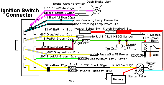
The ignition switch gets power from the two yellow wires that are supplied power by a fuse link located in the wiring harness that connects to the starter solenoid.
Diagram courtesy of Tmoss & Stang&2birds
I.) The coil is mounted on the driver’s side strut tower on most EFI Mustangs. It gets power from a red/green wire and a brown/pink wire from the ignition switch. That wire from the ignition switch feeds a 20 gauge blue fuse link that connects to the red/green wire. The fuse link protects the wiring and the ignition switch, since the fuse link for the two yellow power supply wires has a much higher current rating. Without the smaller fuse link protecting the smaller wiring used in the ignition circuit, a short there would cause the red/green wire to overheat and burn up.
II.) The TFI module is mounted on the side of the distributor and supplies the ground for the coil. Every automotive power supply circuit uses the ground as the return path to carry power back to the negative side of the battery. The TFI switches the tan/yellow wire coming from the coil to ground. It gets power from the red/green wire when the ignition switch is in the Run position.
The red/lt blue wire supplies a signal to turn on more power (dwell time) when the engine is cranking. The increased dwell can cause excessive current draw if the red/blue wire remains energized when the ignition switch is in the Run position. The trigger signal comes from the PIP sensor when cranking and the computer when the engine is running. The SPOUT jumper plug enables computer controlled spark advance. When the SPOUT is removed, spark advance is locked at the setting determined by the mechanical position of the distributor.
III.) The PIP sensor is in the bottom of the distributor under the shutter wheel. It is a Hall effect magnetic sensor that senses a change in the magnetic field when one of the slots in the shutter wheel uncovers the sensor. Then it supplies a pulse that triggers the TFI module to provide a ground to the ignition coil. A bad PIP will often set code 14 in the computer and cause hot start problems. Replacing the PIP sensor requires removal of the distributor and pressing the gear off the distributor shaft to expose the sensor. For most people, a remanufactured distributor ($55-$75) is the solution, since they may not have access to a press.
IV.)
Troubleshooting the ignition system – no spark or weak spark. All the tests are done with the ignition switch in the Run position unless specified otherwise. A safety pin may be used to probe the wiring connectors from the back side.
1.) Check for 12 volts at the yellow wires on the ignition switch. No 12 volts and the fuse link near the starter solenoid has open circuited.
2.) Check for 12 volts on the red/green and brown/pink wires coming out of the ignition switch. No 12 volts, replace the ignition switch.
3.) Check for 12 volts at the ignition coil. No 12 volts and the blue 20 gauge fuse link has open circuited.
4.) Check for 12 volts at the red/green wire on the TFI module. No 12 volts and you have wiring problems.
5.) Remove the small red/blue wire from the starter solenoid (looks like it is stuck on a screw). This is a safety measure to keep the engine from turning while you are making measurements. Have a helper turn the ignition switch to Start and look for 12 volts on the red/lt blue wire on the TFI module. No 12 volts and you will have starting problems, but push starting the car will work OK. No 12 volts, replace the ignition switch. Be sure to reconnect the red/blue wire to the starter when you finish.
6.) Check the red/blue wire to make sure that it has less than 8 volts when the ignition switch is in the Run position.
7.) A noid light available from any auto parts store, is one way to test the PIP pulse. The computer uses the PIP signal to trigger the fuel injectors. The noid light plugs into the fuel injector harness in place of any easily accessible injector. Plug it in and it will flash if the PIP is working. No flash from the noid light and the PIP is suspect. To confirm the PIP is being the source of the non flashing noid light, look for 12 volts on the red injector wiring. Good 12 volts and no flashing noid light means the PIP has failed.
8.) Remove the SPOUT plug from the harness and try to start the engine. If it starts, replace the PIP. This is a common no start condition when the engine is hot.
9.) The TFI module is a go/no go item when you have a no spark/weak spark condition on a cold engine. It either works or it doesn’t.
The TFI failure mode on a running car is usually a high speed miss on a warm engine. Many auto parts stores will test your TFI module for free. Bring along a hair dryer to get it hot while testing it and run several test cycles, since it often gets weak when it heats up.
The coil is somewhat more difficult to pinpoint as a problem. A good coil will make a nice fat blue spark 3/8”-1/2” long. The problem is that one person’s perception of a fat blue spark looks like may not be accurate enough to spot a weak coil. The coil is cheap enough ($13-$16) that having a known good working spare might be a good idea.
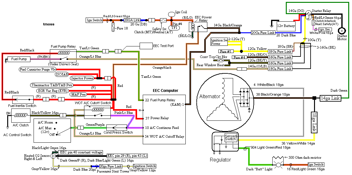
diagram courtesy of Tmoss & Stang&2Birds
See the following website for some help from Tmoss (diagram designer) & Stang&2Birds (website host) for help on 88-95 wiring
http://www.veryuseful.com/mustang/tech/engine/ Everyone should bookmark this site.
Ignition switch wiring
http://www.veryuseful.com/mustang/tech/engine/images/IgnitionSwitchWiring.gif
Fuel, alternator, A/C and ignition wiring
http://www.veryuseful.com/mustang/tech/engine/images/fuel-alt-links-ign-ac.gif
Complete computer, actuator & sensor wiring diagram for 88-91 Mass Air Mustangs
http://www.veryuseful.com/mustang/tech/engine/images/88-91_5.0_EEC_Wiring_Diagram.gif
Vacuum diagram 89-93 Mustangs
http://www.veryuseful.com/mustang/tech/engine/images/mustangFoxFordVacuumDiagram.jpg
HVAC vacuum diagram
http://www.veryuseful.com/mustang/tech/engine/images/Mustang_AC_heat_vacuum_controls.gif
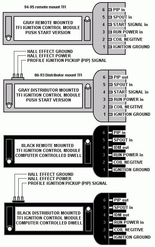
TFI module differences & pinout
http://www.veryuseful.com/mustang/tech/engine/images/TFI_5.0_comparison.gif
When you dump the codes, tool for code 14 or 18 - both point to the PIP and then TFI as the problem.
Dump the codes: Codes may be present even if the Check Engine Light (CEL) isn't on.
Dumping the computer diagnostic codes on 86-95 Mustangs
Revised 26-July-2011. Added need to make sure the clutch is pressed when dumping codes.
Codes may be present even if the check engine light hasn’t come on, so be sure to check for them.
Here's the way to dump the computer codes with only a jumper wire or paper clip and the check engine light, or test light or voltmeter. I’ve used it for years, and it works great. You watch the flashing test lamp or Check Engine Light and count the flashes.
Post the codes you get and I will post 86-93 model 5.0 Mustang specific code definitions and fixes. I do not have a complete listing for 94-95 model 5.0 Mustangs at this time.
Be sure to turn off the A/C, and put the transmission in neutral when dumping the codes. On a manual transmission car, be sure to press the clutch to the floor.
Fail to do this and you will generate a code 67 and not be able to dump the Engine Running codes.
If your car is an 86-88 stang, you'll have to use the test lamp or voltmeter method. There is no functional check engine light on the 86-88's except possibly the Cali Mass Air cars.
The STI has a gray connector shell and a white/red wire. It comes from the same bundle of wires as the self test connector.
89 through 95 cars have a working Check Engine light. Watch it instead of using a test lamp.
The STI has a gray connector shell and a white/red wire. It comes from the same bundle of wires as the self test connector.
WARNING!!! There is a single dark brown connector with a black/orange wire. It is the 12 volt power to the under the hood light. Do not jumper it to the computer test connector. If you do, you will damage the computer.
What to expect:
You should get a code 11 (two single flashes in succession). This says that the computer's internal workings are OK, and that the wiring to put the computer into diagnostic mode is good. No code 11 and you have some wiring problems.
This is crucial: the same wire that provides the ground to dump the codes provides signal ground for the TPS, EGR, ACT and Map/Baro sensors. If it fails, you will have poor performance, economy and driveablity problems
Some codes have different answers if the engine is running from the answers that it has when the engine isn't running. It helps a lot to know if you had the engine running when you ran the test.
Dumping the Engine Running codes: The procedure is the same, you start the engine with the test jumper in place. Be sure the A/C is off, and clutch (if present) is pressed to the floor, and the transmission is in neutral. You'll get an 11, then a 4 and the engine will speed up to do the EGR test. After the engine speed decreases back to idle, it will dump the engine running codes.
Trouble codes are either 2 digit or 3 digit, there are no cars that use both 2 digit codes and 3 digit codes.
Your 86-88 5.0 won't have a working Check Engine Light, so you'll need a test light.
See AutoZone Part Number: 25886 , $10
Alternate methods:
For those who are intimidated by all the wires & connections, see
Actron® for what a typical hand scanner looks like. Normal retail price is about $30 or so at AutoZone or Wal-Mart.
Or for a nicer scanner see
Equus - Digital Ford Code Reader (3145) – It has a 3 digit LCD display so that you don’t have to count flashes or beeps.. Cost is $30.