Use a piece of copper tubing as a splice and solder them together. Cover the splice with heat shrink tubing.
The new battery wire goes back where the old one came off - stock location.
For a battery cut off switch, see
http://www.moroso.com/catalog/categorydisplay.asp?catcode=42225 is the switch
http://www.moroso.com/catalog/images/74102_inst.pdf
Use the super duty switch and the following tech note to wire it and you
will be good to go.
Use the Moroso plan for the alternator wiring and you risk a fire.
The 10 gauge wire they recommend is even less adequate that
the stock Mustang wiring.
There is a solution, but it will require about 40' of 18 gauge green wire.
Wire the battery to the two 1/2" posts as shown in the diagram.
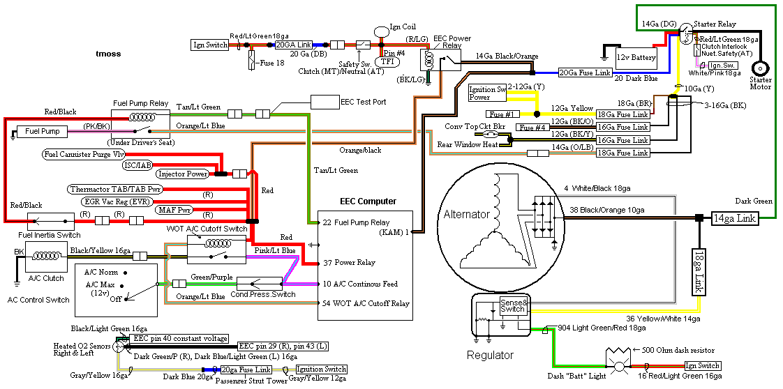
The alternator requires a different approach. On the small alternator plug
there is a green wire. On the diagram it is #904, lt green/red wire that connects
to the alternator and dash light. It is the sense lead that turns the regulator on
when the ignition switch is in the run position. Cut the green wire and solder the
40' of green wire between the two pieces. Use some heat shrink to cover the
splices. See
http://fordfuelinjection.com/?p=7 for some excellent
help on soldering & using heat shrink tubing.
Run the green wire back to the Moroso switch and cut off the excess wire.
Try to run the green wire inside the car and protect it from getting cut or
chaffed. Crimp a 18 gauge ring terminal (red is 18 gauge color code for the crimp
on terminals) on each wire. Bolt one ring terminal to each of the 3/16" studs.
Do not add the jumper between the 1/2" stud and the 3/16" stud as shown it the
Moroso diagram.
How it works:
The green/red wire is the ignition on sense feed to the regulator. It supplies
power to the regulator when the ignition switch is in the run position. Turn
the Moroso switch to off, and the sense voltage goes away, the voltage
regulator shuts off and the alternator quits making power.
See the following website for some help from Tmoss (diagram designer) &
Stang&2Birds (website host) for help on 88-90 wiring and lots more…
http://www.veryuseful.com/mustang/tech/engine/images/IgnitionSwitchWiring.gif
http://www.veryuseful.com/mustang/tech/engine/images/fuel-alt-links-ign-ac.gif
http://www.veryuseful.com/mustang/tech/engine/images/88-91eecPinout.gif
Diagram courtesy of Tmoss and Stang&2birds.
Rear mounted battery ground wiring. Follow this plan and you will have zero
ground problems.
One 1 gauge or 1/0 gauge wire from battery negative post to a clean shiny spot
on the chassis near the battery. Use a 5/16” bolt and bolt it down to make the
rear ground. Use a 1 gauge or 1/0 gauge wire from the rear ground bolt to a clean
shiny spot on the block.
One 4 gauge wire from the block where you connected the battery ground wire to
the chassis ground where the battery was mounted up front. Use a 5/16” bolt
and bolt down the 4 gauge engine to chassis ground, make sure that it the metal
around the bolt is clean & shiny. This is the alternator power ground.
The computer has a dedicated power ground wire with a cylindrical quick connect
(about 2 ½”long by 1” diameter. It comes out of the wiring harness near the
ignition coil & starter solenoid (or relay). Be sure to bolt it to the chassis ground
in the same place as you bolted the alternator power ground.
This is an
absolute don’t overlook it item for EFI cars
Picture courtesy timewarped1972
Crimp or even better, solder the lugs on the all the wire. The local auto stereo
shop will have them if the auto parts store doesn't. Use some heat shrink tubing
to cover the lugs and make things look nice.