Updated 28-Apr-2007 to update fuel pressure regulator failure. Thanks to Red88 RICK for the addition
Many of you are familiar with the "Cranks OK, but No Start Checklist for Fuel Injected Mustangs" checklist and the No Crank Checklist. They are very effective in finding and eliminating the problems by use of a systematic process that checks and eliminates possible causes. This idle problem checklist will use the same troubleshooting strategy and methodology.
By the term surging idle, I mean an idle that wanders up and down more that 100 RPM, or an idle that starts low and goes high and stays there.
The obvious first step is to dump the codes and see what the computer says is wrong…
Here's the link to dump the computer codes with only a jumper wire or paper clip and the check engine light, or test light or voltmeter. I’ve used it for years, and it works great.
See
http://www.troublecodes.net/Ford/
OR
See
http://www.mustangworks.com/articles/electronics/eec-iv_codes.html
IF your car is an 86-88 stang, you'll have to use the test lamp or voltmeter method. There is no functional check engine light on the 86-88's except possibly the 88 model Cali Mass Air cars.
Codes have different answers if the engine is running from the answers that it has when the engine isn't running. It helps a lot to know if you had the engine running when you ran the test.
Trouble codes are either 2 digit or 3 digit, there are no cars that use both 2 digit codes and 3 digit codes.
For those who are intimidated by all the wires & connections, see
http://www.actron.com/product_detail.php?pid=16153 for what a typical hand scanner looks like. Normal retail price is about $30 or so at AutoZone or Wal-Mart.
Or for a nicer scanner see
http://www.midwayautosupply.com/p-7208-equus-digital-ford-code-reader-3145.aspx – It has a 3 digit LCD display so that you don’t have to count flashes or beeps.. Cost is $30.
Find and fix the coded items and that will clear many problems.
So far I have the common items that cause most problems:
1.) Dirty or defective IAB (or IAC) - clean or replace IAB. Some TB's are coated and are marked "Do not clean". If they have no markings, spray them down & use a toothbrush to do the tough places that refuse to come clean. Spray some more and wipe up the mess with a paper towel. The rest will go through the engine with no problems. The stalling when an engine is first cranked up or cold is a clue to a non-functional IAB.
First of all, the idle needs to be adjusted to where the speed is at or below 600 RPM with the IAC disconnected. Then the electrical signal through the IAC can vary the airflow through it under computer control. Remember that the IAC can only add air to increase the base idle speed set by the mechanical adjustment. The 600 RPM base idle speed is what you have after the mechanical adjustment. The IAC increases that speed by supplying more air under computer control to raise the RPM’s to 650-725 RPM’s
Remember that changing the mechanical idle speed adjustment changes the TPS setting too.
This isn't the method Ford uses, but it does work. Do not attempt to set the idle speed until you have fixed all the codes and are sure that there are no vacuum leaks. Warm the engine up to operating temperature, place the transmission in neutral, and set the parking brake. Turn off lights, A/C, all unnecessary electrical loads. Disconnect the IAC electrical connector. Remove the SPOUT plug. This will lock the ignition timing so that the computer won't change the spark advance, which changes the idle speed. Note the engine RPM: use the mechanical adjustment screw under the throttle body to raise or lower the RPM until you get the 600 RPM mark +/- 25 RPM. When you are done, reconnect the IAC electrical connector. Changing the mechanical adjustment changes the TPS, so you will need to set it.
An engine that whose idle speed cannot be set at 600 RPM with the IAC disconnected has mechanical problems. Vacuum leaks are the #1 suspect in this case. A vacuum gauge will help pinpoint both vacuum leaks and improperly adjusted valves. A sticking valve or one adjusted too tight will cause low vacuum and a 5"-8" sweep every time the bad cylinder comes up on compression stroke. An extreme cam can make the 600 RPM set point difficult to set. Contact your cam supplier or manufacturer to get information on idle speed and quality
IAC doesn't work: look for +12 volts at the IAC red wire. Then check for continuity between the white/lt blue wire and pin 21 on the computer. The IAC connector contacts will sometimes corrode and make the IAC not work. The red wire on the IAC is always hot with the engine in run mode. The computer provides a ground for the current for the IAC. It switches the ground on and off, making a square wave with a varying duty cycle. A normal square wave would be on for 50% of the time and off for 50% of the time. When the idle speed is low, the duty cycle increases more than 50% to open the IAC more. When the engine speed is high, it decreases the duty cycle to less than 50% to close the IAC. An old-fashioned dwell meter can be used to check the change: I haven’t tried it personally, but it should work. In theory, it should read ½ scale of whatever range you set it on with a 50% duty cycle. An oscilloscope is even better if you can find someone who has one and will help.
The IAC depends on the computer to provide a ground to make the IAC work. Bad wiring, dirty connections or a failed IAC circuit inside the computer can keep the IAC from adjusting the idle like it should.
2.) Defective TPS - replace TPS. An idle that sticks high and won't come down unless you turn the key off & restart the engine is a sign of a bad TPS.
Setting the TPS: you'll need a good Digital Voltmeter (DVM) to do the job. Set the TPS voltage at .5- 1.1 range. Because of the variables involved with the tolerances of both computer and DVM, I would shoot for somewhere between .6 and 1.0 volts. Unless you have a Fluke or other high grade DVM, the second digit past the decimal point on cheap DVM’s is probably fantasy. Since the computer zeros out the TPS voltage every time it powers up, playing with the settings isn't an effective aid to performance or driveablity. The main purpose of checking the TPS is to make sure it isn't way out of range and causing problems.
The Orange/White wire is the VREF 5 volts from the computer. You use the Dark Green/Lt green wire (TPS signal) and the Black/White wire (TPS ground) to set the TPS. Use a pair of safety pins to probe the TPS connector from the rear of the connector. You may find it a little difficult to make a good connection, but keep trying. Put the safety pins in the Dark Green/Lt green wire and Black/White wire. Make sure the ignition switch is in the Run position but the engine isn't running.
Here’s a TPS tip I got from NoGo50
When you installed the sensor make sure you place it on the peg right and then tighten it down properly. Loosen the back screw a tiny bit so the sensor can pivot and loosen the front screw enough so you can move it just a little in very small increments. I wouldn’t try to adjust it using marks.
(copied from MustangMax, Glendale AZ)
A.) Always adjust the TPS and Idle with the engine at operating temp. Dive it around for a bit if you can and get it nice and warm.
B.) When you probe the leads of the TPS, do not use an engine ground, put the ground probe into the lead of the TPS. You should be connecting both meter probes to the TPS and not one to the TPS and the other to ground.
C.) Always reset the computer whenever you adjust the TPS or clean/change any sensors. I just pull the battery lead for 10 minutes.
D.) The key is to adjust the TPS voltage and reset the computer whenever the idle screw is changed.
The TPS is a variable resistor, must like the volume control knob on a cheap radio. We have all heard them crackle and pop when the volume is adjusted. The TPS sensor has the same problem: wear on the resistor element makes places that create electrical noise. This electrical noise confuses the computer, because it expects to see a smooth increase or decrease as the throttle is opened or closed.
TPS testing: most of the time a failed TPS will set code 23 or 63, but not always. Use either an analog meter or a DVM with an analog bar graph and connect the leads as instructed above. Turn the ignition switch to the Run position, but do not start the engine. Note the voltage with the throttle closed. Slowly open the throttle and watch the voltage increase smoothly, slowly close the throttle and watch the voltage decrease smoothly. If the voltage jumps around and isn’t smooth, the TPS has some worn places in the resistor element. When the throttle is closed, make sure that the voltage is the same as what it was when you started. If it varies more than 10%, the TPS is suspect of being worn in the idle range of its travel.
3.) Vacuum leaks - locate & replace leaky gaskets & hoses. Spend $8 or so at the auto parts store for enough various sizes and lengths of vacuum hose to replace all the vacuum lines. The hard plastic lines get brittle over time and will crack and leak. See
http://www.veryuseful.com/mustang/tech/engine/images/mustangFoxFordVacuumDiagram.jpg and
http://www.veryuseful.com/mustang/tech/engine/images/88Stang5.0Vacuum.gif for vacuum diagrams. The carbon canister plumbing is often damaged or missing, causing vacuum leaks. The big hose coming from the bottom of the upper manifold and going to the front of the engine is for the carbon canister.
To find vacuum leaks around bolted joints, use motor oil in a squirt can. When you find a leak, the oil will be sucked and the engine speed will change. The oil is messy, but works great and will not pose a flash fire hazard. Avoid using flammable fluids like carb cleaner or propane gas – flash fires are not pretty and are very hazardous to your health.
4.) Bad O2 sensors or bad or missing O2 sensor ground - replace o2 sensors and check the ground wire. The ground comes out of the fuel injection wiring harness & is a orange wire with a ring terminal on it. After 60 K miles of usage, the O2 sensors are generally on the downhill side of things.
Because the oxygen sensor generates its own voltage, never apply voltage and never measure resistance of the sensor circuit. To measure voltage signals, use an analog voltmeter with high input impedance, at least 10 megohms. Remember, a digital voltmeter will average a changing voltage Here's a tip: the newer the sensor, the more the voltage changes, swinging from as low as 0.1 volt to as much as 0.9 volt. As an oxygen sensor ages, the voltage changes get smaller and slower - the voltage change lags behind the change in exhaust gas oxygen.
Measuring the O2 sensor voltage at the computer will give you a good idea of how well they are working. You'll have to pull the passenger side kick panel off to gain access to the computer connector. Remove the plastic wiring cover to get to the back side of the wiring. Use a safety pin or paper clip to probe the connections from the rear. The computer pins are 29 (LH O2 with a dark green/pink wire) and 43 (RH O2 with a dark blue/pink wire). Use the ground next to the computer to ground the voltmeter. You can expect to see the voltage switch from .2 volt to .6 volt on the average O2 sensor. More voltage swing is good, less voltage swing is bad.
5.) Insufficient voltage at idle - reduce electrical load, replace or upgrade alternator. Use a good Digital Voltmeter (DVM) to measure the voltage. At 1000 RPM you should see 13.8 – 14.2 volts on a warm engine. Keep in mind that at 650-725 RPM, the output will be less, and may be below the 13.2 volts required to keep the battery charged. This is not good and can cause problems: underdrive pulleys may aggravate the situation.
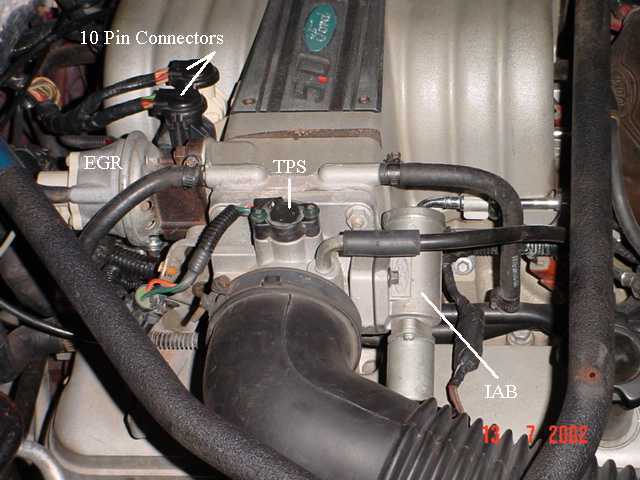
6.) Dirty 10 pin wiring connectors or damaged wiring going to/from the 10 pin salt & pepper shaker wiring connectors.
Diagram courtesy of Tmoss & Stang&2birds
10 pin connector location
10 pin connector contact layout
Clean the 10 pin connectors with electronic parts cleaner or non-inflammable brake parts cleaner (same stuff in a bigger can and cheaper too).
7.) Dirty or defective MAF element: Clean or replace the MAF element. Disconnect the MAF and start the car. If the idle smooths out, then proceed from here. Keep in mind that this does not work on every car.
8.) MAF meter on CAI system that needs clocking or protection from engine compartment air turbulence.
A cone type filter located inside the engine compartment is almost sure to have surge problems due to the hot, turbulent airflow around it. Try cleaning the MAF element & then "clock" the MAF by rotating the entire MAF housing to see if changing its position helps any.
9.) Clogged fuel filter, damaged fuel lines or dirty fuel pump sock. Poor fuel delivery will cause severe problems.
10.) Bad grounds in a computer controlled engine will make all sorts of strange problems.
The secondary power ground is between the back of the intake manifold and the driver's side firewall. It is often missing or loose. It supplies ground for the alternator, A/C compressor clutch and other electrical accessories such as the gauges.
Any car that has a 3G alternator needs a 4 gauge ground wire running from the block to the chassis ground where the battery pigtail ground connects.
The computer has its own dedicated power ground that comes off the ground pigtail on the battery ground wire. Due to it's proximity to the battery, it may become corroded by acid fumes from the battery. It is a black cylinder about 2 1/2" long by 1" diameter with a black/lt green wire.
All the sensors have a common separate ground. This includes the TPS, ACT, EGR, BAP (or MAP), & VSS. This ground terminates inside the computer, but still uses the computer power ground as its source.
See
http://www.fluke.com/application_notes/automotive/circuit.asp?AGID=1&SID=103#volt for help troubleshooting voltage drops across grounds
11.) Dirty or defective ECT and ACT sensors. Look for codes 21, 24, 51, and 54 when you dump the codes. The ACT sensor will get coated with gunk over time and may need to be cleaned.
ACT & ECT test data:
The ACT & ECT have the same thermistor, so the table values are the same
Pin 7 on the computer - ECT signal in. at 176 degrees F it should be .80 volts
Pin 25 on the computer - ACT signal in. at 50 degrees F it should be 3.5 volts. It is a good number if the ACT is mounted in the inlet airbox. If it is mounted in the lower intake manifold, the voltage readings will be lower because of the heat transfer. Here's the table :
68 degrees F = 3.02 v
86 degrees F = 2.62 v
104 degrees F = 2.16 v
122 degrees F = 1.72 v
140 degrees F = 1.35 v
158 degrees F = 1.04 v
176 degrees F = .80 v
194 degrees F = .61
Ohms measures at the computer with the computer disconnected, or at the sensor with the sensor disconnected.
50 degrees F = 58.75 K ohms
68 degrees F = 37.30 K ohms
86 degrees F = 27.27 K ohms
104 degrees F = 16.15 K ohms
122 degrees F = 10.97 K ohms
140 degrees F = 7.60 K ohms
158 degrees F = 5.37 K ohms
176 degrees F = 3.84 K ohms
194 degrees F = 2.80 K ohms
12.) Defective PCV. The PCV is almost impossible to see unless you have the engine out of the car, have the intake manifold off, or you are a snail & have an eyeball on a stalk.

The PCV fits in a rubber grommet that plugs in at the rear of the lower intake manifold. The rubber grommet is notorious for not fitting tight or sealing like it should. It connects to the upper manifold by a 3/8" vacuum hose coming from the rear of the upper intake manifold. The easiest way to find it is to follow the hose with your hand and pull it out of the rubber grommet. Check the screen below the PCV while you have it & the grommet out if you can get to it.
13.) Mismatched aftermarket MAF (Pro-M, Mass Air Systems, C&L, etc) and injector size. The aftermarket MAF must have a matching flow rating for the injectors. If you have 24 lb in injectors, you need a 24 LB aftermarket MAF.
Ford OEM MAF's are matched to the computer and the injector size calibation is done in the computer's program. The Cobra computer is an example of this rule for Ford OEM MAF's. It uses a standard MAF and changes the internal tables to modify the fuel curve for 24 lb injectors.
Some aftermarket devices can modify a mismatch between MAF, computer and injector size, but they are not very common.
14.) VSS sensor defective or wiring damaged. The MAF and Speed Density cruse control equipped cars will have a vehicle speed sensor on the speedo cable pickup. The purpose of the VSS is to increase the idle speed as the car slows to a stop. If the sensor is defective, you can experience stalling as you slow to a stop.
15.) EGR leaking or partially open. An EGR that doesn’t seal or has vacuum applied when the engine is at idle can cause rough idle. Look for EGR code 34 in this case. Disconnect the EGR vacuum and cap the line and observe if the idle improves.
Carbon between EGR the pintle valve and seat can hold the valve off its seat. Remove the EGR valve and clean it with carbon remover. Prior to re-installing see if you can blow air through the flange side of the EGR by mouth. If it leaks, there is carbon stuck on the pintle valve seat, replace the EGR valve ($85-$95).
16.) Over advanced ignition timing can cause the engine to not idle and stall on cold starts. Check the timing with the SPOUT out and it should be in the range of 8-14 degrees BTC.
17.) Engine seem to load up on fuel and may have black smoke at the tailpipe. Fuel pressure regulator failed. Remove the vacuum line from the regulator and inspect for fuel escaping while the pump is running. If fuel is coming out the vacuum port, the regulator has failed. Check the regulator vacuum line for fuel too. Disconnect it from the engine and blow air though it. If you find gas, the regulator has failed.
Thanks to Tmoss & Stang&2birds (http://www.veryuseful.com/mustang/tech/engine/) and http://www.fordfuelinjection.com) for diagrams