1.) Dump the codes as shown below.
2.) Do the alternator check as shown below.
Dump the codes: Codes may be present even if the Check Engine Light (CEL) isn't on.
Dumping the computer diagnostic codes on 86-95 Mustangs
Revised 26-July-2011. Added need to make sure the clutch is pressed when dumping codes.
Codes may be present even if the check engine light hasn’t come on, so be sure to check for them.
Here's the way to dump the computer codes with only a jumper wire or paper clip and the check engine light, or test light or voltmeter. I’ve used it for years, and it works great. You watch the flashing test lamp or Check Engine Light and count the flashes.
Post the codes you get and I will post 86-93 model 5.0 Mustang specific code definitions and fixes. I do not have a complete listing for 94-95 model 5.0 Mustangs at this time.
Be sure to turn off the A/C, and put the transmission in neutral when dumping the codes. On a manual transmission car, be sure to press the clutch to the floor.
Fail to do this and you will generate a code 67 and not be able to dump the Engine Running codes.
If your car is an 86-88 stang, you'll have to use the test lamp or voltmeter method. There is no functional check engine light on the 86-88's except possibly the Cali Mass Air cars.
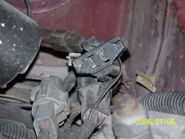
The STI has a gray connector shell and a white/red wire. It comes from the same bundle of wires as the self test connector.
89 through 95 cars have a working Check Engine light. Watch it instead of using a test lamp.
The STI has a gray connector shell and a white/red wire. It comes from the same bundle of wires as the self test connector.
WARNING!!! There is a single dark brown connector with a black/orange wire. It is the 12 volt power to the under the hood light. Do not jumper it to the computer test connector. If you do, you will damage the computer.
What to expect:
You should get a code 11 (two single flashes in succession). This says that the computer's internal workings are OK, and that the wiring to put the computer into diagnostic mode is good. No code 11 and you have some wiring problems.
This is crucial: the same wire that provides the ground to dump the codes provides signal ground for the TPS, EGR, ACT and Map/Baro sensors. If it fails, you will have poor performance, economy and driveablity problems
Some codes have different answers if the engine is running from the answers that it has when the engine isn't running. It helps a lot to know if you had the engine running when you ran the test.
Dumping the Engine Running codes: The procedure is the same, you start the engine with the test jumper in place. Be sure the A/C is off, and clutch (if present) is pressed to the floor, and the transmission is in neutral. You'll get an 11, then a 4 and the engine will speed up to do the EGR test. After the engine speed decreases back to idle, it will dump the engine running codes.
Trouble codes are either 2 digit or 3 digit, there are no cars that use both 2 digit codes and 3 digit codes.
Your 86-88 5.0 won't have a working Check Engine Light, so you'll need a test light.
See AutoZone Part Number: 25886 , $10
Alternate methods:
For those who are intimidated by all the wires & connections, see
Actron® for what a typical hand scanner looks like. Normal retail price is about $30 or so at AutoZone or Wal-Mart.
Or for a nicer scanner see
Equus - Digital Ford Code Reader (3145) – It has a 3 digit LCD display so that you don’t have to count flashes or beeps.. Cost is $30.
Alternator troubleshooting for 86-93 5.0 Mustangs:
Never, never disconnect an alternator from the battery with the engine running. The resulting voltage spike can damage the car's electronics including the alternator.
Revised 15 April 2012 to add simple check for regulator failure in Engine off ignition on, battery fully charged section, item 2.
Do all of these tests in sequence. Do not skip around. The results of each test depend on the results of the previous tests for correct interpretation.
Simple first step: Remove the alternator and take it to your local auto parts store. They can bench test it for free.
Engine off, ignition off, battery fully charged.
1.) Look for 12 volts at the alternator output. No 12 volts and the dark green fuse link between the orange/black wires and the battery side of the starter solenoid has open circuited.
3G alternator: Look for 12 volts at the stud on the back of the alternator where the 4 gauge power feed wire is bolted.
No voltage and the fuse for the 4 gauge power feed wire is open or there are some loose connections.
2.) Look for 12 volts on the yellow/white wire that is the power feed to the regulator. No 12 volts, and the fuse link for the yellow/white wire has open circuited.
Engine off, ignition on, battery fully charged:
1.) Alternator warning light should glow. No glow, bulb has burned out or there is a break in the wiring between the regulator plug and the dash. The warning light supplies an exciter voltage that tells the regulator to turn on. There is a 500 ohm resistor in parallel with the warning light so that if the bulb burns out, the regulator still gets the exciter voltage.
Disconnect the D connector with the 3 wires (yellow/white, white/black and green/red) from the voltage regulator.
Measure the voltage on the Lt green/red wire. It should be 12 volts. No 12 volts and the wire is broken, or the 500 ohm resistor and dash indicator lamp are bad. If the 12 volts is missing, replace the warning lamp. If after replacing the warning lamp, the test fails again, the wiring between the warning lamp and the alternator is faulty. The warning lamp circuit is part of the instrument panel and contains some connectors that may cause problems.
2.) Reconnect the D plug to the alternator
Probe the green/red wire from the rear of the connector and use the battery negative post as a ground. You should see 2.4-2.6 volts. No voltage and the previous tests passed, you have a failed voltage regulator. This is an actual measurement taken from a car with a working electrical system. If you see full or almost full12 volts, the regulator has failed.
Engine on, Ignition on, battery fully charged:
Probe the green/red wire from the rear of the connector and use the battery negative post as a ground. You should see battery voltage minus .25 to 1.0 volt. If the battery measured across the battery is 15.25 volts, you should see 14.50 volts
Familiarize yourself with the following application note from Fluke:
See http://assets.fluke.com/appnotes/automotive/beatbook.pdf for help for help troubleshooting voltage drops across connections and components. .
You will need to do some voltage drop testing of several of the wires.
Start looking for these things:
1.) Bad diode(s) in the alternator - one or more diodes have open circuited and are causing the voltage to drop off as load increases. Remove the alternator and bench test it to confirm or deny this as being the problem.
2.) The secondary power ground is between the back of the intake manifold and the driver's side firewall. It is often missing or loose. It supplies ground for the alternator, A/C compressor clutch and other electrical accessories such as the gauges. Do the voltage drop test as shown in the Fluke tech note link. Measure the voltage drop between the alternator frame and the battery negative post. Watch for an increase in drop as the load increases. Use the Fluke voltage drop figures as guidelines for your decisions.
3.) Bad regulator that does not increase field current as load increases. Remove the alternator and bench test it to confirm or deny this as being the problem.
4.) Bad sense wire - open circuit in sense wiring or high resistance. The yellow/white wire is the voltage sense and power for the field. There is a fuse link embedded in the wiring where it connects to the black/orange wiring that can open up and cause problems. Disconnect the battery negative cable from the battery: this will keep you from making sparks when you do the next step. Then disconnect the yellow/white wire at the alternator and the green fuse link at the starter solenoid/starter relay. Measure the resistance between the alternator end of the yellow/white wire and the green fuse link: you should see less than 1 ohm. Reconnect all the wires when you have completed this step.
5.) Bad power feed wiring from the alternator. Use caution in the next step, since you will need to do it with everything powered up and the engine running. You are going to do the Fluke voltage drop tests on the power feed wiring, fuse links and associated parts. Connect one DMM lead to the battery side of the starter solenoid/starter relay. Carefully probe the backside of the black/orange wire connector where it plugs into the alternator. With the engine off, you should see very little voltage. Start the engine and increase the load on the electrical system. Watch for an increase in drop as the load increases. Use the Fluke voltage drop figures as guidelines for your decisions.
Alternator wiring circuit
Notice the green wire connects to a switched power source. The circuit contains a 500 ohm resistor in series between the switched power and the alternator. Connecting it to switched power keeps the regulator from drawing current when the engine is not running. The resistor limits the current flowing through the wire so that a fuse isn't needed if the wire shorts to ground.
Also notice the sense wire connects to the starter solenoid and it is fused. It connects to the starter solenoid so that it can "sense" the voltage drop across the output wiring from the alternator.


 ton and burns gas like nobodys business