Car won't idle right and I'm out of ideas.

Riddic87

New Member
Mar 5, 2009
2
0
0
Been having the problem for the past 3 weeks. Started rather suddenly and most notable thing that happened at the time frame was we got iced with about 2 inches and then snow.

My car is a '92 LX hatch with a 5.0. Everything is pretty much factory minus exhaust and rear end as far as I know. When I start the car, the idle sounds like I've got the car cammed out. It eventually gets to acting up enough to kill the car and it rolls blue smoke out the exhaust the entire time. The TPS, MAF sensor and O2 sensors have all been replaced by previously known working parts and the O2s are brand new.

I replaced the MAF because if you unplug it, the car goes to limp mode and does perfectly fine, but as soon as you plug it in; it all goes to crap. We also tried regrounding the computer and changed nothing. I'm out of ideas.

I also tried hooking up an EEC tester, but something isn't right because it can't even read. It just sits there with the light on as soon as you plug it in and it never goes off to blink our the code of errors. This was tried by both my tester and by Auto Zones tester.

Any ideas are greatly appreciated. Thanks.
 
Fix the can't get the computer to dump codes first , then see "Surging Idle Checklist for help with all your idle/stall problem

Computer will not go into diagnostic mode on 91-93 model 5.0 Mustangs

How it is supposed to work:
The grey/red wire (pin 46) is signal ground for the computer. It provides a dedicated
ground for the EGR, Baro, ACT, ECT, & TPS sensors as well as the ground to put the
computer into self test mode. If this ground is bad, none of the sensors mentioned will work
properly. That will severely affect the car's performance. You will have hard starting, low power
and drivability problems.
Since it is a dedicated ground, it passes through the computer on its
way to the computer main power ground that terminates at the battery pigtail ground. It should
read less than 1.5 ohms when measured from anyplace on the engine harness with the battery
pigtail ground as the other reference point for the ohmmeter probe.

What sometimes happens is that the test connector grey/red wire gets jumpered to power
which either burns up the wiring or burns the trace off the pc board inside the computer.
That trace connects pins 46 to pins 40 & 60. Only an experienced electronics technician can open
the computer up & repair the trace if it burns up and creates an open circuit.

The STI (Self Test Input ) is jumpered to ground to put the computer into test mode. Jumpering
it to power can produce unknown results, including damage to the computer. The ohm test
simply verifies that there are no breaks in the wiring between the test connector and the computer input.

How to test the wiring :
With the power off, measure the resistance between the computer test ground
(grey/red wire) on the self test connector and battery ground. You should see less than
1.5 ohms.

attachment.php


If that check fails, remove the passenger side kick panel and disconnect the computer
connector. There is a 10 MM bolt that holds it in place. Measure the resistance between
the grey/red wire and pin 46 on the computer wiring connector : it should be less than
1.5 ohms. More that 1.5 ohms is a wiring problem. If it reads 1.5 ohms or less, then the
computer is suspect. On the computer, measure the resistance between pin 46 and pins
40 & 60: it should be less than 1.5 ohms. More that that and the computer’s internal
ground has failed, and the computer needs to be replaced.

If the first ground check was good, there are other wires to check. Measure the
resistance between the STI computer self test connector (red/white wire) and pin 48 on
the computer main connector: it should be less than 1.5 ohms. More that 1.5 ohms is a
wiring problem

The following is a view from the computer side of the computer connector.
eec04.gif


Diagram courtesy of Tmoss & Stang&2birds

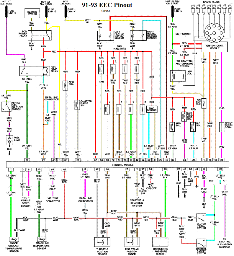
Check out the diagram and notice all the places the grey/red wire goes. Almost every
sensor on the engine except the MAF is connected to it.
91-93_5.0_EEC_Wiring_Diagram.gif


See the following website for some help from Tmoss (diagram designer) & Stang&2Birds
(website host) for help on 88-95 wiring Mustang FAQ - Engine Information

harness02.gif
 
Thanks for the info guys. I'll see what I can come up with, I've been suspect that there was a problem with the computer though. One thing I forgot to mention was that one of the O2 Sensors had been replaced previously and the idiot that did it cut the wires and reconnected them but left over 1" of bare wire on all three and wrapped them together. Wondering if that fed back into the computer or somewhere and did some real damage.