Code 15 - No Keep Alive Memory power to PCM pin 1 or bad PCM (Memory Test
Failure). The voltage to the Keep Alive Memory (KAM) is missing (wiring problem)
or the KAM is bad. The KAM holds all of the settings that the computer "learns" as
it operates and all the stored error codes that are generated as a result of
something malfunctioning while the engine is running. Use a voltmeter to check
the voltage to the pin 1 on the computer - you should always have 12 volts. No
constant 12 volts = bad wiring. If you do always have the 12 volts, then the KAM is
bad and the computer is faulty.
If the computer has to "relearn" all the optimum settings every time it powers up,
the initial 5-30 minutes of operation may exhibit surges, poor low speed performance,
and rough idle.
Note that some aftermarket chips will cause code 15 to set. Remove the chip,
clear the codes and retest.
Before replacing the computer, remove the battery ground cable for about 20
minutes. This will clear all the codes. Retest after several days of running. If the 15
code is gone, then don't worry about it. If it is still there, then you get to do some
troubleshooting.
See the following website for some help from Tmoss (diagram designer) & Stang&2
Birds (website host) for help on 88-95 wiring
Mustang FAQ - Wiring & Engine Info
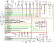
Diagram courtesy of Tmoss & Stang&2birds
http://www.veryuseful.com/mustang/tech/engine/images/IgnitionSwitchWiring.gif
http://www.veryuseful.com/mustang/tech/engine/images/fuel-alt-links-ign-ac.gif
http://www.veryuseful.com/mustang/tech/engine/images/88-91_5.0_EEC_Wiring_Diagram.gif
Code 81 – Secondary Air Injection Diverter Solenoid failure AM2. The solenoid valve located on the back side of the passenger side wheel well is not functional. Possible bad wiring, bad connections, missing or defective solenoid valve. Check the solenoid valve for +12 volts at the Red wire and look for the Lt Green/Black wire to switch from +12 volts to 1 volt or less. The computer controls the valve by providing a ground path on the LT Green/Black wire for the solenoid valve.
With the with the ignition on, look for 12 volts on the red wire on the solenoid connector. No 12 volts and you have wiring problems.
With the engine running, stick a safety pin in the LT Green/Black wire for the solenoid valve & ground it. That should turn the solenoid on and cause air to flow out the port that goes to the pipe connected to the cats. If it doesn't, the valve is bad. If it does cause the airflow to switch, the computer or wiring going to the computer is not signaling the solenoid valve to open.
Putting the computer into self test mode will cause the solenoid valve to toggle. If you listen carefully, you may hear it change states.
Code 82 – Secondary Air Injection Diverter Solenoid failure AM1. Possible bad wiring, bad connections, missing or defective solenoid valve. Check the solenoid valve for +12 volts at the Red wire and look for the Red/White wire to switch from +12 volts to 1 volt or less. The computer controls the valve by providing a ground path on the Red/White wire for the solenoid valve
With the engine running, stick a safety pin in the Red/White wire for the solenoid valve & ground it. That should turn the solenoid on and cause air to flow out the port that goes to the pipe connected to the heads. If it doesn't, the valve is bad. If it does cause the airflow to switch, the computer or wiring going to the computer is not signaling the solenoid valve to open.
Both 81 & 82 codes usually mean that some uneducated person removed the solenoid control valves for the Thermactor Air system in an attempt to make the car faster. It doesn't work that way: no working control valves can cause the cat converters to choke and clog.
Code 85 - CANP solenoid - The Carbon Canister solenoid is inoperative or missing. Check vacuum lines for leaks and cracks. Check electrical wiring for loose connections, damaged wiring and insulation. Check solenoid valve operation by grounding the gray/yellow wire to the solenoid and blowing through it.
The computer provides the ground for the solenoid. The red wire to the solenoid is always energized any time the ignition switch is in the run position.
Charcoal canister plumbing - one 3/8" tube from the bottom of the upper manifold to the rubber hose. Rubber hose connects to one side of the canister solenoid valve. Other side of the solenoid valve connects to one side of the canister. The other side of the canister connects to a rubber hose that connects to a line that goes all the way back to the gas tank. There is an electrical connector coming from the passenger side injector harness near #1 injector that plugs into the canister solenoid valve. It's purpose is to vent the gas tank. The solenoid valve opens at cruse to provide some extra fuel. The canister is normally mounted on the passenger side frame rail near the smog pump pulley.
It does not weigh but a pound or so and helps richen up the cruse mixture. It draws no HP & keeps the car from smelling like gasoline in a closed garage. So with all these good things and no bad ones, why not hook it up & use it?
The purge valve solenoid connector is a dangling wire that is near the ECT sensor and oil filler on the passenger side rocker cover. The actual solenoid valve is down next to the carbon canister. There is about 12"-16" of wire that runs parallel to the canister vent hose that comes off the bottom side of the upper intake manifold. That hose connects one port of the solenoid valve; the other port connects to the carbon canister.
Purge valve solenoid:
The carbon canister is normally mounted on the passenger side frame rail near the smog pump pulley.
Carbon Canister:
Code 95 Key On, Engine not Running - the following test path is for 86-90 model Mustangs.
The 95 code is because at one time or another, the fuel pump relay hiccupped and didn't provide power the pump when the computer told it to run. Sometimes this is a one time thing, other times it is a no run or runs poorly condition.
Using the diagram, check the red/black wire from the fuel pump relay: you should see 12 volts or so. If not, check the inertia switch: on a hatch it is on the driver’s side by the taillight. Look for a black rubber plug that pops out: if you don't find it, then loosen up the plastic trim. Check for voltage on both sides of the switch. If there is voltage on both sides, then check the Pink/black wire on the fuel pump relay: it is the power feed to the fuel pump. No voltage there, check the Orange/Lt blue wire, it is the power feed to the fuel pump relay & has a fuse link in it. If there is good voltage there & at the Pink/black wire, swap the relay.
Some Mass Air conversions neglect to run the extra fuel pump wire, and they always have a 95 code. See
http://www.stangnet.com/tech/maf/massairconversion.html for more information on the Mass Air wiring conversion.
See the following website for some help from Tmoss (diagram designer) & Stang&2Birds (website host) for help on 88-95 wiring
http://www.veryuseful.com/mustang/tech/engine/ Everyone should bookmark this site.
Ignition switch wiring
http://www.veryuseful.com/mustang/tech/engine/images/IgnitionSwitchWiring.gif
Fuel, alternator, A/C and ignition wiring
http://www.veryuseful.com/mustang/tech/engine/images/fuel-alt-links-ign-ac.gif
Complete computer, actuator & sensor wiring diagram for 88-91 Mass Air Mustangs
http://www.veryuseful.com/mustang/tech/engine/images/88-91_5.0_EEC_Wiring_Diagram.gif
Complete computer, actuator & sensor wiring diagram for 91-93 Mass Air Mustangs
http://www.veryuseful.com/mustang/tech/engine/images/91-93_5.0_EEC_Wiring_Diagram.gif
Vacuum diagram 89-93 Mustangs
http://www.veryuseful.com/mustang/tech/engine/images/mustangFoxFordVacuumDiagram.jpg
HVAC vacuum diagram
http://www.veryuseful.com/mustang/tech/engine/images/Mustang_AC_heat_vacuum_controls.gif
TFI module differences & pinout
http://www.veryuseful.com/mustang/tech/engine/images/TFI_5.0_comparison.gif
Fuse box layout
http://www.veryuseful.com/mustang/tech/engine/images/MustangFuseBox.gif
Thermactor Air System
Some review of how it works...
Revised 28-Oct-2009 to correct code definitions and operation.
The Thermactor air pump (smog pump) supplies air to the heads or catalytic converters. This air helps break down the excess HC (hydrocarbons) and CO (carbon monoxide). The air supplied to the catalytic converters helps create the catalytic reaction that changes the HC & CO into CO2 and water vapor. Catalytic converters on 5.0 Mustangs are designed to use the extra air provided by the smog pump. Without the extra air, the catalytic converters will clog and fail.
The Thermactor air pump draws air from an inlet filter in the front of the pump. The smog pump puts air into the heads when the engine is cold and then into the catalytic converters when it is warm. The Thermactor control valves serve to direct the flow. The first valve, TAB (Thermactor Air Bypass) or AM1 valve) either dumps air to the atmosphere or passes it on to the second valve. The second valve, TAD (Thermactor Air Diverter valve or AM2 valve) directs it to the heads or the catalytic converters. Check valves located after the TAB & TAD solenoids prevent hot exhaust gases from damaging the control valves or pump in case of a backfire. The air serves to help consume any unburned hydrocarbons by supplying extra oxygen to the catalytic process. The computer tells the Thermactor Air System to open the Bypass valve at WOT (wide open throttle) minimizing engine drag. This dumps the pump's output to the atmosphere, and reduces the parasitic drag caused by the smog pump to about 2-4 HP at WOT. The Bypass valve also opens during deceleration to reduce or prevent backfires.
Code 44 RH side air not functioning.
Code 94 LH side air not functioning.
The computer uses the change in the O2 sensor readings to detect operation of the Thermactor control valves. When the dump valve opens, it reduces the O2 readings in the exhaust system. Then it closes the dump valve and the O2 readings increase. By toggling the dump valve (TAB), the computer tests for the 44/94 codes.
Failure mode is usually due to a clogged air crossover tube, where one or both sides of the tube clog with carbon. The air crossover tube mounts on the back of the cylinder heads and supplies air to each of the Thermactor air passages cast into the cylinder heads. When the heads do not get the proper air delivery, they set codes 44 & 94, depending on which passage is clogged. It is possible to get both 44 & 94, which would suggest that the air pump or control valves are not working correctly, or the crossover tube is full of carbon or missing.
Computer operation & control for the Thermactor Air System
Automobile computers use current sink technology. They do not source power to any relay, solenoid or actuator like the IAC, fuel pump relay, or fuel injectors. Instead the computer provides a ground path for the positive battery voltage to get back to the battery negative terminal. That flow of power from positive to negative is what provides the energy to make the IAC, fuel pump relay, or fuel injectors work. No ground provided by the computer, then the actuators and relays don't operate.
One side of the any relay/actuator/solenoid in the engine compartment will be connected to a red wire that has 12-14 volts anytime the ignition switch is in the run position. The other side will have 12-14 volts when the relay/actuator/solenoid isn't turned on. Once the computer turns on the clamp side, the voltage on the computer side of the wire will drop down to 1 volt or less.
In order to test the TAD/TAB solenoids, you need to ground the white/red wire on the TAB solenoid or the light green/black wire on the TAD solenoid.
For 94-95 cars: the colors are different. The White/Red wire (TAB control) is White/Orange (Pin 31 on the PCM). The Green/Black wire (TAD control) should be Brown (pin 34 at the PCM). Thanks to HISSIN50 for this tip.
To test the computer, you can use a test light across the TAB or TAD wiring connectors and dump the codes. When you dump the codes, the computer does a self test that toggles every relay/actuator/solenoid on and off. When this happens, the test light will flicker.
Theory of operation:
Catalytic converters consist of two different types of catalysts: Reduction and Oxidation.
The Reduction catalyst is the first converter in a 5.0 Mustang, and the Oxidation converter is the second converter. The Oxidation converter uses the extra air from the smog pump to burn the excess HC. Aftermarket converters that use the smog pump often combine both types of catalysts in one housing. Since all catalytic reactions depend on heat to happen, catalytic converters do not work as efficiently with long tube headers. The extra length of the long tubes reduces the heat available to operate the O2 sensors and the catalytic converters. That will cause emissions problems, and reduce the chances of passing an actual smog test.
Now for the Chemistry...
"The reduction catalyst is the first stage of the catalytic converter. It uses platinum and rhodium to help reduce the NOx emissions. When an NO or NO2 molecule contacts the catalyst, the catalyst rips the nitrogen atom out of the molecule and holds on to it, freeing the oxygen in the form of O2. The nitrogen atoms bond with other nitrogen atoms that are also stuck to the catalyst, forming N2. For example:
2NO => N2 + O2 or 2NO2 => N2 + 2O2
The oxidation catalyst is the second stage of the catalytic converter. It reduces the unburned hydrocarbons and carbon monoxide by burning (oxidizing) them over a platinum and palladium catalyst. This catalyst aids the reaction of the CO and hydrocarbons with the remaining oxygen in the exhaust gas. For example:
2CO + O2 => 2CO2
There are two main types of structures used in catalytic converters -- honeycomb and ceramic beads. Most cars today use a honeycomb structure." Quote courtesy of How Stuff Works (
HowStuffWorks "Catalysts")
What happens when there is no extra air from the smog pump...
As engines age, the quality of tune decreases and wear causes them to burn oil. We have all seem cars that go down the road puffing blue or black smoke from the tailpipe. Oil consumption and poor tune increase the amount of HC the oxidation catalyst has to deal with. The excess HC that the converters cannot oxidize due to lack of extra air becomes a crusty coating inside the honeycomb structure. This effectively reduces the size of the honeycomb passageways and builds up thicker over time and mileage. Continuous usage under such conditions will cause the converter to fail and clog. The extra air provided by the Thermactor Air System (smog pump) is essential for the oxidation process. It oxidizes the added HC from oil consumption and poor tune and keeps the HC levels within acceptable limits.
Newer catalytic converters do not use the Thermactor Air System (smog pump) because they are designed to work with an improved computer system that runs leaner and cleaner
They add an extra set of O2 sensors after the catalytic converters to monitor the oxygen and HC levels. Using this additional information, the improved computer system adjusts the air/fuel mixture for cleaner combustion and reduced emissions. If the computer cannot compensate for the added load of emissions due to wear and poor tune, the catalytic converters will eventually fail and clog. The periodic checks (smog inspections) are supposed to help owners keep track of problems and get them repaired.