Code 34 Or 334 - EGR voltage above closed limit - Failed sensor, carbon between
EGR pintle valve and seat holding the valve off its seat. Remove the EGR valve and
clean it with carbon remover. Prior to re-installing see if you can blow air through
the flange side of the EGR by mouth. If it leaks, there is carbon stuck on the pintle
valve seat, replace the EGR valve ($85-$95).
If the blow by test passes, and you have replaced the sensor, then you have
electrical ground problems. Check the resistance between the black/white wire on
the MAP/BARO sensor and then the black/white wire on the EGR and the same wire
on the TPS. It should be less than 1 ohm. Next check the resistance between the
black/white wire and the negative battery post. It should be less than 1 ohm.
Note that all resistance tests must be done with power off. Measuring
resistance with a circuit powered on will give false readings and possibly damage
the meter.
Let’s put on our Inspector Gadget propeller head beanies and think about how this
works:
The EGR sensor is a variable resistor with ground on one leg and Vref (5 volts) on
the other. Its’ resistance ranges from 4000 to 5500 Ohms measured between Vref
& ground, depending on the sensor. The center connection of the variable resistor
is the slider that moves in response to the amount of vacuum applied. The slider
has some minimum value of resistance greater than 100 ohms so that the
computer always sees a voltage present at its’ input. If the value was 0 ohms,
there would be no voltage output. Then the computer would not be able to
distinguish between a properly functioning sensor and one that had a broken wire
or bad connection. The EGR I have in hand reads 700 Ohms between the slider
(EPV) and ground (SIG RTN) at rest with no vacuum applied. The EGR valve or
sensor may cause the voltage to be above closed limits due to the manufacturing
tolerances that cause the EGR sensor to rest at a higher position than it should.
This will affect idle quality by diluting the intake air charge
Code 85 - CANP solenoid - The Carbon Canister solenoid is inoperative. Check
vacuum lines for leaks and cracks. Check electrical wiring for loose connections,
damaged wiring and insulation. Check solenoid valve operation by grounding the
gray/yellow wire to the solenoid and blowing through it.
The computer provides the ground for the solenoid. The red wire to the solenoid is
always energized any time the ignition switch is in the run position.
Charcoal canister plumbing - one 3/8" tube from the bottom of the upper manifold
to the rubber hose. Rubber hose connects to one side of the canister solenoid
valve. Other side of the solenoid valve connects to one side of the canister. The
other side of the canister connects to a rubber hose that connects to a line that
goes all the way back to the gas tank. There is an electrical connector coming from
the passenger side injector harness near #1 injector that plugs into the canister
solenoid valve. It's purpose is to vent the gas tank. The solenoid valve opens at
cruse to provide some extra fuel.
It does not weigh but a pound or so and helps richen up the cruse mixture. It
draws no HP & keeps the car from smelling like gasoline in a closed garage. So with
all these good things and no bad ones, why not hook it up & use it?
Code 15 - No Keep Alive Memory power to PCM pin 1 or bad PCM (Memory Test
Failure). The voltage to the Keep Alive Memory (KAM) is missing (wiring problem)
or the KAM is bad. The KAM holds all of the settings that the computer "learns" as
it operates and all the stored error codes that are generated as a result of
something malfunctioning while the engine is running. Use a voltmeter to check
the voltage to the pin 1 on the computer - you should always have 12 volts. No
constant 12 volts = bad wiring. If you do always have the 12 volts, then the KAM is
bad and the computer is faulty.
If the computer has to "relearn" all the optimum settings every time it powers up,
the initial 5-30 minutes of operation may exhibit surges, poor low speed performance,
and rough idle.
Note that some aftermarket chips will cause code 15 to set. Remove the chip,
clear the codes and retest.
Before replacing the computer, remove the battery ground cable for about 20
minutes. This will clear all the codes. Retest after several days of running. If the 15
code is gone, then don't worry about it. If it is still there, then you get to do some
troubleshooting.
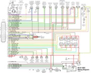
Wiring diagrams for the proper model years are next…
For 86 models see
http://www.autozone.com/images/cds/gif/large/0900823d80167158.gif
For 87 models see
http://www.autozone.com/images/cds/gif/large/0900823d8016715e.gif
For 88 models see
http://www.autozone.com/images/cds/gif/large/0900823d80167162.gif
For 89-90 models see
http://www.autozone.com/images/cds/gif/large/0900823d8019595f.gif
For 91-93 models see
http://www.autozone.com/images/cds/gif/large/0900823d80195960.gif
See the following website for some help from Tmoss (diagram designer) & Stang&2
Birds (website host) for help on 88-95 wiring
http://www.veryuseful.com/mustang/tech/engine/
Diagram courtesy of Tmoss & Stang&2birds
http://www.veryuseful.com/mustang/tech/engine/images/IgnitionSwitchWiring.gif
http://www.veryuseful.com/mustang/tech/engine/images/fuel-alt-links-ign-ac.gif
http://www.veryuseful.com/mustang/tech/engine/images/88-91_5.0_EEC_Wiring_Diagram.gif