E.C.U problem. Please Help!

dillonsuperman2

New Member
Sep 6, 2011
2
0
0
I have a 1991 5.0 mustang with alot of bolt ons. Everything was running smooth until i turned it on one morning and it wasnt running right. After several days of investigation i found that it was my front passenger fuel injector. I hooked a noid tester up to it and it didnt light up. I thought it was the wiring until my friend hooked a circuit tester up to it and it lit up. He said the ecu wasnt grounded right so the ecu must be going bad. All i want to know is if i need a new ecu or if that doent sound like the problem. the fuel injectors are new 24lb and again, the noid light didnt light up but the circuit tester did when grounded to something and stuck in the pigtail of that fuel injector. Its been like this for a while now because i cant figure out whats wrong with it and dont have the money to guess and check. Any help would be appreciated. Thank you in advance.
Dillon
 
Step 1.) Dump the codes

Dumping the computer diagnostic codes on 86-95 Mustangs

Revised 26-July-2011. Added need to make sure the clutch is pressed when dumping codes.

Here's the way to dump the computer codes with only a jumper wire or paper clip and the check engine light, or test light or voltmeter. I’ve used it for years, and it works great. You watch the flashing test lamp or Check Engine Light and count the flashes.

Post the codes you get and I will post 86-93 model 5.0 Mustang specific code definitions and fixes. I do not have a complete listing for 94-95 model 5.0 Mustangs at this time.

Be sure to turn off the A/C, and put the transmission in neutral when dumping the codes. On a manual transmission car, be sure to press the clutch to the floor.
Fail to do this and you will generate a code 67 and not be able to dump the Engine Running codes.

Underhoodpictures007-01.webp


Underhoodpictures010.webp


If your car is an 86-88 stang, you'll have to use the test lamp or voltmeter method. There is no functional check engine light on the 86-88's except possibly the Cali Mass Air cars.

attachment.php


The STI has a gray connector shell and a white/red wire. It comes from the same bundle of wires as the self test connector.

89 through 95 cars have a working Check Engine light. Watch it instead of using a test lamp.

attachment.php


The STI has a gray connector shell and a white/red wire. It comes from the same bundle of wires as the self test connector.


WARNING!!! There is a single dark brown connector with a black/orange wire. It is the 12 volt power to the under the hood light. Do not jumper it to the computer test connector. If you do, you will damage the computer.

What to expect:
You should get a code 11 (two single flashes in succession). This says that the computer's internal workings are OK, and that the wiring to put the computer into diagnostic mode is good. No code 11 and you have some wiring problems. This is crucial: the same wire that provides the ground to dump the codes provides signal ground for the TPS, EGR, ACT and Map/Baro sensors. If it fails, you will have poor performance, economy and driveablity problems

Some codes have different answers if the engine is running from the answers that it has when the engine isn't running. It helps a lot to know if you had the engine running when you ran the test.

Dumping the Engine Running codes: The procedure is the same, you start the engine with the test jumper in place. Be sure the A/C is off, and clutch (if present) is pressed to the floor, and the transmission is in neutral. You'll get an 11, then a 4 and the engine will speed up to do the EGR test. After the engine speed decreases back to idle, it will dump the engine running codes.

Trouble codes are either 2 digit or 3 digit, there are no cars that use both 2 digit codes and 3 digit codes.

Alternate methods:
For those who are intimidated by all the wires & connections, see Actron® for what a typical hand scanner looks like. Normal retail price is about $30 or so at AutoZone or Wal-Mart.

Or for a nicer scanner see Equus - Digital Ford Code Reader (3145) – It has a 3 digit LCD display so that you don’t have to count flashes or beeps.. Cost is $30.
Or for a nicer scanner see http://www.midwayautosupply.com/p-7208-equus-digital-ford-code-reader-3145.aspx– It has a 3 digit LCD display so that you don’t have to count flashes or beeps.. Cost is $30.

Step 2.) Fix the codes.
Post your code results here and I will try to help.


Step 13.) check the injector circuit
Fuel injectors inoperative, one or more injectors either on all the time or will not squirt.

Revised 27-Jan-2008 to include expanded testing for proper power to injector wiring


Tools needed: Noid light, Multimeter (volts & ohms), 10 MM socket &
extension, & ratchet.

Note: Do all of the steps and do them in order. The results of the
subsequent tests are based on the prior tests being successfully passed.


1.) Each injector has a red power wire to provide power to the injector. Turn the ignition switch to Run and remove each injector electrical connector and use the multimeter to check for 12 volts on the red wire. Each injector should have 12 volts +/- .5 volt. More voltage is always better than less voltage. No 12 volts on a singe injector and the wiring for that injector is broken inside the engine fuel injector harness.

No 12 volts on all injectors:
A.) Check for a bad connection at the 10 pin connector. Check for 12 volts at red wire on the MAF or TAD/TAB solenoids mounted on the aft side of the passenger strut tower. Good 12 volts
there and you have a wiring problem with the 10 pin connectors or associated wiring.

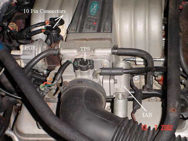
See the graphic for the location of the 10 pin connectors:
TPS_IAB_Pic.webp


See the graphic for the 10 pin connector circuit layout.
harness02.gif


The injector power pin is the VPWR pin in the black 10 pin connector.


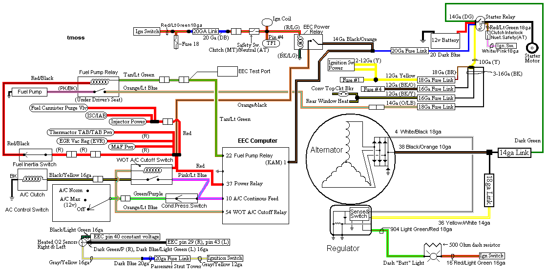
B.) Bad ECC power relay. The relay is on top of the computer, it provides power to the fuel injector system. It is somewhat difficult to get to, since it requires you to remove the computer from its 2 bolt mounting.. If the relay or socket is bad, you will not have 12 volts on any of the red wires in the engine compartment or to pins 37/57 on the computer. The pins 37/57 are the main power feed to the computer.

fuel-alt-links-ign-ac.gif


C.) Blown fuse link – The blue fuse link for the computer is up near the starter solenoid. Check for no 12 volts on the ECC relay socket or computer black/orange wires. No 12 volts and the fuse link is blown open. If the fuse link blows, there is no power for any of the computer functions.

D.) Bad wiring. Broken or damaged red wire to the chassis side of the 10 pin connectors.


Some basics about the computer:
Remember that the computer does not supply power for any actuator or relay. It provides the ground necessary to complete the circuit. That means one side of the circuit will always be hot, and the other side will go to ground or below 1 volt as the computer switches on that circuit.


2.) Get a noid light form AutoZone or other auto parts store, or even better a set of them.

big22132.jpg

This set is from http://www.toolking.com/ProductInfo.aspx?productid=12492 and costs about $12-$14.

3.) Use the noid light to determine that the injector pulses and isn’t stuck in the on position.
It you have a set of them install all of them and compare the pulse intensity. Install the noid lights,
turn the ignition switch to Run and crank the engine. A light that doesn’t pulse and stays on has a
short to ground in the computer side of the circuit. That can be either a wiring fault or a failed computer.
If this is the case, remove the passenger side lick panel and disconnect the computer connector.
There is one 10 MM bolt holding it in place. Pull the connector all the way out of the computer so that you can see the computer side pins.
eec04.gif


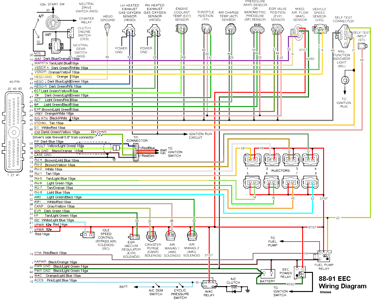
Use the list from the graphic below to find the fuel injector pins for the injectors that didn’t turn the noid light off.

88-91_5.0_EEC_Wiring_Diagram.gif


4.) Set the multimeter to low scale Ohms and measure between the computer ground located below the computer and the suspect fuel injector pins. You should see greater than 100 K Ohms resistance. If you see less than 100 Ohms, the wiring between the injector and the computer has a short to ground and needs service. Check the harness and look for damage, kinks or frayed spots.

5.) A single noid light that never turns on is either a wiring fault, or a failed computer. Either the injector has no DC power or the computer has failed and cannot switch the injector circuit to ground. Determine if the injector has power by using the multimeter to check for 12 volts on the red
wire on the suspect injector connector. No 12 volts and you have a wiring fault. Check the harness and look for damage, kinks or frayed spots. Check the 10 pin salt & pepper shaker connectors for bent pins, corrosion and damage.

If none of the noid lights flash and you have 12 volts at each injector, check to see that you have good spark. Before you even think about replacing the computer, see step 6.

Next Check the fuel injector wiring end to end. Each fuel injector has a red wire (power) and an non-read wire (computer controlled ground). Set the multimeter to low ohms and measure each non red fuel injector wire from the fuel injector connector to the matching pin on the computer connector.
You should see less than 2 Ohms. More than that means a bad connection or bad wiring.


6.) Use an ohmmeter set on the low resistance scale and measure the resistance of each injector across the two contacts inside the electrical connector. You should see between 11-16 ohms. More or less than that is a bad injector. Next measure between either one of the contacts and the metal on the injector body. You should see greater than 100,000 ohms. Don’t hold the metal probe tips with your bare hands when you make this measurement. It will give incorrect results if you do.

Once you have determined that the suspect injectors have good power and good wiring, the computer is the likely suspect, since a ground is required to complete a circuit and make it function. The computer provides the ground: if doesn’t, then the noid light will not flash.

7) If you have gotten this far, then the problem is likely ignition related. Remember the noid test using all of the noid lights? All of them were supposed to be equally bright. Since you have already tested all the electrical side of the fuel injector circuit, the one remaining common item is
the pip sensor inside the distributor. A failing pip sensor, damaged shutter wheel or bent distributor shaft could all cause the pulse delivered to the injectors to be faulty. A bad pip sensor will cause all the injectors not to fire and you will have no spark. Dumping the codes will show a code 14.


8) Spark plugs indicate one or more cylinders not firing: use the multimeter to measure the resistance of the spark plug wires. The wires should measure 2000 ohms perfoot of length. A 2 foot wire would be 4000 ohms and a 3 foot wire would be 6000 ohms. Some Taylor and Accel wires
have metal cores and will measure much less: that’s OK. Next examine the spark plug wires very carefully for burn spots, cracks and damaged insulation. One good thing to try is to start the engine while the car is a very dark area, open the hood and look for sparks or blue glow. They indicate the electricity is leaking out of the spark plug wires.

Thanks to Tmoss & Stang&2birds at Mustang FAQ - Wiring & Engine Info for some of the graphics

Thanks also to Ford Fuel Injection for some of the graphics.
 

Attachments

  • Underhoodpictures007-01.webp
    Underhoodpictures007-01.webp
    49 KB · Views: 160
  • Underhoodpictures010.webp
    Underhoodpictures010.webp
    71.3 KB · Views: 176
  • Like
Reactions: Blakfoot
If the "ECU must not be grounding right" why not check the ECU ground? It would be more likely for there to be a bad ground than the ECU going bad. Check the ECU pinout Joe just posted and start testing wires.
 
Step 1.) Dump the codes

Dumping the computer diagnostic codes on 86-95 Mustangs

Revised 26-July-2011. Added need to make sure the clutch is pressed when dumping codes.

Here's the way to dump the computer codes with only a jumper wire or paper clip and the check engine light, or test light or voltmeter. I’ve used it for years, and it works great. You watch the flashing test lamp or Check Engine Light and count the flashes.

Post the codes you get and I will post 86-93 model 5.0 Mustang specific code definitions and fixes. I do not have a complete listing for 94-95 model 5.0 Mustangs at this time.

Be sure to turn off the A/C, and put the transmission in neutral when dumping the codes. On a manual transmission car, be sure to press the clutch to the floor.
Fail to do this and you will generate a code 67 and not be able to dump the Engine Running codes.

Underhoodpictures007-01.webp


Underhoodpictures010.webp


If your car is an 86-88 stang, you'll have to use the test lamp or voltmeter method. There is no functional check engine light on the 86-88's except possibly the Cali Mass Air cars.

attachment.php


The STI has a gray connector shell and a white/red wire. It comes from the same bundle of wires as the self test connector.

89 through 95 cars have a working Check Engine light. Watch it instead of using a test lamp.

attachment.php


The STI has a gray connector shell and a white/red wire. It comes from the same bundle of wires as the self test connector.


WARNING!!! There is a single dark brown connector with a black/orange wire. It is the 12 volt power to the under the hood light. Do not jumper it to the computer test connector. If you do, you will damage the computer.

What to expect:
You should get a code 11 (two single flashes in succession). This says that the computer's internal workings are OK, and that the wiring to put the computer into diagnostic mode is good. No code 11 and you have some wiring problems. This is crucial: the same wire that provides the ground to dump the codes provides signal ground for the TPS, EGR, ACT and Map/Baro sensors. If it fails, you will have poor performance, economy and driveablity problems

Some codes have different answers if the engine is running from the answers that it has when the engine isn't running. It helps a lot to know if you had the engine running when you ran the test.

Dumping the Engine Running codes: The procedure is the same, you start the engine with the test jumper in place. Be sure the A/C is off, and clutch (if present) is pressed to the floor, and the transmission is in neutral. You'll get an 11, then a 4 and the engine will speed up to do the EGR test. After the engine speed decreases back to idle, it will dump the engine running codes.

Trouble codes are either 2 digit or 3 digit, there are no cars that use both 2 digit codes and 3 digit codes.

Alternate methods:
For those who are intimidated by all the wires & connections, see Actron® for what a typical hand scanner looks like. Normal retail price is about $30 or so at AutoZone or Wal-Mart.

Or for a nicer scanner see Equus - Digital Ford Code Reader (3145) – It has a 3 digit LCD display so that you don’t have to count flashes or beeps.. Cost is $30.
Or for a nicer scanner see http://www.midwayautosupply.com/p-7208-equus-digital-ford-code-reader-3145.aspx– It has a 3 digit LCD display so that you don’t have to count flashes or beeps.. Cost is $30.

Step 2.) Fix the codes.
Post your code results here and I will try to help.


Step 13.) check the injector circuit
Fuel injectors inoperative, one or more injectors either on all the time or will not squirt.

Revised 27-Jan-2008 to include expanded testing for proper power to injector wiring

Tools needed: Noid light, Multimeter (volts & ohms), 10 MM socket &
extension, & ratchet.

Note: Do all of the steps and do them in order. The results of the
subsequent tests are based on the prior tests being successfully passed.

1.) Each injector has a red power wire to provide power to the injector. Turn the ignition switch to Run and remove each injector electrical connector and use the multimeter to check for 12 volts on the red wire. Each injector should have 12 volts +/- .5 volt. More voltage is always better than less voltage. No 12 volts on a singe injector and the wiring for that injector is broken inside the engine fuel injector harness.

No 12 volts on all injectors:
A.) Check for a bad connection at the 10 pin connector. Check for 12 volts at red wire on the MAF or TAD/TAB solenoids mounted on the aft side of the passenger strut tower. Good 12 volts
there and you have a wiring problem with the 10 pin connectors or associated wiring.

See the graphic for the location of the 10 pin connectors:
TPS_IAB_Pic.jpg


See the graphic for the 10 pin connector circuit layout.
harness02.gif


The injector power pin is the VPWR pin in the black 10 pin connector.

B.) Bad ECC power relay. The relay is on top of the computer, it provides power to the fuel injector system. It is somewhat difficult to get to, since it requires you to remove the computer from its 2 bolt mounting.. If the relay or socket is bad, you will not have 12 volts on any of the red wires in the engine compartment or to pins 37/57 on the computer. The pins 37/57 are the main power feed to the computer.

fuel-alt-links-ign-ac.gif


C.) Blown fuse link – The blue fuse link for the computer is up near the starter solenoid. Check for no 12 volts on the ECC relay socket or computer black/orange wires. No 12 volts and the fuse link is blown open. If the fuse link blows, there is no power for any of the computer functions.

D.) Bad wiring. Broken or damaged red wire to the chassis side of the 10 pin connectors.


Some basics about the computer:
Remember that the computer does not supply power for any actuator or relay. It provides the ground necessary to complete the circuit. That means one side of the circuit will always be hot, and the other side will go to ground or below 1 volt as the computer switches on that circuit.

2.) Get a noid light form AutoZone or other auto parts store, or even better a set of them.

big22132.jpg

This set is from http://www.toolking.com/ProductInfo.aspx?productid=12492 and costs about $12-$14.

3.) Use the noid light to determine that the injector pulses and isn’t stuck in the on position.
It you have a set of them install all of them and compare the pulse intensity. Install the noid lights,
turn the ignition switch to Run and crank the engine. A light that doesn’t pulse and stays on has a
short to ground in the computer side of the circuit. That can be either a wiring fault or a failed computer.
If this is the case, remove the passenger side lick panel and disconnect the computer connector.
There is one 10 MM bolt holding it in place. Pull the connector all the way out of the computer so that you can see the computer side pins.
eec04.gif


Use the list from the graphic below to find the fuel injector pins for the injectors that didn’t turn the noid light off.

88-91_5.0_EEC_Wiring_Diagram.gif


4.) Set the multimeter to low scale Ohms and measure between the computer ground located below the computer and the suspect fuel injector pins. You should see greater than 100 K Ohms resistance. If you see less than 100 Ohms, the wiring between the injector and the computer has a short to ground and needs service. Check the harness and look for damage, kinks or frayed spots.

5.) A single noid light that never turns on is either a wiring fault, or a failed computer. Either the injector has no DC power or the computer has failed and cannot switch the injector circuit to ground. Determine if the injector has power by using the multimeter to check for 12 volts on the red
wire on the suspect injector connector. No 12 volts and you have a wiring fault. Check the harness and look for damage, kinks or frayed spots. Check the 10 pin salt & pepper shaker connectors for bent pins, corrosion and damage.

If none of the noid lights flash and you have 12 volts at each injector, check to see that you have good spark. Before you even think about replacing the computer, see step 6.

Next Check the fuel injector wiring end to end. Each fuel injector has a red wire (power) and an non-read wire (computer controlled ground). Set the multimeter to low ohms and measure each non red fuel injector wire from the fuel injector connector to the matching pin on the computer connector.
You should see less than 2 Ohms. More than that means a bad connection or bad wiring.


6.) Use an ohmmeter set on the low resistance scale and measure the resistance of each injector across the two contacts inside the electrical connector. You should see between 11-16 ohms. More or less than that is a bad injector. Next measure between either one of the contacts and the metal on the injector body. You should see greater than 100,000 ohms. Don’t hold the metal probe tips with your bare hands when you make this measurement. It will give incorrect results if you do.

Once you have determined that the suspect injectors have good power and good wiring, the computer is the likely suspect, since a ground is required to complete a circuit and make it function. The computer provides the ground: if doesn’t, then the noid light will not flash.

7) If you have gotten this far, then the problem is likely ignition related. Remember the noid test using all of the noid lights? All of them were supposed to be equally bright. Since you have already tested all the electrical side of the fuel injector circuit, the one remaining common item is
the pip sensor inside the distributor. A failing pip sensor, damaged shutter wheel or bent distributor shaft could all cause the pulse delivered to the injectors to be faulty. A bad pip sensor will cause all the injectors not to fire and you will have no spark. Dumping the codes will show a code 14.


8) Spark plugs indicate one or more cylinders not firing: use the multimeter to measure the resistance of the spark plug wires. The wires should measure 2000 ohms perfoot of length. A 2 foot wire would be 4000 ohms and a 3 foot wire would be 6000 ohms. Some Taylor and Accel wires
have metal cores and will measure much less: that’s OK. Next examine the spark plug wires very carefully for burn spots, cracks and damaged insulation. One good thing to try is to start the engine while the car is a very dark area, open the hood and look for sparks or blue glow. They indicate the electricity is leaking out of the spark plug wires.

Thanks to Tmoss & Stang&2birds at Mustang FAQ - Wiring & Engine Info for some of the graphics

Thanks also to Ford Fuel Injection for some of the graphics.

Step 1.) Dump the codes

Dumping the computer diagnostic codes on 86-95 Mustangs

Revised 26-July-2011. Added need to make sure the clutch is pressed when dumping codes.

Here's the way to dump the computer codes with only a jumper wire or paper clip and the check engine light, or test light or voltmeter. I’ve used it for years, and it works great. You watch the flashing test lamp or Check Engine Light and count the flashes.

Post the codes you get and I will post 86-93 model 5.0 Mustang specific code definitions and fixes. I do not have a complete listing for 94-95 model 5.0 Mustangs at this time.

Be sure to turn off the A/C, and put the transmission in neutral when dumping the codes. On a manual transmission car, be sure to press the clutch to the floor.
Fail to do this and you will generate a code 67 and not be able to dump the Engine Running codes.

Underhoodpictures007-01.jpg


Underhoodpictures010.jpg


If your car is an 86-88 stang, you'll have to use the test lamp or voltmeter method. There is no functional check engine light on the 86-88's except possibly the Cali Mass Air cars.

attachment.php


The STI has a gray connector shell and a white/red wire. It comes from the same bundle of wires as the self test connector.

89 through 95 cars have a working Check Engine light. Watch it instead of using a test lamp.

attachment.php


The STI has a gray connector shell and a white/red wire. It comes from the same bundle of wires as the self test connector.


WARNING!!! There is a single dark brown connector with a black/orange wire. It is the 12 volt power to the under the hood light. Do not jumper it to the computer test connector. If you do, you will damage the computer.

What to expect:
You should get a code 11 (two single flashes in succession). This says that the computer's internal workings are OK, and that the wiring to put the computer into diagnostic mode is good. No code 11 and you have some wiring problems. This is crucial: the same wire that provides the ground to dump the codes provides signal ground for the TPS, EGR, ACT and Map/Baro sensors. If it fails, you will have poor performance, economy and driveablity problems

Some codes have different answers if the engine is running from the answers that it has when the engine isn't running. It helps a lot to know if you had the engine running when you ran the test.

Dumping the Engine Running codes: The procedure is the same, you start the engine with the test jumper in place. Be sure the A/C is off, and clutch (if present) is pressed to the floor, and the transmission is in neutral. You'll get an 11, then a 4 and the engine will speed up to do the EGR test. After the engine speed decreases back to idle, it will dump the engine running codes.

Trouble codes are either 2 digit or 3 digit, there are no cars that use both 2 digit codes and 3 digit codes.

Alternate methods:
For those who are intimidated by all the wires & connections, see Actron® for what a typical hand scanner looks like. Normal retail price is about $30 or so at AutoZone or Wal-Mart.

Or for a nicer scanner see Equus - Digital Ford Code Reader (3145) – It has a 3 digit LCD display so that you don’t have to count flashes or beeps.. Cost is $30.
Or for a nicer scanner see http://www.midwayautosupply.com/p-7208-equus-digital-ford-code-reader-3145.aspx– It has a 3 digit LCD display so that you don’t have to count flashes or beeps.. Cost is $30.

Step 2.) Fix the codes.
Post your code results here and I will try to help.


Step 13.) check the injector circuit
Fuel injectors inoperative, one or more injectors either on all the time or will not squirt.

Revised 27-Jan-2008 to include expanded testing for proper power to injector wiring

Tools needed: Noid light, Multimeter (volts & ohms), 10 MM socket &
extension, & ratchet.

Note: Do all of the steps and do them in order. The results of the
subsequent tests are based on the prior tests being successfully passed.

1.) Each injector has a red power wire to provide power to the injector. Turn the ignition switch to Run and remove each injector electrical connector and use the multimeter to check for 12 volts on the red wire. Each injector should have 12 volts +/- .5 volt. More voltage is always better than less voltage. No 12 volts on a singe injector and the wiring for that injector is broken inside the engine fuel injector harness.

No 12 volts on all injectors:
A.) Check for a bad connection at the 10 pin connector. Check for 12 volts at red wire on the MAF or TAD/TAB solenoids mounted on the aft side of the passenger strut tower. Good 12 volts
there and you have a wiring problem with the 10 pin connectors or associated wiring.

See the graphic for the location of the 10 pin connectors:
TPS_IAB_Pic.jpg


See the graphic for the 10 pin connector circuit layout.
harness02.gif


The injector power pin is the VPWR pin in the black 10 pin connector.

B.) Bad ECC power relay. The relay is on top of the computer, it provides power to the fuel injector system. It is somewhat difficult to get to, since it requires you to remove the computer from its 2 bolt mounting.. If the relay or socket is bad, you will not have 12 volts on any of the red wires in the engine compartment or to pins 37/57 on the computer. The pins 37/57 are the main power feed to the computer.

fuel-alt-links-ign-ac.gif


C.) Blown fuse link – The blue fuse link for the computer is up near the starter solenoid. Check for no 12 volts on the ECC relay socket or computer black/orange wires. No 12 volts and the fuse link is blown open. If the fuse link blows, there is no power for any of the computer functions.

D.) Bad wiring. Broken or damaged red wire to the chassis side of the 10 pin connectors.


Some basics about the computer:
Remember that the computer does not supply power for any actuator or relay. It provides the ground necessary to complete the circuit. That means one side of the circuit will always be hot, and the other side will go to ground or below 1 volt as the computer switches on that circuit.

2.) Get a noid light form AutoZone or other auto parts store, or even better a set of them.

big22132.jpg

This set is from http://www.toolking.com/ProductInfo.aspx?productid=12492 and costs about $12-$14.

3.) Use the noid light to determine that the injector pulses and isn’t stuck in the on position.
It you have a set of them install all of them and compare the pulse intensity. Install the noid lights,
turn the ignition switch to Run and crank the engine. A light that doesn’t pulse and stays on has a
short to ground in the computer side of the circuit. That can be either a wiring fault or a failed computer.
If this is the case, remove the passenger side lick panel and disconnect the computer connector.
There is one 10 MM bolt holding it in place. Pull the connector all the way out of the computer so that you can see the computer side pins.
eec04.gif


Use the list from the graphic below to find the fuel injector pins for the injectors that didn’t turn the noid light off.

88-91_5.0_EEC_Wiring_Diagram.gif


4.) Set the multimeter to low scale Ohms and measure between the computer ground located below the computer and the suspect fuel injector pins. You should see greater than 100 K Ohms resistance. If you see less than 100 Ohms, the wiring between the injector and the computer has a short to ground and needs service. Check the harness and look for damage, kinks or frayed spots.

5.) A single noid light that never turns on is either a wiring fault, or a failed computer. Either the injector has no DC power or the computer has failed and cannot switch the injector circuit to ground. Determine if the injector has power by using the multimeter to check for 12 volts on the red
wire on the suspect injector connector. No 12 volts and you have a wiring fault. Check the harness and look for damage, kinks or frayed spots. Check the 10 pin salt & pepper shaker connectors for bent pins, corrosion and damage.

If none of the noid lights flash and you have 12 volts at each injector, check to see that you have good spark. Before you even think about replacing the computer, see step 6.

Next Check the fuel injector wiring end to end. Each fuel injector has a red wire (power) and an non-read wire (computer controlled ground). Set the multimeter to low ohms and measure each non red fuel injector wire from the fuel injector connector to the matching pin on the computer connector.
You should see less than 2 Ohms. More than that means a bad connection or bad wiring.


6.) Use an ohmmeter set on the low resistance scale and measure the resistance of each injector across the two contacts inside the electrical connector. You should see between 11-16 ohms. More or less than that is a bad injector. Next measure between either one of the contacts and the metal on the injector body. You should see greater than 100,000 ohms. Don’t hold the metal probe tips with your bare hands when you make this measurement. It will give incorrect results if you do.

Once you have determined that the suspect injectors have good power and good wiring, the computer is the likely suspect, since a ground is required to complete a circuit and make it function. The computer provides the ground: if doesn’t, then the noid light will not flash.

7) If you have gotten this far, then the problem is likely ignition related. Remember the noid test using all of the noid lights? All of them were supposed to be equally bright. Since you have already tested all the electrical side of the fuel injector circuit, the one remaining common item is
the pip sensor inside the distributor. A failing pip sensor, damaged shutter wheel or bent distributor shaft could all cause the pulse delivered to the injectors to be faulty. A bad pip sensor will cause all the injectors not to fire and you will have no spark. Dumping the codes will show a code 14.


8) Spark plugs indicate one or more cylinders not firing: use the multimeter to measure the resistance of the spark plug wires. The wires should measure 2000 ohms perfoot of length. A 2 foot wire would be 4000 ohms and a 3 foot wire would be 6000 ohms. Some Taylor and Accel wires
have metal cores and will measure much less: that’s OK. Next examine the spark plug wires very carefully for burn spots, cracks and damaged insulation. One good thing to try is to start the engine while the car is a very dark area, open the hood and look for sparks or blue glow. They indicate the electricity is leaking out of the spark plug wires.

Thanks to Tmoss & Stang&2birds at Mustang FAQ - Wiring & Engine Info for some of the graphics

Thanks also to Ford Fuel Injection for some of the graphics.
Hello, First off I would like to thank you for the complete and accurate info. The surge checklist would have been helpful for me early on in the repairs i made to my 90 lx vert 5.0,5speed. Had off road h-pipe when i bought it . i removed smog pump and rest off emissions sensors and wires and vacuum lines. even got egr plate on egr spacer. bolt ons are 75mm bbk tb and egr,bbk c.a.i.,bbk 76mm mass air 19lb .BBK headers , h-pipe,and flowmaster exhaust.March underpulleys. I removed salt and pepper extensions and didnt run well so put them back on. this stang runs great . Really fast. I'm even getting decent fuel economy.Finally i'll get to my question.I'm pretty sure you will know whats up.
OK now you know my setup. I ran the test with the actron . i got no code.My check engine light doesnt even light up whenstarting.never lit up at all.Is it possible for my car to run this well without a functioning ECU. also idles great around 800rpm.takes off like a rocket and runs well on all octanes. you gave a brief statement about a ecu not giving an 11 or anything just steady tone. thanks bro
 
would like to also add on the surge and idle problems i had were tps. earlier had to replace i.a.c. both solved problem at the time.also a new throttle cable . my list of mods just seemed to make my stang run stronger and faster. but did'nt ever see a check engine light. when i checked the ecu there was no code.checked the actron nothing just tone. Here is the thing its running great right now. Now i just want to keep throwing on mods including intake and maybe heads someday. i guess i shouldnt complain since its running good right now. but i'm still curious.