

You are using an out of date browser. It may not display this or other websites correctly.
You should upgrade or use an alternative browser.
You should upgrade or use an alternative browser.
Engine 1990 LX 5.0L EFI Mustang Fuel Management Problems - HELP!
- Thread starter 5.0LXStanger
- Start date


I actually has that rubber S line on the fuel pump assembly fail. It was old to begin with. Then, the bozo lame brain wheel alignment technician pushed my return line out of his way and kinked it. That caused a pressure spike that blew out the S line in the tank.

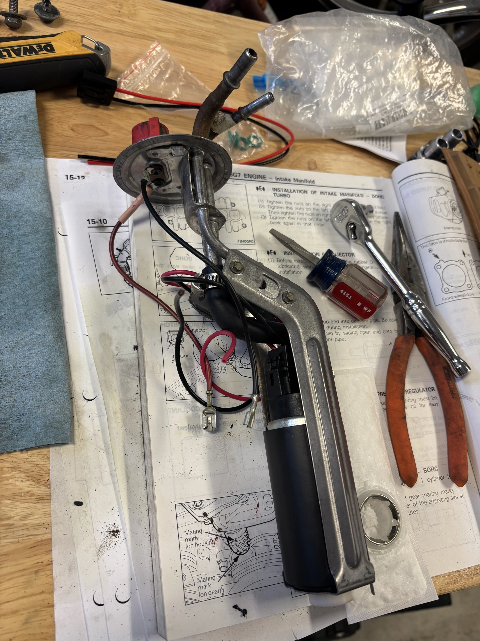
Ok so I received my new fuel gauge sending unit, filter, & fuel pump hanger rebuild kit today. Installation was super easy! I went to turn ignition to ON to test the pump, and no pump priming sound. I spent the next three hours troubleshooting. I have 12v at the fuel pump relay u set my drivers seat, 12v at the enertia switch in the trunk, but only 8v at the harness connection where the wires plug in to go to the fuel pump and fuel gauge sending unit. What could be causing this drop in voltage?
Attachments
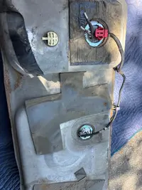
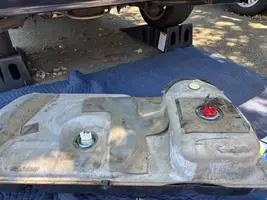


Ok looking at the two diagrams above, it appears that the FP Relay is wired and receives power from the Fuel Inertia Switch (Red/Blk) AND from Wire 22 (Tan/Grn) on the EEC. From the FP Relay, the fuel pump receives power.
Here are the voltage readings I'm seeing at the connected Fuel Pump Relay:
- Wire #37 (VPWR) - Switched Power = 0v w/Ignition OFF and 12.5v w/Ignition ON
- Wire #1 (KAPWR) - Constant Power = 12.8v w/Ignition OFF and 12.35 w/Ignition ON
- Wire #22 (FP) = 0v w/Ignition OFF and 12.5v w/Ignition ON
- Wire #19 (FPM = 0v w/Ignition OFF and 12.5v w/Ignition ON for a second or two, then the relay clicks and voltage measured .22v

Wire #1 - Constant 12V+ from battery to EEC relay and fuel pump relay.
Wire #19 - When key is on and ECU commands the pump to run this wire provides 12V+ to the fuel pump and to the ECU. Its provides 12V+ to the ECU so the ECU knows the pump has 12V+ and should be running.
Wire #22 - This wire is a ground from the ECU to the fuel pump relay. This how the ECU commands the fuel pump to run. The same wire also goes to the self-test connector in the engine bay on the driver side near the brake master cylinder. This is so that when you plug in the code reader it can test the relay. You can also put a ground to this wire and force the pump to run with the key in the "run" position.
Wire #37/57 - This wire is 12V+ from the ECU to the fuel pump inertia switch and then to the fuel pump relay coil. When the ECU provides a ground (Wire #22) to the other side of the coil then Wire #19 from the fuel pump relay provides 12V+ to the fuel pump and a run signal to the ECU.
With all of that you should not be seeing 12V+ on Wire #22 as this is the wire that grounds the coil in the fuel pump relay which comes from the ECU.
Wire #19 - When key is on and ECU commands the pump to run this wire provides 12V+ to the fuel pump and to the ECU. Its provides 12V+ to the ECU so the ECU knows the pump has 12V+ and should be running.
Wire #22 - This wire is a ground from the ECU to the fuel pump relay. This how the ECU commands the fuel pump to run. The same wire also goes to the self-test connector in the engine bay on the driver side near the brake master cylinder. This is so that when you plug in the code reader it can test the relay. You can also put a ground to this wire and force the pump to run with the key in the "run" position.
Wire #37/57 - This wire is 12V+ from the ECU to the fuel pump inertia switch and then to the fuel pump relay coil. When the ECU provides a ground (Wire #22) to the other side of the coil then Wire #19 from the fuel pump relay provides 12V+ to the fuel pump and a run signal to the ECU.
With all of that you should not be seeing 12V+ on Wire #22 as this is the wire that grounds the coil in the fuel pump relay which comes from the ECU.

BTW - This is a great post and content for anyone that is having fuel pump / pressure issues:

I followed this procedure and found that my new pump is being supplied 12.5v and is not running. I need to drop the tank again and troubleshoot the new pump I just installed. Yes - I should have bench tested my brand new pump to make sure it was working - It likely would have saved me this re-work. What can I say, I assumed the new pump would work - I'm not a professional...
Electrical Thread 'Fuel pump relay wiring'
Just need to double check this...
On the fuel pump relay under the seat, the pink/black wire is the ground? and the red/black wire the power?
Finishing up the 4.6 swap and the only electrical thing left is to wire in the fuel pump. I've found the 2 wires coming from the 4.6 ECU that I need to splice into... one to send the ground the fuel pump, and the other to provide fuel pump power. So the pink/black for ground and red/black for power?
The vague instructions I was reading said to splice into the dark green/yellow wire at the inertia switch for power...
On the fuel pump relay under the seat, the pink/black wire is the ground? and the red/black wire the power?
Finishing up the 4.6 swap and the only electrical thing left is to wire in the fuel pump. I've found the 2 wires coming from the 4.6 ECU that I need to splice into... one to send the ground the fuel pump, and the other to provide fuel pump power. So the pink/black for ground and red/black for power?
The vague instructions I was reading said to splice into the dark green/yellow wire at the inertia switch for power...
- africansnowowl
- Replies: 2
- Forum: Fox 5.0 Mustang Tech
I followed this procedure and found that my new pump is being supplied 12.5v and is not running. I need to drop the tank again and troubleshoot the new pump I just installed. Yes - I should have bench tested my brand new pump to make sure it was working - It likely would have saved me this re-work. What can I say, I assumed the new pump would work - I'm not a professional...
Hey AeroCoupe - Really appreciate your post and the specific detail you've provided - Very helpful.Wire #1 - Constant 12V+ from battery to EEC relay and fuel pump relay.
Wire #19 - When key is on and ECU commands the pump to run this wire provides 12V+ to the fuel pump and to the ECU. Its provides 12V+ to the ECU so the ECU knows the pump has 12V+ and should be running.
Wire #22 - This wire is a ground from the ECU to the fuel pump relay. This how the ECU commands the fuel pump to run. The same wire also goes to the self-test connector in the engine bay on the driver side near the brake master cylinder. This is so that when you plug in the code reader it can test the relay. You can also put a ground to this wire and force the pump to run with the key in the "run" position.
Wire #37/57 - This wire is 12V+ from the ECU to the fuel pump inertia switch and then to the fuel pump relay coil. When the ECU provides a ground (Wire #22) to the other side of the coil then Wire #19 from the fuel pump relay provides 12V+ to the fuel pump and a run signal to the ECU.
With all of that you should not be seeing 12V+ on Wire #22 as this is the wire that grounds the coil in the fuel pump relay which comes from the ECU.
I actually ran the ground test on the "self-test" connector and can see that when I make this connection I hear the fuel pump relay fire (click) and have 12.5v at the fuel tank harness at the rear of the tank. When I plug in the fuel pump / sending unit connector to the tank harness I also hear clicking in the tank when I ground the "self-test" connector but the pump does not run. My next step is to drop the tank again and pull the fuel hanger again to test the new pump.
All the test I ran yesterday were with the fuel pump relay plugged-in. When I tested Wire #19 (FPM = 0v w/Ignition OFF and 12.5v w/Ignition ON for a second or two, then the relay clicks and voltage measured .22v. Does this sound like it is functioning correctly? I understand that normally the fuel pump is supposed to fire briefly to pressurize the system and then turn off. The amount of time the pump fires / runs to charge the fuel system is typically about a second, maybe two - I read this is a set amount of time by the computer. Once the engine starts to turn over the computer senses this, the computer completes the ground for the pump to continuously to run. Please let me know if you have any insights or thoughts - Ciao!
Hell, a pro likely wouldn't bench test it either......Yes - I should have bench tested my brand new pump to make sure it was working - It likely would have saved me this re-work. What can I say, I assumed the new pump would work - I'm not a professional...
That is correct. There is an initial 2-3 second fuel pump prime when the key is put in the “run” position. Then when the key is put in the “crank” position the ECU detects this via the distributor and turns the pump on.
If you applied a ground to wire #22 at the test connector and you heard the relay click and have 12V+ at the connector at the rear of the car then the pump should run as long as it was wired correctly and is a know good pump.
It’s still concerning that the #22 wire showed 12V+ which could be an indication of the ECU having an issue. Check the pump first and get that sorted and working. When you get it running off grounding the #22 wire in the self test connector try it with the ECU.
If you applied a ground to wire #22 at the test connector and you heard the relay click and have 12V+ at the connector at the rear of the car then the pump should run as long as it was wired correctly and is a know good pump.
It’s still concerning that the #22 wire showed 12V+ which could be an indication of the ECU having an issue. Check the pump first and get that sorted and working. When you get it running off grounding the #22 wire in the self test connector try it with the ECU.
Last edited:
Ok, so I'm not going to be one of the members that ghost's their post once they find the solution to their problem, no matter how embarrassing the problem was that ended up being the root cause.
So, after pulling the tank (again) and the fuel-pump hanger, I put 12v to the +/- terminals - Nothing! Looking closer at the pump I noticed that new fuel pump wire harness was not fully seated into the pump! I had pushed it into the pump, but clearly not hard enough - Once I fully seated the plug - I tested w/ 12v and Valla ~ The pump engaged!
Ok, I'm an idiot and must have worked too fast to notice my mistake...
So, after pulling the tank (again) and the fuel-pump hanger, I put 12v to the +/- terminals - Nothing! Looking closer at the pump I noticed that new fuel pump wire harness was not fully seated into the pump! I had pushed it into the pump, but clearly not hard enough - Once I fully seated the plug - I tested w/ 12v and Valla ~ The pump engaged!
Ok, I'm an idiot and must have worked too fast to notice my mistake...

gkomo
now i can hopefully expect to receive the shaft

So, this one guy I know ( me  ) was in such a hurry one time that he left a combo wrench on one of the cam bolts when he cranked it over a brand new engine.
I'd like to go back and kick that dude's ass.
) was in such a hurry one time that he left a combo wrench on one of the cam bolts when he cranked it over a brand new engine. I'd like to go back and kick that dude's ass.

When I was about 20yrs old and working under a journeyman mechanic I dropped a deep well socket down the distributor hole of a 390 truck engine. Man I was an idiot. The mechanic told me to listen carefully as he hopped in the cab and bumped the starter ever so briefly. I heard a dull thunk. He said, “did you hear that”? I said, “yes”. He said, “that was the socket hitting the bottom of the oil pan, and thats where it’s gonna stay”. The socket was left in there and it never caused a problem as long as I worked there.

Left a socket and breaker bar on the crank bolt once, you only do that once! It was exciting for a second.

Mcmahst
5 Year Member

That's why I don't have a wife anymore.
she always said I was an idiot.......I didn't believe her and I ain't gonna tell her she was right!
she always said I was an idiot.......I didn't believe her and I ain't gonna tell her she was right!
Similar threads
- Replies
- 0
- Views
- 156

- Replies
- 11
- Views
- 484

- Replies
- 4
- Views
- 414

- Replies
- 6
- Views
- 379