It's one of the simpler mods you can do.
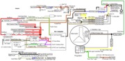
Aside from adding the 4 gauge power wire, you cut white/black wire and splice another to it. Solder & heat shrink the splice, then add a 1/4" female slip connector and the wiring part is done. Here's websites with pictures of the 3G installation...
See
http://www.geocities.com/smithmonte/Auto/3G_130A_Alternator_Upgrade.htm - all the tech data you could ever want to know
OR
http://www.mustangcentral.net/tech/alternator.html - excellent pictures of installation
Use these sites for information on the right way to do the wiring. Some people will tell you that you can skip the wiring upgrade, but it will catch up with you sooner or later. A fire in the wiring harness is ugly and expensive.
Under no circumstances connect the two 10 gauge black/white wires to the 3G alternator. If the fuse blows in the 4 gauge wire, the two 10 gauge wires will be overloaded to the point of catching fire and burning up the wiring harness.
The secondary power ground is between the back of the intake manifold and the driver's side firewall. It is often missing or loose. It supplies ground for the alternator, A/C compressor clutch and other electrical accessories such as the gauges.
Any car that has a 3G alternator needs a 4 gauge ground wire running from the block to the chassis ground where the battery pigtail ground connects.
Electric fan = 3G alternator if you want long life & reliability from your car.
The electric fan saves some HP. The stock fan's parasitic drag runs from 7-12 HP depending on who you talk to. The electric fan uses about 1/2 HP of power from the electrical system.
See
WWW.partsexpress.com for the fuse & fuse holder.
Fuse @ $3.90 each (need one)
http://www.partsexpress.com/pe/showdetl.cfm?&DID=7&Partnumber=071-952
Fuseholder @ $5.80 each (need one)
http://www.partsexpress.com/pe/showdetl.cfm?&DID=7&Partnumber=263-630
4 gauge black wire @ $1.25 a foot (use string to lay out routing & determine length)
http://www.partsexpress.com/pe/showdetl.cfm?&DID=7&Partnumber=100-196
4 gauge red wire @ $1.25 a foot (use string to lay out routing & determine length)
http://www.partsexpress.com/pe/showdetl.cfm?&DID=7&Partnumber=100-194
4 gauge ring crimp terminals (package of 5) $3.25.
http://www.partsexpress.com/pe/showdetl.cfm?&DID=7&Partnumber=095-584
3/4 “ Black heat shrink tubing, 4ft length, $3.39
http://www.partsexpress.com/pe/pshow...number=082-058
3/4 “ Red heat shrink tubing, 4ft length, $3.39
http://www.partsexpress.com/pe/pshow...number=082-064
Pre-fab 4 gauge cables with lugs already on the ends are available in most auto parts stores. Look for the starter switch to starter cables.
I am very careful to maintain backwards compatibility, so I did things a little different. The white/black stator wire gets the insulation stripped back about 1 1/2" in the middle of the wire & cut in the middle of the stripped area. Then a short length of white wire with a 1/4" slip on female spade connector gets spliced on to the white/black wire. Slide on enough 1/4" heat shrink tubing on the white wire to cover the solder splice you are going to make. Next all 3 wires get soldered together & the heat shrink tubing gets shrunk. When you finish, the white/black wire looks like a "Y" with 1 white arm and 1 white/black arm. I left the black/orange wires connected to the original plug and did not do anything to them. When you are done, the original plug still has all the wires connected to it and they are still functional. The extra white pigtail wire that you spliced, soldered in & covered with heat shrink tubing is just long enough to plug into the 3G without much left over.
I ran the 4 gauge wire under the front of the engine next to the 4 gauge wire for the starter power feed.
It came up the same path as the fuel injector supply lines, and gets bolted to the power output lug of the 3G alternator. The 125 amp fuse is mounted on a plastic panel bolted to the stock ignition coil mounts. One of side of the fuse has a 4 gauge wire connected to the battery side of the starter solenoid & the other to the 4 gauge power feed wire for the alternator.
I had some 1" silicone aircraft heat shield tubing that I fed the 4 gauge alternator power feed wire through and tie wrapped & clamped it in place with some aircraft cushion clamps. That provided the wire extra protection from road debris and rocks. Some heater hose could be used to do the same thing.
Apart from the grinding I did on the mount bracket, there wasn't much to it. Rather than just grind a notch, I ground the whole web back to the thick part of the bracket. It looks much more factory that way.