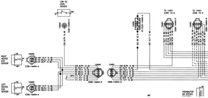
Ok, couple weeks ago my o2 harness got shredded, snagged a root or a rock or something in the yard, anyway it was fubar, and now ive been driving my crap for a couple weeks with no o2's and im tired of getting 15mpg. SO!
I have a connector that will go to the main harness but thats it, i want to make my own harness to each bank o2 sensor.
So does anybody have a diagram of what pins go where on the connector, or which side bank specificly would be veddy helpful, i dont have anything to do tomorrow and i need to get it done..
I have a connector that will go to the main harness but thats it, i want to make my own harness to each bank o2 sensor.
So does anybody have a diagram of what pins go where on the connector, or which side bank specificly would be veddy helpful, i dont have anything to do tomorrow and i need to get it done..