Use the paper clip - it sometimes works when code readers won't.
Dump the codes and see what the computer says is wrong…Codes may be present in the computer
even if the Check Engine light isn’t on.
Here's the link to dump the computer codes with only a jumper wire or paper clip and the check
engine light, or test light or voltmeter. I’ve used it for years, and it works great.
See
http://www.troublecodes.net/Ford/
IF your car is an 86-88 stang, you'll have to use the test lamp or voltmeter method. There is no
functional check engine light on the 86-88's except possibly the Cali Mass Air cars.
Codes have different answers if the engine is running from the answers that it has when the engine
isn't running. It helps a lot to know if you had the engine running when you ran the test.
Trouble codes are either 2 digit or 3 digit, there are no cars that use both 2 digit codes and 3 digit codes.
For those who are intimidated by all the wires & connections, see
http://www.actron.com/product_detail.php?pid=16153
for what a typical hand scanner looks like. Normal retail price is about $30 or so at AutoZone or Wal-Mart.
Or for a nicer scanner see
http://www.midwayautosupply.com/pc-7208-90-equus-digital-ford-code-reader-3145.aspx
– It has a 3 digit LCD display so that you don’t have to count flashes or beeps.. Cost is $30.
If the paperclip doesn't work , you probably have some wiring problems that are also affecting the
critical sensors like the TPS, BARO/MAP, ECT and ACT.
Computer will not go into diagnostic mode
How it is supposed to work:
The black/white wire (pin 46) is signal ground for the computer. It provides a dedicated
ground for the EGR, Baro, ACT, ECT, & TPS sensors as well as the ground to put the
computer into self test mode.
If this ground is bad, none of the sensors mentioned will work
properly. That will severely affect the car's performance. Since it is a dedicated ground,
it passes through the computer on its way to the computer main power ground that terminates at the
battery pigtail ground. It should read less than 1.5 ohms when measured from anyplace on the
engine harness with the battery pigtail ground as the other reference point for the ohmmeter probe.
What sometimes happens is that it gets jumpered to power which either burns up the wiring or
burns the trace off the pc board inside the computer. That trace connects pins 46 to pins 40 & 60.
Only an experienced electronics technician can open the computer up & repair the trace if it burns
up and creates an open circuit.
The STI (Self Test Input ) is jumpered to ground to put the computer into test mode. Jumpering
it to power can produce unknown results, including damage to the computer. The ohm test
simply verifies that there are no breaks in the wiring between the test connector and the computer input.
How to test the wiring :
With the power off, measure the resistance between the computer test ground
(black/white wire) on the self test connector and battery ground. You should see less than
1.5 ohms.
If that check fails, remove the passenger side kick panel and disconnect the computer
connector. There is a 10 MM bolt that holds it in place. Measure the resistance between
the black/white wire and pin 46: it should be less than 1.5 ohms. More that 1.5 ohms is a
wiring problem. If it reads 1.5 ohms or less, then the computer is suspect. On the
computer, measure the resistance between pin 46 and pins 40 & 60: it should be less than
1.5 ohms. More that that and the computer’s internal ground has failed, and the computer
needs to be replaced.
If the first ground check was good, there are other wires to check. Measure the
resistance between the STI computer self test connector (red/white wire) and pin 48 on
the computer main connector: it should be less than 1.5 ohms. More that 1.5 ohms is a
wiring problem
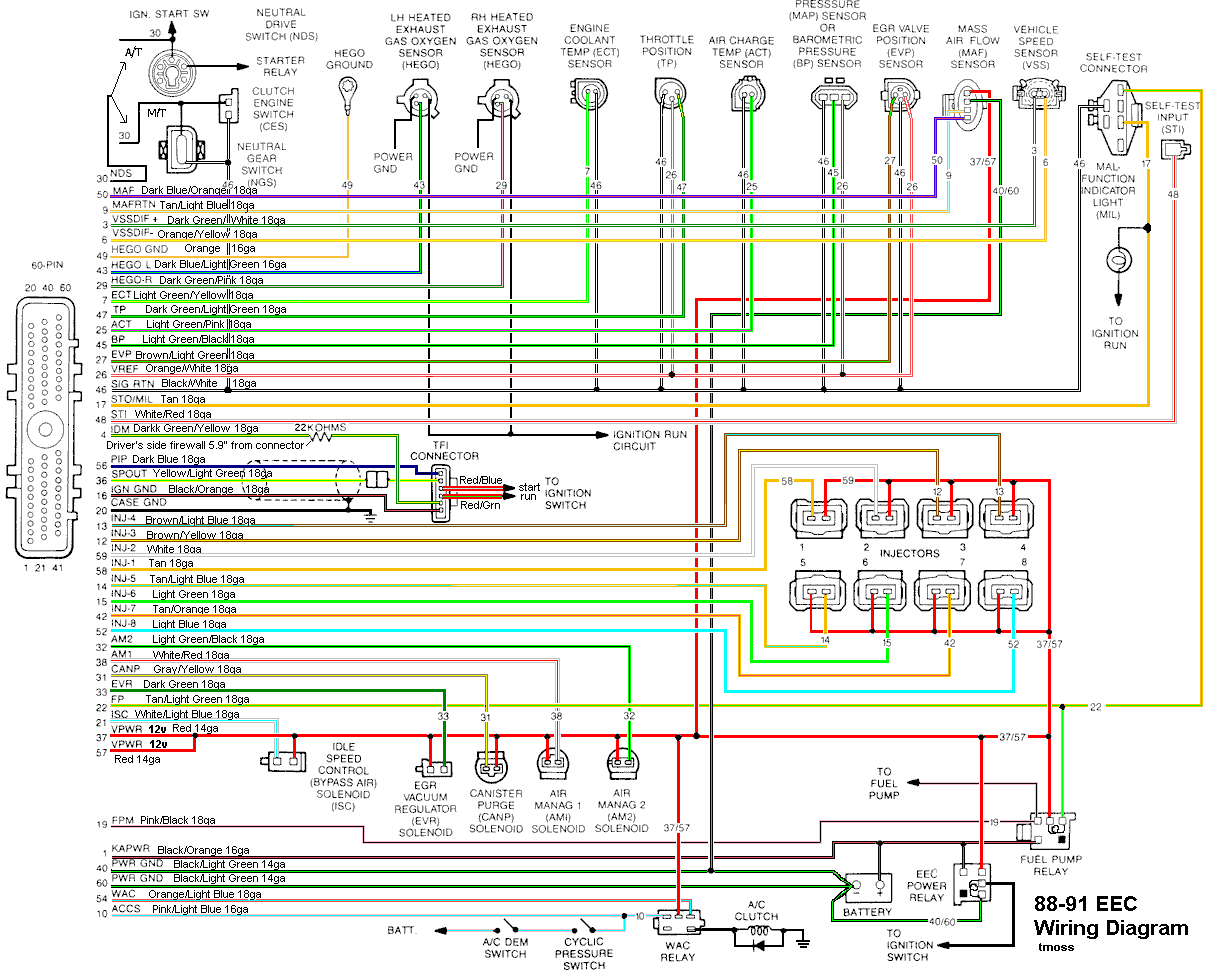
The following is a view from the computer side of the computer connector.
Diagram courtesy of Tmoss & Stang&2birds
See the following website for some help from Tmoss (diagram designer) & Stang&2Birds
(website host) for help on 88-95 wiring
http://www.veryuseful.com/mustang/tech/engine


 As far as codes im not getting a engine light, I have tried reading my codes before and it says cannot read the computer. ( I have reading my mustang " start the car ,turn the car off, start it , turn the wheel , rev it up ect.) The car is a 1990 so it already has mass air the only thing I can think of is that I replaced 2 injectors from an 86 mustang but think there the same thing as the 90