Good troubleshooting takes time. Everyone seems to be looking for
the magic tip that says replace this $13 part and your problems are
cured. You don't have to think, dig or diagnose, just buy the part and
install it. Unfortunately, it doesn’t work that way 99% of the time.
Thinking is hard work and educated thinking requires much more
effort than simple parts swapping. The complexity and age of these
5.0 Mustangs works against that, as well as the number of hands
that have “modified” the original design. Sometimes that
modification is well done with good workmanship and other times it
is mechanical road kill. It is very easy to become the victim of the
previous owner’s efforts.
I spend a great deal of time trying to communicate the methodology
of structured troubleshooting principles. For those who haven’t been
beat with this stick before, here they are again:
1.) Understand the system. That involves reading some books to get
an overall picture of how it works. For 5.0 Mustangs, that list starts
with the Chilton shop manual and the Probst book, Ford Fuel
Injection & Electronic Engine Control 1988-1993 by Charles
Probst :ISBN 0-8376-0301-3. It's about $20 from Borders.com, see
http://www.amazon.com. Select books and then select
search. Use the ISBN number (without dashes or spaces) to do a
search. Use the ISBN number and your local library can get you a
loaner copy for free for 2 weeks or so. Another resource is the
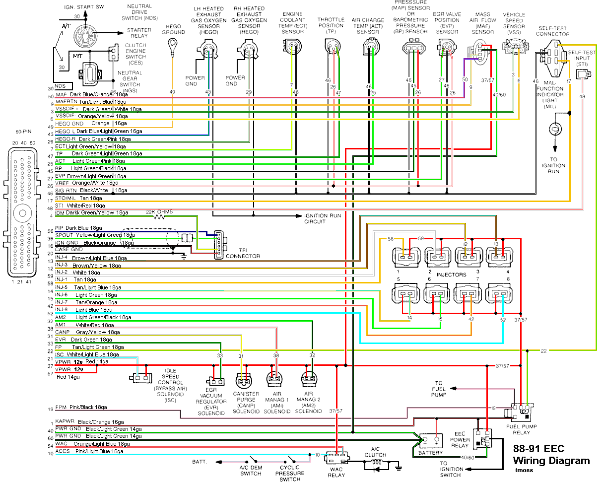
following website by Tmoss (diagram designer) & Stang&2Birds
(website host) for help on 88-95 wiring:
http://www.veryuseful.com/mustang/tech/engine. Study
the diagrams and tech articles. There is an amazing amount of good
stuff in one place for FREE.
2.) Isolate the problem. You need to be able to break the system
down into functional blocks or subsystems. Once you know what
subsystem has failed, it is much easier to troubleshoot. Group
problem symptoms according to what system controls them. Don’t
look for a fix for ignition problems by adjusting the fuel pressure.
Have an organized, step by step, approach to work your way through
a subsystem and check its functions. Work all the way through a
subsystem before you quit and go off wildly chasing rabbits. You
have three tools to use in your efforts:
measure, meter and
observe. Use these three tools to narrow down the list of possible
failure points into a small, easily managed list of items.
3.) Install the fix. .Now that you have a short list of suspected
villains, plan your repair efforts so that you do the easy things first.
If an item from the easy list didn’t fix your problem, then look at the
high failure rate items. Spend some time here on Stangnet and you’ll
get an idea of what the most commonly replaced parts are, things
like TFI modules, ignition switches and fuel pumps.
If you make a change and it doesn’t relieve the problem symptoms,
put it back the way it was. I have a stack of parts from where I
swapped a part and it didn’t fix the problem. I put the old part back
on the car and the new part went on the shelf. Someday I will either
use them or trade them for something else.
The Cranks OK, but No Start Checklist for Fuel Injected Mustangs is
the basic place to start since it encompasses the principles stated
above.
1.) Remove push on connector from starter solenoid and turn ignition
switch on. Place car in neutral or Park. Remove coil wire from
distributor & and hold 3/8” away from engine block. Jumper the
screw to the big bolt on the starter solenoid that has the battery wire
connected to it. You should get a nice fat blue spark.
Most of the items are electrical in nature, so a test light, or even
better, a voltmeter, is helpful to be sure they have power to them.
No spark, possible failed items in order of their probability:
A.) MSD or Crane ignition box if so equipped
B.) Coil
C.) TFI module
D.) PIP sensor in distributor
E.) ECC relay next to computer - look for 12 volts at the fuel injector red wires
F.) Fuse links in wiring harness - look for 12 volts at the fuel injector red wires.
All the fuse links live in a bundle up near the starter solenoid.
G.) Ignition switch - look for 12 volts at the ignition coil red/lt green wire.
H.) Computer
See the following links for wiring diagrams...
http://www.autozone.com/servlet/UiB..._us/0900823d/80/16/71/3c/0900823d8016713c.jsp for 79-88 model cars
Computer/fuel pump/ignition wiring diagram, 86 model
http://www.autozone.com/images/cds/gif/large/0900823d80167158.gif
Computer/fuel pump/ignition wiring diagram, 87 model
http://www.autozone.com/images/cds/gif/large/0900823d8016715e.gif
Computer/fuel pump/ignition wiring diagram, 88 model
http://www.autozone.com/images/cds/gif/large/0900823d80167162.gif
http://www.autozone.com/servlet/UiB..._us/0900823d/80/19/59/5a/0900823d8019595a.jsp for 89-93 model cars
Computer/fuel pump/ignition wiring diagram, 89-90 cars
http://www.autozone.com/images/cds/gif/large/0900823d8019595f.gif
Computer/fuel pump/ignition wiring diagram, 91-93 cars
http://www.autozone.com/images/cds/gif/large/0900823d80195960.gif
http://www.autozone.com/servlet/UiB..._us/0900823d/80/1d/db/3c/0900823d801ddb3c.jsp for 94-98 model cars
2.) Spark at coil wire, pull #1 plug wire off at the spark plug and
check to see spark. No spark, possible failed items in order of their
probability:
A.) Moisture inside distributor – remove cap, dry off & spray with WD40
B.) Distributor cap
C.) Rotor
D.) Spark Plug wires
E.) Coil weak or intermittent - you should see 3/8" fat blue spark with a good coil
3.) Spark at spark plug, but no start.
Next, get a can of starting fluid (ether) from your local auto parts
store: costs a $1.30 or so. Then pull the air duct off at the throttle
body elbow, open the throttle, and spray the ether in it. Reconnect
the air duct and try to start the car. Do not try to start the car
without reconnecting the air duct.
Two reasons:
1.) If it backfires, the chance for a serious fire is increased.
2.) On Mass Air cars, the computer needs to measure the MAF flow
once the engine starts.
If it starts then, you have a fuel management issue. Continue the
checklist with emphasis of fuel related items that follow. If it doesn’t,
then it is a computer or timing issue: see Step 4.
Clue – listen for the fuel pump to prime when you first turn the
ignition switch on. It should run for 5-20 seconds and shut off. To
trick the fuel pump into running, find the ECC test connector and
jump the connector in the Upper RH corner to ground.
If the relay & inertia switch are OK, you will have power to the
pump. Check fuel pressure – remove the cap from the schrader valve
behind the alternator and depress the core. Fuel should squirt out,
catch it in a rag. Beware of fire hazard when you do this. In pinch
you can use a tire pressure gauge to measure the fuel pressure. It
may not be completely accurate, but you will have some clue as to
how much pressure you have.
No fuel pressure, possible failed items in order of their probability:
A.) Tripped inertia switch – Coupe & hatch cars hide it under the
plastic trim covering the driver's side taillight. Use the voltmeter or
test light to make sure you have power to both sides of the switch
B.) Fuel pump power relay – located under the driver’s seat in most
stangs built before 92. On 92 and later model cars it is located below
the Mass Air Flow meter. Look for 12 volts at the Pink/Black wire on
the fuel pump relay.
C.) Clogged fuel filter
D.) Failed fuel pump
E.) Blown fuse link in wiring harness. Look for 12 volts at the
Orange/Lt Blue wire on the fuel pump relay. The fuse links live in the
wiring harness near the starter solenoid.
F.) Fuel pressure regulator failed. Remove the vacuum line from the
regulator and inspect for fuel escaping while the pump is running.
Fuel pressure OK, the injectors are not firing.
A.) A Noid light available from Autozone, is one way to test the injector wiring.
B.) I like to use an old injector with compressed air applied to the
injector where the fuel rail would normally connect. I hook the whole
thing up, apply compressed air to the injector and stick it in a paper
cup of soapy water. When the engine cranks with the ignition switch
on, if the injector fires, it makes bubbles. Cheap if you have the stuff
laying around, and works good too.
a.) Pull an injector wire connector off and look for 12 volts on the red
wire when the ignition switch is on.
b.) No power, then look for problems with the 10 pin connecter (salt
& pepper shakers at the rear of the upper manifold).
c.) No power and the 10 pin connections are good: look for broken
wiring between the orange/black wire on the ECC relay and the red
wire for the 10 pin connectors.
4.) Spark & fuel pressure OK.
A.) Failed IAB (no airflow to start engine). Press the throttle ¼ way
down and try to start the car.
B.) Failed computer (not very likely)
C.) Engine ignition or cam timing off: only likely if the engine has
been worked on recently).
D.) Firing order off: HO & 351 use a different firing order from the
non HO engines.
HO & 351W 1-3-7-2-6-5-4-8
Non HO 1-5-4-2-6-3-7-8
E.) No start when hot - Press the throttle to the floor & try starting it
if you get this far. If it starts, replace the ECT.
Specific areas for hot start problems:
Check spark when hot – no spark, possible failure items are TFI
module, coil and PIP sensor in the distributor. Note that a failed PIP
sensor will also cause the injectors not to fire.
Check fuel pressure when hot – no fuel pressure/low fuel pressure,
possible failure items are fuel pump, fuel pump wiring, fuel pump
relay. The wiring inside the tank at the pump itself is suspect, since
it is subject to moisture in the fuel. The moisture can cause corrosion
and poor connections.
Fuel pressure OK, spark OK - either you have an excess of fuel or
shortage of fuel. Pulling a spark plug and doing a sniff test will help
here: smell fuel and you know that the fuel delivery system is
working more than it should. Possible suspects are the ECT, ACT, and
leaking injectors.
Fuel pressure OK, the injectors are not firing, OR one or more
injectors stuck open
Do a cylinder balance test: Warm the car's engine up to normal
operating temperature. With the Engine Off, Key OFF, use a jumper
wire or paper clip to put the computer into test mode. Here's the link
to dump the computer codes with only a jumper wire or paper clip
and the check engine light, or test light or voltmeter. You’ll need it to
do the cylinder balance test
See
http://www.troublecodes.net/Ford/
OR
See
http://www.dalidesign.com/hbook/eectest.html for more descriptive help
OR
See
http://www.mustangworks.com/articles/electronics/eec-iv_codes.html
Start the engine and let it go through the normal diagnostic tests,
then quickly press the throttle to the floor. The engine RPM should
exceed 2500 RPM's for a brief second. The engine will shut off power
to each injector, one at a time. When it has sequenced through all 8
injectors, it will flash 99 or the number of the failing cylinder such as
22 for cylinder #2. Quickly pressing the throttle again up to 2500
RPM’s will cause the test to re-run with smaller qualifying figures. Do
it a third time, and if the same cylinder shows up, the cylinder is
weak and isn’t putting out power like it should. See the Chilton’s
Shop manual for the complete test procedure.
The red wire on each injector is powered up whenever the ignition
switch is in the Run position. The computer provides a ground to
complete the circuit and fire the injector. The injector
must
have a ground to squirt fuel on command. A short to ground in the
injector return wiring can cause one or more injectors to be
continually open or triggered
A.) A Noid light available from Autozone, is one way to
test the injector wiring. If the light stays on constantly, either the
wiring has a short to ground or the computer has failed
B.) I like to use an old injector with compressed air applied to
the injector where the fuel rail would normally connect. I hook the
whole thing up, apply compressed air to the injector and stick it in a
paper cup of soapy water. When the engine cranks with the ignition
switch on, if the injector fires, it makes bubbles An injector stuck
open will release a continual stream of bubbles. Cheap if you have
the stuff laying around, and works good too. The same trick works
great to find leaking injectors too.
The wiring for the injectors may have some bare spots in it causing
the injector to computer control wire to ground out. This would cause
the injector to remain on anytime the key was in the Run position.
Remove the injector wiring connectors from the injector. Note that
each injector has one red wire for power and a non red wire (wire
some color other than red) for computer controlled ground. With the
key off, disconnect the computer connector from the computer. Use
an Ohmmeter between the non red wire and ground. You should see
more than 100000 (100K) ohms resistance.
See the following website for some help from Tmoss (diagram
designer) & Stang&2Birds (website host) for help
Using the above diagram, check the resistance between the injector
and the computer. Clean and check the 10 pin connectors since they
are a potential trouble source. Any resistance greater than 1 ohm
between the injector to computer wire and the matching pin on the
computer connector is a problem.
See
http://fordfuelinjection.com/?p=6 for more help
ECT and Act problems: Dumping the codes as described above will
spot most of the ECT & ACT problems. Here’s the data to test the
sensors if you suspect them.
Code 21 – ECT sensor out of range. Broken or damaged wiring, bad
ECT sensor.
Note that that if the outside air temp is below 50
degrees F that the test for the ECT can be in error.
The ECT sensor has absolutely nothing to do with the temperature
gauge. They are different animals. The ECT sensor is normally
located it the RH front of the engine in the water feed tubes for the
heater.
The ACT & ECT have the same thermistor, so the table values are the same
ACT & ECT test data:
Use Pin 46 on the computer for ground for both ECT & ACT to get
most accurate readings.
Pin 7 on the computer - ECT signal in. at 176 degrees F it should be .80 volts
Pin 25 on the computer - ACT signal in. at 50 degrees F it should be
3.5 volts. It is a good number if the ACT is mounted in the inlet
airbox. If it is mounted in the lower intake manifold, the voltage
readings will be lower because of the heat transfer.
Voltages may be measured across the ECT/ACT by probing the
connector from the rear. Use care in doing it so that you don't
damage the wiring or connector.
Here's the table :
68 degrees F = 3.02 v
86 degrees F = 2.62 v
104 degrees F = 2.16 v
122 degrees F = 1.72 v
140 degrees F = 1.35 v
158 degrees F = 1.04 v
176 degrees F = .80 v
194 degrees F = .61
Note that all resistance tests must be done with power off.
Measuring resistance with a circuit powered on will give false
readings and possibly damage the meter.
Ohms measures at the computer with the computer disconnected, or
at the sensor with the sensor disconnected.
50 degrees F = 58.75 K ohms
68 degrees F = 37.30 K ohms
86 degrees F = 27.27 K ohms
104 degrees F = 16.15 K ohms
122 degrees F = 10.97 K ohms
140 degrees F = 7.60 K ohms
158 degrees F = 5.37 K ohms
176 degrees F = 3.84 K ohms
194 degrees F = 2.80 K ohms