Painless universal kit install (update)

Edbert

Founding Member
Jul 13, 2002
3,548
32
109
Austin TX
Well, the huge thread with a lot of the tech got wiped by the server crash but here it is in a nutshell. I changed my mind for about the twentieth time and chose to do the install myself despite my wife's approval to spend $2,000.00 and have a professional do it. I made that call largely to the encouragement from folks here. The last time I got a day to work on it I started by pulling all the wires back out of the car and re-routing them through a different area of the back seat divider, it turns out the top would rub on the conduit when it was in the retracted (down) position. But after doing that we were able to figure out all of the switches and get the main power and ground sources all worked out.

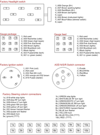
This coming Staurday my goal is to have the harness all connected except for lights. I am connecting all of the switches without trimming any wires to length, once I am sure everything works correctly I intend to cut each wire and route it through the conduit, then solder all the connections. Anyhow, I thought I'd post this drawing. My friend was able to figure all of these connections out using a battery powered multi-meter (don't ask me how, cause it looked like voodoo to me).

switch_connections.jpg


During the process I am taking lots of pictures and will have a full write-up completed. Should make it easy for anyone else trying to do what I am doing. Here's the page as it stands:
http://www.edbert.net/painless.htm

The drawing for the engine compartment has been revised significantly so please ignore that one for now, I'll post the changes this week.
 
Cool Ed! I just unwrapped my engine wire harness last night to find that a wire had melted the insulation off from the solenoid to the firewall. :( I've got some work to do too, and I think your info is going to be a big help. :)
 
Good luck. I have plans for a EZ-Wiring 21 kit. Its not a direct replacement for my 69 of course. But for oh $160 i believe its well worth it. Now the fun of putting it in and getting everything wired is another story. Fortunetly im not alone in this battle, my uncle and father are going to be there to help me. Let us know what if any problems you run into.
 
Edbert said:
Did you check out my painless page?
http://www.edbert.net/painless.htm
I've got some other drawings there that might help you out.

I just got done reading it and it is great. However I don't intend on using that many relays and I also bought the EZWiring kit. Your diagrams for the switches really are helpful. I was most worried about getting those right and you cleared a lot of it up for me thanks!!! :nice:
 
Hey edbert. Your huge diagram on the website still has your relays drawn backwards.

I know I explained it before the big server crash, but here it is again.

You want your hot from the fuse block for the device going to pin 30, you want some power from your "terminal" going through a switch to pin 85. Pin 86 connected to ground. Finaly pin 87A will go to your device. (pins 85 and 86 are interchanagable for connection to ground)

Like I said before, how you have them drawn will allow the device to run but its not operationg the relay the way it is ment to operate. It will also cause a constant power drain as your relays will always be energized; even with the key off.
 
LOL, you got to me before I could fix it. Here's the new drawing:

engcompwiring2.webp


This drawing is also a work in progess so all disclaimers apply :D

You'll notice I also added a second terminal block, one if full amp B+ the other is keyed to the ignition switch. When I turn the key from run to start everything will stop except the starter, but that's okay with me.
 

Attachments

  • engcompwiring2.webp
    engcompwiring2.webp
    82.1 KB · Views: 109
Just to confirm...

I received advice that the switch for my thermostatic sensor (on/off switch) should be connected to pin 85. So I decided to keep that pattern for the others. I also standardized on using pin 30 for all of the "loads".

Do I still have it wrong?
 
Edbert said:
Just to confirm...

I received advice that the switch for my thermostatic sensor (on/off switch) should be connected to pin 85. So I decided to keep that pattern for the others. I also standardized on using pin 30 for all of the "loads".

Do I still have it wrong?

No, its good to standardize for your own sanity down the road. pins 85 and 86 are interchangeable. In this application pins 30 and 87 are also interchangable, but for standardization sake pin 30 going to all the loads its a good idea.

You really have gone relay crazy. Your painless harness should have circuits built into it for most of these things..and the 2 relays for the headlights are most definately just a waste of a relay.
 
also,

You should only need relays for the curcuits that:

a) dont exist on the wiring harness. or
b) the curcuit only contains a fused power wire such as the wire for the cooling fan.

In which case the fused power wire from the cooling fan would go to pin 87 and pin 30 to your fans. You would run a wire from your keyed on terminal - through a switch - to pin 86 and pin 85 to ground.
 
REALLY? Overkill?

The headlights are halogens with H4 bulbs, I understood that they draw enough power to melt my stock headlight switch. I've also received info that an electric fan and water pump will draw up to 40 amps under load and when the fan kicks in there can be hige spikes.

I hate to think I am over engineering this thing. There is a fused circuit in the painless kit for an electric fan, the instructions indicate the use of a manual switch in the dash, I chose to use a thermostatic one in the intake. With my setup I'll be bypassing the Painless circuit entirely.

I just now updated the drawing again, do you see the maxi-fuse? It looks to me that if I use dual 8ga wires on one end (per the instructions for high amp alternators) I should use two on the other as well, no?
 
OHHHH, I didnt know you were using Halogens, you are probably safer this way then. Do forget to install some fuses for the headlights then, the fuse in the painless block will only be the fuse for your switch when you have relays wired up like that. (ie. you will need a fuse between the B+ terminal and the
relays)

For the maxi fuse, you need your starter solinoid drawn in there somewhere, the extra wire from the alternator will go to the opsite side of the starter solinoid than the wire that is going down to your starter. Of course this isnt true if you are using a starter that has its solinoid built in...which is the way it appears in your drawing. If this is the case you have it drawn correctly.

In both cases all you need to worry about is that the wire travling to your battery is the right guage to handle the current over that long distance to the trunk.
 
Run the lheadlights on relays, youll be amazed at how bright the tail lights get just from the load being removed from the switch. I wired mine with 3 relays, by doing that Its set up so on high beam I get both the low and hi beam elements lit at the same time. I used an american autowire harness kit, piece of cake to install, you just need patience and some time left to yourself to think. IMO done right any of these kits are way superior to a factory harness.
 
The big cable is a 1ga...friggin HUGE!

The starter is from a 93 5.0, so the solenoid is ON the starter.

I sincerely appreciate all the advice fellas, you are what makes Stangnet such a great resoursce. I plan on sharing all the details of this process here and on the www, so that others can get the help too.

Salute :flag:
 
I sent the drawing to painless performance's tech line just to see if they could help, not really expecting much. But they came through! As much as I've beyotched about how painfull this is and their name being false advertising and all ( :rlaugh: ) their tech support is really outstanding! Anyhow I thought I'd paste their reply in here...
____________________
Hello Ed,

The only things I would change would be:

1) Wire #960 should be on the other terminal of the MAXI fuse. The way you have your diagram now, #960 is wired directly to a battery source, should something short like wire #934, #960 would bypass the MAXI fuse and could burn up the harness because the system is not protected from the battery. If you move the #960 to the other terminal, the entire electrical system is protected from the battery should the MAXI fuse blow.

2) The wire from the starter motor to the B+ terminal for the relays is not protected. You need another MAXI fuse assembly (part #80101), a fuse link or a circuit breaker.

I like your diagram and the design of your system. It was very easy to read.
__________________

PS, the drawing is not yet updated with this change.
 
Page is updated again...

Still some questions about the steering column hookups though. Wires 1-7 are sure and nailed, but I've got some extras in the factory side, there's a Red one and a blue with yellow striped one that are not accounted for. Also on the painless side there's a dark blue one for the horn's ground that I do not beleive connects anywhere on the factory column.

Anyhow, the web page has updated drawings and a bunch of pictures you may find helpful unless you are on dial up that is...LOL
 
I'm showing the yellow one is the horn, could both it plus the blue/yellow be horns (one high one low pitch)?

switch_connections.webp


I double checked the wire, it is red without any stripes.
 

Attachments

  • switch_connections.webp
    switch_connections.webp
    85.7 KB · Views: 123