
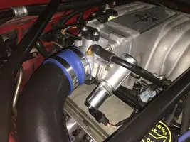
i tried to order a new tps but when I got it it was not the same as the one on the car. It would not plug into the harness and after cutting and splicing I could not get it to read any where close to .98. The car was modified before I got it. Here are a couple pictures.
You are using an out of date browser. It may not display this or other websites correctly.
You should upgrade or use an alternative browser.
You should upgrade or use an alternative browser.
What Throttle Body Is This?
- Thread starter Scott7512
- Start date


The explorer TPS will have a different connector that does not mate with the 5.0 Mustang engine mounted EFI harness, but you already knew that.
What are the wire and stripe colors on the explorer TPS? I have a working explorer throttle body in my shop that I can check against for you.
What are the wire and stripe colors on the explorer TPS? I have a working explorer throttle body in my shop that I can check against for you.
mikestang63
SN Certified Technician
The bbk tps I got from American muscle had black green and red wires and its resistance was a lot higher across it and would not adjust correctly. The connector on the bbk tps looked identical to the one currently on the car but when looking at them side by side the diameter of the inside round section was bigger and would not plug in. Bbk sticker says tp4280072 e472.
Black = signal ground from computer (signal ground is just for the computer sensors)Black green orange.
Green = TPS signal out
Orange = +5 volts Vref from the computer.
If you pull the orange or red plastic center from the TPS connector, you can remove the connector pins. Make a drawing showing the wire color positions on the connector that fits the engine EFI harness; this will be your map to re-pin the new TPS sensor.. Then remove the center from both connectors and swap them so the old connector that fits the engine EFI harness is on the new TPS. Use the map you drew or move the wires one wire at a time.
TPS Troubleshooting and testing
Revised 2 July 2014 to reflect changes in resistance values for testing of TPS wiring.
Setting the TPS: you'll need a good Digital Voltmeter (DVM) to do the job. Set the TPS voltage at .5- 1.1 range. Because of the variables involved with the tolerances of both computer and DVM, I would shoot for somewhere between .6 and 1.0 volts. Unless you have a Fluke or other high grade DVM, the second digit past the decimal point on cheap DVM’s is probably fantasy. Since the computer zeros out the TPS voltage every time it powers up, playing with the settings isn't an effective aid to performance or drivability. The main purpose of checking the TPS is to make sure it isn't way out of range and causing problems.
Wire colors & functions:
Orange/white = 5 volt VREF from the computer
Dark Green/lt green = TPS output to computer
Black/white = Signal ground from computer
TPS troubleshooting steps:
1.) Use the Orange/white & Black white wires to verify the TPS has the correct 5 volts source from the computer.
2.) Use the Dark Green/lt green & Black/white wires to set the TPS base voltage. Try this... All you need is less than 1.0 volt at idle and more than 4.25 at Wide Open Throttle (WOT). You'll need a voltmeter with a 1 or 3 volt low scale to do the job.
The Orange/White wire is the VREF 5 volts from the computer. You use the Dark Green/Lt green wire (TPS signal) and the Black/White wire (TPS ground) to set the TPS. Use a pair of safety pins to probe the TPS connector from the rear of the connector. You may find it a little difficult to make a good connection, but keep trying. Put the safety pins in the Dark Green/Lt green wire and Black/White wire. Make sure the ignition switch is in the Run position but the engine isn't running. Set the voltmeter on the 2 volt range if it doesn’t auto range.
Here’s a TPS tip I got from NoGo50
When you installed the sensor make sure you place it on the peg right and then tighten it down properly. Loosen the back screw a tiny bit so the sensor can pivot and loosen the front screw enough so you can move it just a little in very small increments. I wouldn’t try to adjust it using marks.
(copied from MustangMax, Glendale AZ)
A.) Always adjust the TPS and Idle with the engine at operating temp. Dive it around for a bit if you can and get it nice and warm.
B.) When you probe the leads of the TPS, do not use an engine ground, put the ground probe into the lead of the TPS. You should be connecting both meter probes to the TPS and not one to the TPS and the other to ground.
C.) Always reset the computer whenever you adjust the TPS or clean/change any sensors. I just pull the battery lead for 10 minutes.
D.) The key is to adjust the TPS voltage and reset the computer whenever the idle screw is changed.
The TPS is a variable resistor, must like the volume control knob on a cheap radio. We have all heard them crackle and pop when the volume is adjusted. The TPS sensor has the same problem: wear on the resistor element makes places that create electrical noise. This electrical noise confuses the computer, because it expects to see a smooth increase or decrease as the throttle is opened or closed.
TPS testing: most of the time a failed TPS will set code 23 or 63, but not always. Use either an analog meter or a DVM with an analog bar graph and connect the leads as instructed above. Turn the ignition switch to the Run position, but do not start the engine. Note the voltage with the throttle closed. Slowly open the throttle and watch the voltage increase smoothly, slowly close the throttle and watch the voltage decrease smoothly. If the voltage jumps around and isn’t smooth, the TPS has some worn places in the resistor element. When the throttle is closed, make sure that the voltage is the same as what it was when you started. If it varies more than 10%, the TPS is suspect of being worn in the idle range of its travel.
TPS will not go below 1 volt
Note: Make all resistance checks with the ignition switch in the OFF position. Failure to do so will result in incorrect results and may possibly damage the meter.
Engine mounted sensor circuit: Check the resistance between the black/white wire on the TPS and battery ground. It should be less than 1 ohm. Higher resistance than 1 ohm indicates a problem with the 10 pin connector, computer or the splice inside the main harness where the wire from the 10 pin connectors joins the rest of the black/white wire.
See the graphic for the location of the 10 pin connectors:
Diagram courtesy of Tmoss & Stang&2birds

See the graphic for the 10 pin connector circuit layout.
Unplug the white 10 pin connector to do some resistance testing. It is good time to clean the connector pins and examine the connector for corrosion, broken wire or other damage. See http://oldfuelinjection.com/?p=85 for help in this department.
If the resistance on the TPS Black/White wire and pin 1 of the white engine fuel injector harness 10 pin connector, is more than 1.0 ohm, you have bad connection or broken wiring. Repeat the test using the pin 1 of the white body side 10 pin connector and battery ground. You should have less that 1 ohm. More than that is a damaged signal ground inside the computer or bad connections or wiring.[/b]
Last edited:
The bbk one I got reads around 16k ohms and the one on the car reads around 4K ohms. When the bbk one is on the shaft it has to be turned about half way to get the voltage to .98.
It sounds like the BBK TPS is out of spec for your engine... Time to swap the original TPS back on if it fits the BBK throttle body.The bbk one I got reads around 16k ohms and the one on the car reads around 4K ohms. When the bbk one is on the shaft it has to be turned about half way to get the voltage to .98.
Just picked up another tps from o'rileys and it has the correct connector and correct ohm reading. Americanmuscle.com or bbk must have sent me the wrong one. I noticed that the one pictured on their site is not what I got. Now I can't send it back because I cut the wires.
Similar threads
- Replies
- 30
- Views
- 522
- Replies
- 1
- Views
- 106
Electrical
Stumped No Start...
- Replies
- 8
- Views
- 270
- Replies
- 5
- Views
- 131