Wiring my electric fan, will this work?

88POSLX

Founding Member
Sep 16, 2002
553
0
0
Red Deer, AB
I want to have complete control of the fan myself with the switch, so I can leave it on in the pits without having to leave a key-on. I'll have the LED in the dash as a reminder. Will this work? Is there a better way?


Electricfan.jpg
 
I really dont like that plan, and mine is wired that way. First off, dont get your relay coil power from the battery. Get it from another source, like the cigarette lighter fuse, its always hot. Otherwise your relay coil will pull the same amount of amps as the fan. This will prolly burn up your relay. Also use a slow-blow fuse, or better yet a fusible link. Prolly 14 ga., you can buy them at Napa.

I have mine wired exactly like that and have had the same relay for a couple of years with no probs. I have a Bosch 30amp relay, but most recommend a 75amp relay or so. If you wire your fan like this you will forget to turn it off and kill your battery eventually. Running the fan with the engine off doesnt really do any good. Its cooling the water in the radiator, but its not being circulated unless you have an elec. WP too. Then you may look like a fool when you are ready to stage and the Batt. is dead. I have forgotten to turn mine on a few times, then looked up at the guage and saw 195*. It normally runs at 165*. I havent overheated it, but I can see it coming if I dont put a stat controller in. On the other hand I am even more fanatical about watching the guages with the current setup.
 
Okay, how does this look? The manual switch will be normally on. The fan will continue to run when the car isn't running until the temp switch cuts the circuit. I'll have to watch that the first few times to make sure it isn't an excessively long time. If it is, I'll change to key-on power for 86. With the manual switch, I can still shut the fan off for passes down the track, I'll just have to remember to turn it back on after the pass. This should be a safer method. What do you think?


Electricfan02.jpg
 
I have my electric water pump wired to a thermostatic switch (Moroso #63760) screws into the intake. I have it wired so it has full power all the time. It turns the pump on at 160 degrees and off at 150 degrees (supposed to be 140 degrees) regardless of the key position. I also have an override switch in the car that I can turn it on manually. My fan is wired similar except it has an adjustable control on it. It's nice this way because you don't have to think about it. It's easy to forget to turn these types of things on. Flexalite sells an adjustable fan controller (#31147), or Permacool also sells several different types.
 
Jerry's right - you need to run terminal 30 to ground, and have your led and switch on the hot wire from the fuse box. You don't want your relay/fan ground through the switch or else you'll need a switch that's rated to handle the full amperage of the fan -if you're gonna do that, you might as well just eliminate the relay from the circuit. I forget whether it's 86 or 87 that energizes the relay coil, but that's the circuit to hook your toggle/led up to.
 
Hmmm... maybe I have the wrong relay. It's an SPST, 12V-30amp. The packaging with the relay says 87=12V In, 30=12V out, 85=ground, 86=On/Off switch.

That being said Michael, my wiring should be right?
The one thing I'm confused about is where the power for the relay should come from (86). Jerry said not to use battery power, but instead tap the cigarette power. I don't understand why that's necessary.
 
88POSLX said:
Hmmm... maybe I have the wrong relay. It's an SPST, 12V-30amp. The packaging with the relay says 87=12V In, 30=12V out, 85=ground, 86=On/Off switch.

That being said Michael, my wiring should be right?
The one thing I'm confused about is where the power for the relay should come from (86). Jerry said not to use battery power, but instead tap the cigarette power. I don't understand why that's necessary.

Just a couple replies here:
1. The fle-a-lite controller is a piece of junk. Don't waste your money.
2. I have no clue what your terminal numbers mean. It would help if you using terms like coil, contacts etc.
3. I like the idea of wiring the switch in SERIES with the temp switch. This will prevent you from running your battery dead and will shut off automatically. However, you will need to know the switch position in case you forget and leave it open. In this case, use a DPDT switch and wire one half to the fan circuit and the other half to the led. Make sense. Example: switch up = fan on = led on. Switch down = fan off = led off. There are drawbacks to this, like leaving the switch open and having NO fan and driving home from the track.
But there is a better way....
If you added a seperate temp switch to the toggle switch (now in parallel with the original temp switch circuit leg), you could again PREVENT the batt from draining and tune the "manual" circuit at a lower temperature (for race day). Turn the switch off (open) and your again back to street temperature operation.
In this case, you will always have a fan circuit no matter what position your manual switch is in. This is the safest method.
 
You switch the positive side to remove power from the subsequent circuit. This is a safety practice so you don't short something out accidentally (thinking the circuit is dead when it is not). It's the same reason you don't fuse the ground wire on a circuit.


PS your not an idiot. Everyone knows that the only idiots are chevy owners. (J/K) :rlaugh:
 
GT40XStang9 said:

This circuit will not work.

1. The LED needs a current limiting resistor to prevent it from buring out. Typical Voltage drops across the LED is 1.2 - 1.5 VDC. Typical currents are 10 to 20 milli Amps. The relay will require a large electromotive force to close the large contacts. I would estimate 250 -500mA. YOur LED will not allow the relay to change state in this series circuit.

I wish I could figure out how to post pics here. I could draw this and help everyone visualize the solution. :(
 
BlackFox5.0 said:
Put the LED across the leads on the fan with an appropriate resistor, along with a diode....
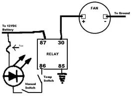
My way seems to require less wiring. I can just grab power from inside the car and then run the ground to the relays ground when it comes into the switch. Doing it across the fan leads would require running wire for both power and ground from the engine bay.

Shoot, just looked at my last diagram... without the switched ground I'm going to have to go across the leads...

Fixed
 
88POSLX said:
Okay, Idwitheld-1... is this what you were talking about? Looks like a pretty safe method to me and still gives me control until the motor gets to 200F.


Electricfan03.jpg


Just move your +12 lead of the LED to the #30 terminal. This will tell you when you have power at the fan. And is great at indicating if the relay contacts have failed or if the coil circuit has failed.

I think this is a very fail safe method AND satisfies your two conditions: Track requirements and street requirements AND an indicator to tell you if you have power at the fan (which is something I have been concerned with on my electric fan setup...as I am affraid the cheap-ass relay from fle-a-lite will fail before I have a chance to replace it). Plus you can not screwup your motor because of a forgoten manual toggle switch! Nice work 88poslx.

Now quit drawing and get to wiring! :D
 
What I was trying to say is, you cant take power from the battery to power the fan (constant hot side of the contacts) and take power from the same place for the relay coil and switch. As Michael Yount stated, you cant have them both running through the same ground either. This is the part of the diagram that really troubles me. You will have to run 10 ga. minimum wires to the switch if you go this way.

The LED's, I am not too familiar with. I can stick my hand out the window and feel the hot air rushing out from under the car with the fan on, thats good enough for me. I can hear it running also. And again, the temp gauge tells the tale if its not doing its job. My $20 taurus fan has served me well. I'm sure I could drive without the fan if I shut it off at long red lights.
 
jerry beach said:
What I was trying to say is, you cant take power from the battery to power the fan (constant hot side of the contacts) and take power from the same place for the relay coil and switch. As Michael Yount stated, you cant have them both running through the same ground either. This is the part of the diagram that really troubles me. You will have to run 10 ga. minimum wires to the switch if you go this way.

Okay, here's how I plan to wire it (using my last diagram). I'll get the fan power (87) from the remote solenoid. The switched power (86) will come from two places. The lone temp switch I'd like to go to the remote solenoid. The manual and temp switch circuit will draw from the cigarette lighter as you stated, since the manual switch will be in the ashtray anyways. I'm not sharing any grounds except for the LED and fan, which I have to. So, will there be a problem with the fan and temp switch both being on the remote solenoid? Will it be a problem using the remote solenoid period? My battery is in the trunk, so this is the easiest way.

Thanks again guys for all the help.
 
I don't see the problem. Just fuse your +12 VDC legs for safety.

Fan wire should be sized accordingly (10 or 12 gauge). All other hots 16 gauge.

IF the hot to the fan is 12 gauge, the ground (out of the fan) should be 12 gauge. If the hot to the coil is 16 gauge the wire out of the coil should be 16 gauge.

You just want to avoid "necking-down" the cross-sectional diameter of the current carrying conductor.