
You are using an out of date browser. It may not display this or other websites correctly.
You should upgrade or use an alternative browser.
You should upgrade or use an alternative browser.
Intake Install
- Thread starter Lovejoy
- Start date


Lower intake coming off? It makes it easier but it could be done with it on.
Just be sure to mark where the rotor is pointing so you can restab it in the same orientation.
Also, buy some long bolts that match the threading of the lower intake bolts. Cut the heads off and thread one in opposite corners. When comes time to drop the lower intake on, use the studs as a guide to lower the intake manifold down onto the blocl
Just be sure to mark where the rotor is pointing so you can restab it in the same orientation.
Also, buy some long bolts that match the threading of the lower intake bolts. Cut the heads off and thread one in opposite corners. When comes time to drop the lower intake on, use the studs as a guide to lower the intake manifold down onto the blocl

Explorer intake swap; you may not have an Explorer intake, but most of the steps are the same. Skip down to All other types of intake manifolds and you find lots of helpful information on what to do to make the job a success.
Explorer specific items
The ACT (Air Charge Temp) sensor will probably need to be moved. The GT 40 lower manifold isn't drilled & tapped for it to go into the intake like the stock manifold was. There is a boss cast into the GT 40, but a machine shop will have to drill & tap the new manifold. The best spot for the ACT is the air box if you don't do the drill and tap thing. You get to cut and splice the 2 ACT wires in order to make them long enough to reach the air box. Solder the wire extensions on the existing wires & use heat shrink tubing to cover the splices. Offset the place where you cut the wires so that you don't have a big bulge when you put heat shrink over the 2 wires to cover & protect them. The air box gets a hole (5/8" or so) for the ACT drilled about 1 1/4" down & 1/1/4" in on the front top side near the upper radiator hose. A brass fitting nut from Home Depot or Ace Hardware secures the ACT into the air box.
If you are very clever, you will find that the ACT connector comes apart so that you can remove the pins. A very small screwdriver releases the lock in the front of the center insert, while another small screwdriver inserted in the back pushes it out. Once the center insert is out of the connector shell, the pins come out easily. New pins are available from AutoZone in a $5 electrical pin kit for Fords. Crimping the pins on the extender wires saves you from having to splice them twice: once to put the connector on and once to extend the wires.
6 ft black 18 gauge wire
6 ft green 18 gauge wire
6 ft 1/4" heat shrink tubing
1 ft 3/16" heat shrink tubing
Measure the 2 extender wires & cut them to length, crimp one set of pins on them. Then mate up the extender pins with the wiring harness & slide the 3/16" heat shrink tubing over them & shrink the tubing. Then slide the 1/4" heat shrink tubing over the pair of wires and shrink the tubing. When you are done you'll have about 1" of wire left without heat shrink tubing on it to strip & crimp the new pins on. Stick the new pins in the old connector shell, assemble it and you are done. It looks as good as factory. Some wire loom can be used to enhance the "Factory Look".
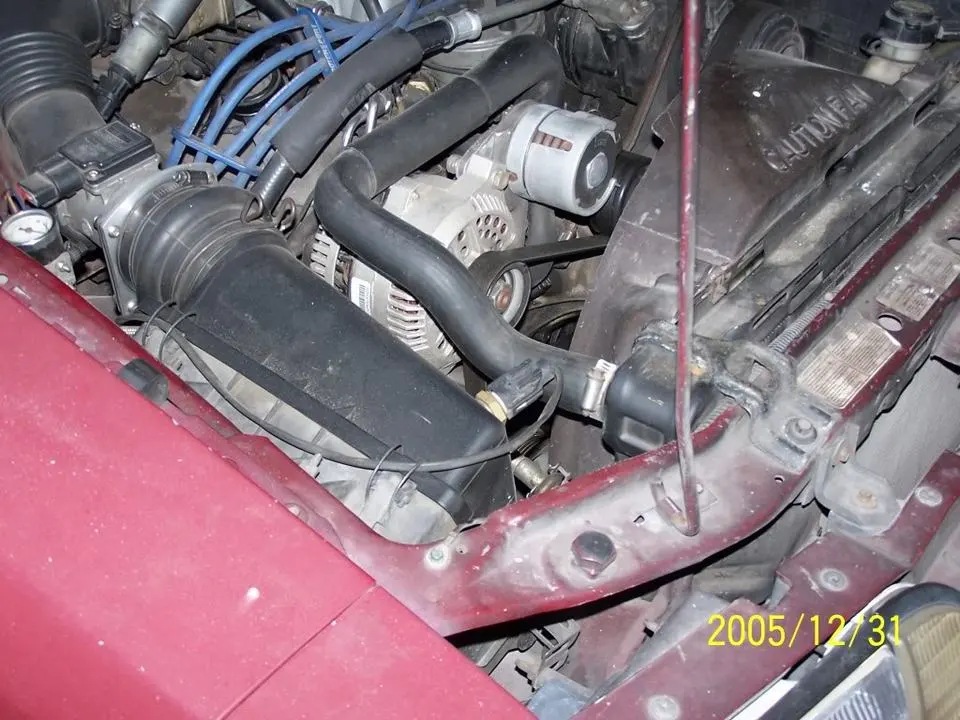
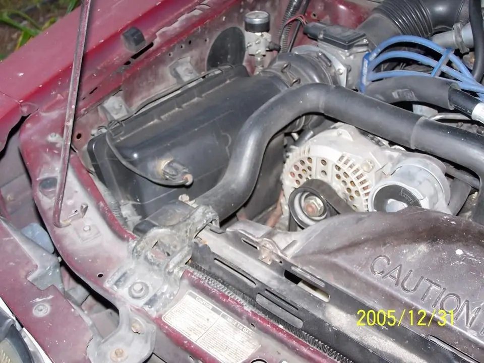
Use the TPS and IAB from your old throttle body. All the EGR passages were there and fit OK. Use you old fuel rails and regulator. You will probably need a new EGR spacer adapter and gaskets. Without the EGR spacer, there is no place to mount the throttle linkage support bracket.
I used the stock water lines on the Explorer manifold and they connected up to the EGR without any problems. I made a “U” out of ½” copper pipe and sweat soldered it together. Then I used it and some hose with clamps to bypass the leaky heater.
The vacuum lines you need are 1 small line for fuel pressure regulator, 1 small line for A/C,1 small line for EGR and another small line for the smog pump. One big line at the back goes to the vacuum tree for the power brake & A/C, one big line goes to the PVC valve. The other big line goes out the front for the carbon canister. In a pinch, one of the small lines can connect to the spare port on the vacuum tree. Cap or plug the remaining lines since they aren't needed.
The stock Explorer linkage didn't come anywhere near fitting, so I made an adapter plate for the throttle linkage so I could use the 65 MM throttle body.
This is what I did:
Make a drawing of the position of the old throttle body linkage arm and its angular position relative to the centerline of the throttle body. Remove the ball stud off the explorer TB to make way for the adapter plate. Drill and tap a 10-32 hole in the linkage parallel to the TB shaft. Make an angle bracket out of 1" angle iron 3/8", drill a 3/16” hole in the center of each one of the legs. Then bolt it on where the hole was drilled & tapped. Then make a circular adapter plate out of 1/4" thick aluminum to bolt the two linkage arms together. Then bolt the aluminum plate to the existing linkage, and the angle bracket. Next mount the arm with the ball stud off the old throttle body on the adapter plate using the drawing to get the angle correct. You will need an aircraft type countersink for one of the bolts that secures the plate to the explorer linkage arm. It ends up being under the arm with the ball stud for the linkage. It works great and looks neat.
The Explorer TB could have been real simple if I had a gas welding torch or taken the TB to a welding shop. Just grind the mushroomed part of the TB shafts so that you can pry the linkage arms off. Then swap the stock arm onto the Explorer TB and braze it onto the shaft. It Takes about 3 minutes or less worth of work with the torch, so it shouldn't cost much.
I didn't have access to a welder, so I fabb'ed the plate in my shop. I took about 1.5 hours to do it, it was a measure, cut, and fit type of operation.
Also see http://www.veryuseful.com/mustang/tech/engine/ConvertingExplorer65mmTB.pdf for modifications to adapt the 65 MM Explorer TB to a Mustang
All other types of intake manifolds
Vacuum line connections:
One large vacuum line from the upper front goes to the carbon canister
One large vacuum line from the rear goes to the vacuum tree.
One small line in the front feeds the Smog pump solenoid control valves on the rear of the passenger side wheel well..
One small line in the rear goes to the fuel pressure regulator.
One small line in the rear goes to the EGR suction regulator.
One large line in the rear goes to the PVC valve.
Diagram courtesy of Tmoss & Stang&2birds - Typical Vacuum Routing for a Fox stang 5.0:
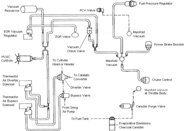
Diagram courtesy of Tmoss & Stang&2birds - Intake manifold bolt tightening sequence for a 5.0 Fox stang:
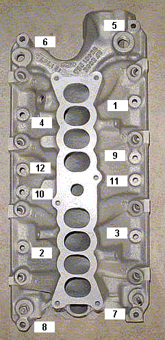
Intake manifold to head bolts
--Step 1 96 in/lbs
--Step 2 16ft/lbs
--Step 3 23-25 ft/lbs
See the following website for some help from Tmoss (diagram designer) & Stang&2Birds (website host) for help on 88-95 wiring Mustang FAQ - Wiring & Engine Info
Here's some tips...
Tools: a good torque wrench is a must have item. A razor blade scraper that holds a single edge razor blade from Home Depot or Ace hardware is another handy thing. Get a Chilton or Haynes shop manual - you'll need it for the bolt torques and patterns. The intake manifold has an especially odd pattern. You'll need access to a timing light to set the timing after you re-stab the distributor. Look in the A/C repair section for the fuel line tools. They look like little plastic top hats. You will need the 1/2" & 5/8" ones. The hat shaped section goes on facing the large part of the coupling. Then you press hard on the brim until it forces the sleeve into the coupling and releases the spring. You may need someone to pull on the line while you press on the coupling. Put some motor oil on them when you put the line back together.
The A/C Compressor comes off with lines still connected. Mark all the electrical, smog and vacuum lines with tags to help you remember where to re-connect them. If you have a digital camera, take several pictures.
Whatever you do, don't skimp on cleaning the gasket surfaces. New gaskets need to seat against bare metal and not the residue left from the old gaskets in order to seal leak free. This is the most time consuming and tiresome part of the job. Put some cardboard in the lifter valley to help catch the gasket scrapings. Have a shop vacuum handy to suck up the scrapings and any coolant that leaked into the lifter valley.
Look for little things that need to be replaced like the short hose from the thermostat hosing to the water pump, damaged vacuum lines and hose clamps that are rusted or broken.
Plan on cutting the thermostat to water pump hose, or removing the thermostat housing. Also plan on removing the distributor to get clearance to remove the intake manifold. Remove #1 spark plug, stick your finger in the spark plug hole and crank. When your finger gets air moving past it, stop cranking. Turn the engine until the timing marks line up with the pointer. Now you can pull the distributor out. Be sure to put a rag or cap in the block where you removed the distributor. It will save you trouble if something falls into the empty distributor hole.
My favorite trick that saves time and effort is the stay in place gasket. Be sure that you scrape (don't use a wire brush) all the old gasket material off, then clean all the surfaces with acetone or MEK.
When the surfaces are clean, use weather strip adhesive on the head to manifold surface. Also use the weather strip adhesive on the side of the gasket that mates to the head. When you are done, the head surface and the gasket surface that mate together will have weather strip adhesive on them. Follow the instructions on the tube or can and when it gets tacky, press the gasket down on the head.
Clean the area where the rubber rails mount to the block in front and in the rear with more acetone or MEK and do the same trick with the weather strip adhesive that you did to the heads.
Coat the rubber seals and the gasket area around the water passages with lots of Blue Silicone gasket sealer and put it together. TADA! no leaks, and no gaskets that shifted out of place.
Fuel injector seal kits with 2 O rings and a pintle cap (Borg-Warner P/N 274081) are available at Pep Boys auto parts. Cost is about $3-$4 per kit. The following are listed at the Borg-Warner site ( http://www.borg-warner.com ) as being resellers of Borg-Warner parts:
Parts Plus – Premium Auto Parts & Accessories or Auto Value or Pep Boys | Tires | Auto Repair & Service | Car Parts | Car Accessories or Federated Auto Parts
Most of the links above have store locators for find a store in your area.
Use motor oil on the O rings when you re-assemble them & everything will slide into place. The gasoline will wash away any excess oil that gets in the wrong places and it will burn up in the combustion chamber. Heat the pintle caps in boiling water to soften them to make them easier to install.
Plan on doing an oil change within 2 hours of run time on the engine. This will get the debris and coolant out of the oil pan.
Consumable items:
Upper manifold gasket
Fel Pro 1250 or equal lower manifold gasket set.
Short formed hose between thermostat hosing and intake manifold
6 ft 7/64" or 1/8" vacuum hose
2 ft 1/2" heater hose
1 1/2 ft 5/8" heater hose
Blue Silicone sealer
ARP antiseize or equal for the bolts
4 each 3/4" hose clamps (spare item in case the old ones are bad)
4 each 1/2" hose clamps (spare item)
What can happen if you don’t use the stay in place gasket…
Ask Nicoleb3x3 about the intake gasket that slipped out of place and caused idle and vacuum leak problems that could not be seen or found by external examination. Spay everything with anything you have, and you won't find the leak...

Explorer specific items
The ACT (Air Charge Temp) sensor will probably need to be moved. The GT 40 lower manifold isn't drilled & tapped for it to go into the intake like the stock manifold was. There is a boss cast into the GT 40, but a machine shop will have to drill & tap the new manifold. The best spot for the ACT is the air box if you don't do the drill and tap thing. You get to cut and splice the 2 ACT wires in order to make them long enough to reach the air box. Solder the wire extensions on the existing wires & use heat shrink tubing to cover the splices. Offset the place where you cut the wires so that you don't have a big bulge when you put heat shrink over the 2 wires to cover & protect them. The air box gets a hole (5/8" or so) for the ACT drilled about 1 1/4" down & 1/1/4" in on the front top side near the upper radiator hose. A brass fitting nut from Home Depot or Ace Hardware secures the ACT into the air box.
If you are very clever, you will find that the ACT connector comes apart so that you can remove the pins. A very small screwdriver releases the lock in the front of the center insert, while another small screwdriver inserted in the back pushes it out. Once the center insert is out of the connector shell, the pins come out easily. New pins are available from AutoZone in a $5 electrical pin kit for Fords. Crimping the pins on the extender wires saves you from having to splice them twice: once to put the connector on and once to extend the wires.
6 ft black 18 gauge wire
6 ft green 18 gauge wire
6 ft 1/4" heat shrink tubing
1 ft 3/16" heat shrink tubing
Measure the 2 extender wires & cut them to length, crimp one set of pins on them. Then mate up the extender pins with the wiring harness & slide the 3/16" heat shrink tubing over them & shrink the tubing. Then slide the 1/4" heat shrink tubing over the pair of wires and shrink the tubing. When you are done you'll have about 1" of wire left without heat shrink tubing on it to strip & crimp the new pins on. Stick the new pins in the old connector shell, assemble it and you are done. It looks as good as factory. Some wire loom can be used to enhance the "Factory Look".
Use the TPS and IAB from your old throttle body. All the EGR passages were there and fit OK. Use you old fuel rails and regulator. You will probably need a new EGR spacer adapter and gaskets. Without the EGR spacer, there is no place to mount the throttle linkage support bracket.
I used the stock water lines on the Explorer manifold and they connected up to the EGR without any problems. I made a “U” out of ½” copper pipe and sweat soldered it together. Then I used it and some hose with clamps to bypass the leaky heater.
The vacuum lines you need are 1 small line for fuel pressure regulator, 1 small line for A/C,1 small line for EGR and another small line for the smog pump. One big line at the back goes to the vacuum tree for the power brake & A/C, one big line goes to the PVC valve. The other big line goes out the front for the carbon canister. In a pinch, one of the small lines can connect to the spare port on the vacuum tree. Cap or plug the remaining lines since they aren't needed.
The stock Explorer linkage didn't come anywhere near fitting, so I made an adapter plate for the throttle linkage so I could use the 65 MM throttle body.
This is what I did:
Make a drawing of the position of the old throttle body linkage arm and its angular position relative to the centerline of the throttle body. Remove the ball stud off the explorer TB to make way for the adapter plate. Drill and tap a 10-32 hole in the linkage parallel to the TB shaft. Make an angle bracket out of 1" angle iron 3/8", drill a 3/16” hole in the center of each one of the legs. Then bolt it on where the hole was drilled & tapped. Then make a circular adapter plate out of 1/4" thick aluminum to bolt the two linkage arms together. Then bolt the aluminum plate to the existing linkage, and the angle bracket. Next mount the arm with the ball stud off the old throttle body on the adapter plate using the drawing to get the angle correct. You will need an aircraft type countersink for one of the bolts that secures the plate to the explorer linkage arm. It ends up being under the arm with the ball stud for the linkage. It works great and looks neat.
The Explorer TB could have been real simple if I had a gas welding torch or taken the TB to a welding shop. Just grind the mushroomed part of the TB shafts so that you can pry the linkage arms off. Then swap the stock arm onto the Explorer TB and braze it onto the shaft. It Takes about 3 minutes or less worth of work with the torch, so it shouldn't cost much.
I didn't have access to a welder, so I fabb'ed the plate in my shop. I took about 1.5 hours to do it, it was a measure, cut, and fit type of operation.
Also see http://www.veryuseful.com/mustang/tech/engine/ConvertingExplorer65mmTB.pdf for modifications to adapt the 65 MM Explorer TB to a Mustang
All other types of intake manifolds
Vacuum line connections:
One large vacuum line from the upper front goes to the carbon canister
One large vacuum line from the rear goes to the vacuum tree.
One small line in the front feeds the Smog pump solenoid control valves on the rear of the passenger side wheel well..
One small line in the rear goes to the fuel pressure regulator.
One small line in the rear goes to the EGR suction regulator.
One large line in the rear goes to the PVC valve.
Diagram courtesy of Tmoss & Stang&2birds - Typical Vacuum Routing for a Fox stang 5.0:
Diagram courtesy of Tmoss & Stang&2birds - Intake manifold bolt tightening sequence for a 5.0 Fox stang:
Intake manifold to head bolts
--Step 1 96 in/lbs
--Step 2 16ft/lbs
--Step 3 23-25 ft/lbs
See the following website for some help from Tmoss (diagram designer) & Stang&2Birds (website host) for help on 88-95 wiring Mustang FAQ - Wiring & Engine Info
Here's some tips...
Tools: a good torque wrench is a must have item. A razor blade scraper that holds a single edge razor blade from Home Depot or Ace hardware is another handy thing. Get a Chilton or Haynes shop manual - you'll need it for the bolt torques and patterns. The intake manifold has an especially odd pattern. You'll need access to a timing light to set the timing after you re-stab the distributor. Look in the A/C repair section for the fuel line tools. They look like little plastic top hats. You will need the 1/2" & 5/8" ones. The hat shaped section goes on facing the large part of the coupling. Then you press hard on the brim until it forces the sleeve into the coupling and releases the spring. You may need someone to pull on the line while you press on the coupling. Put some motor oil on them when you put the line back together.
The A/C Compressor comes off with lines still connected. Mark all the electrical, smog and vacuum lines with tags to help you remember where to re-connect them. If you have a digital camera, take several pictures.
Whatever you do, don't skimp on cleaning the gasket surfaces. New gaskets need to seat against bare metal and not the residue left from the old gaskets in order to seal leak free. This is the most time consuming and tiresome part of the job. Put some cardboard in the lifter valley to help catch the gasket scrapings. Have a shop vacuum handy to suck up the scrapings and any coolant that leaked into the lifter valley.
Look for little things that need to be replaced like the short hose from the thermostat hosing to the water pump, damaged vacuum lines and hose clamps that are rusted or broken.
Plan on cutting the thermostat to water pump hose, or removing the thermostat housing. Also plan on removing the distributor to get clearance to remove the intake manifold. Remove #1 spark plug, stick your finger in the spark plug hole and crank. When your finger gets air moving past it, stop cranking. Turn the engine until the timing marks line up with the pointer. Now you can pull the distributor out. Be sure to put a rag or cap in the block where you removed the distributor. It will save you trouble if something falls into the empty distributor hole.
My favorite trick that saves time and effort is the stay in place gasket. Be sure that you scrape (don't use a wire brush) all the old gasket material off, then clean all the surfaces with acetone or MEK.
When the surfaces are clean, use weather strip adhesive on the head to manifold surface. Also use the weather strip adhesive on the side of the gasket that mates to the head. When you are done, the head surface and the gasket surface that mate together will have weather strip adhesive on them. Follow the instructions on the tube or can and when it gets tacky, press the gasket down on the head.
Clean the area where the rubber rails mount to the block in front and in the rear with more acetone or MEK and do the same trick with the weather strip adhesive that you did to the heads.
Coat the rubber seals and the gasket area around the water passages with lots of Blue Silicone gasket sealer and put it together. TADA! no leaks, and no gaskets that shifted out of place.
Fuel injector seal kits with 2 O rings and a pintle cap (Borg-Warner P/N 274081) are available at Pep Boys auto parts. Cost is about $3-$4 per kit. The following are listed at the Borg-Warner site ( http://www.borg-warner.com ) as being resellers of Borg-Warner parts:
Parts Plus – Premium Auto Parts & Accessories or Auto Value or Pep Boys | Tires | Auto Repair & Service | Car Parts | Car Accessories or Federated Auto Parts
Most of the links above have store locators for find a store in your area.
Use motor oil on the O rings when you re-assemble them & everything will slide into place. The gasoline will wash away any excess oil that gets in the wrong places and it will burn up in the combustion chamber. Heat the pintle caps in boiling water to soften them to make them easier to install.
Plan on doing an oil change within 2 hours of run time on the engine. This will get the debris and coolant out of the oil pan.
Consumable items:
Upper manifold gasket
Fel Pro 1250 or equal lower manifold gasket set.
Short formed hose between thermostat hosing and intake manifold
6 ft 7/64" or 1/8" vacuum hose
2 ft 1/2" heater hose
1 1/2 ft 5/8" heater hose
Blue Silicone sealer
ARP antiseize or equal for the bolts
4 each 3/4" hose clamps (spare item in case the old ones are bad)
4 each 1/2" hose clamps (spare item)
What can happen if you don’t use the stay in place gasket…
Ask Nicoleb3x3 about the intake gasket that slipped out of place and caused idle and vacuum leak problems that could not be seen or found by external examination. Spay everything with anything you have, and you won't find the leak...
Last edited:

mikestang63
SN Certified Technician
makes it a lot easier when you go to lay down the lower intake. If you leave it in place, you have to angle it in from the back and more of a chance of the intake gaskets shifting. I've done it with both the distriubutor in and removed.
mikestang63
SN Certified Technician
makes it a lot easier when you go to lay down the lower intake. If you leave it in place, you have to angle it in from the back and more of a chance of the intake gaskets shifting. I've done it with both the distriubutor in and removed.
yes. the distributor sometimes will get stuck if it has never been removed before. you can put a strap wrench on the housing shaft and turn it back and forth while you are pulling it out. mark the rotor where it points to the distributor hosuing and the distributor housing where it meets the lower intake as reference points before you remove it
Putting the distributor back in and setting the timing.
Note: If you don't have access to a timing light, most of the larger auto parts stores will rent or loan one if you have a credit card or leave a cash deposit.
Revised 28-Jul-2013 to include warning about putting spark plug leads in a different location to attempt a to fix a distributor incorrectly installed.
You can forget about anything beyond this point if you don't have access to a timing light. You will never get the timing set right without one.
Putting the distributor back in is fairly simple. Pull #1 sparkplug, put your finger in the sparkplug hole, crank the engine until you feel compression. Then line up the TDC mark on the balancer with the pointer on the engine block.
The distributor starts out with the #1 plug wire lined up at about 12:00 with you facing it. Align the rotor to about 11:00, since it will turn clockwise as it slides into place.
Align the distributor rotor up with the #1 position marked on the cap, slide the distributor down into the block, (you may have to wiggle the rotor slightly to get the gear to engage) and then note where the rotor is pointing.
If it still lines up with #1 position on the cap, install the clamp and bolt. If not, pull it out and turn 1 tooth forwards or backwards and try again. Put the #1 spark plug back in and tighten it down, put the clamp on the distributor, but don't tighten it too much, as you will have to move the distributor to set the timing. Note that there is no such thing as one tooth off on a 5.0 Mustang if you follow the spark plug wire order on the distributor cap. If it doesn't align perfectly with #1 position, you can turn the distributor until it does. The only problem is that if you are too far one way or the other, you can't turn the distributor enough to get the 10-14 degree optimum timing range. Don't move the wires from the positions shown on the cap on fuel injected engines!!!! The #1 position cast into the cap MUST have the spark plug wire for #1 cylinder in it. Do it differently and the timing for the fuel injectors will be off. The computer uses the PIP sensor to time injector operation by sensing the wide slot in the PIP sensor shutter wheel. If the injector timing of #1 and the firing of #1 do not occur at the right time, the injector timing for all other cylinders will be affected.
Setting the timing:
Paint the mark on the harmonic balancer with paint -choose 10 degrees BTC or 14 degrees BTC or something else if you have NO2 or other power adder. I try to paint TDC red, 10 degrees BTC white and 14 degrees BTC blue.
10 degrees BTC is towards the drivers side marks.
Note: setting the timing beyond the 10 degree mark will give you a little more low speed acceleration. BUT you will need to run 93 octane to avoid pinging and engine damage. Pinging is very hard to hear at full throttle, so it could be present and you would not hear it.
Simplified diagram of what it looks like. Not all the marks are shown for ease of viewing.
ATC ' ' ' ' ' ' ' ' ' '!' ' ' ' ' ' ' ' ' ' BTC
---------------- > Direction of Rotation as viewed standing in front of the engine.
The ' is 2 degrees.
The ! is TDC
The ' is 10 degrees BTC
Set the timing 5 marks BTC. Or if you prefer, 5 marks towards the driver's side to get 10 degrees.
To get 14 degrees, set it 7 marks BTC. Or if you prefer, 7 marks towards the driver's side to get 14 degrees.
The paint marks you make are your friends if you do it correctly. They are much easier to see than the marks machined into the harmonic balancer hub.
At this point hook up all the wires, get out the timing light. Connect timing light up to battery & #1 spark plug. Then start the engine.
Remove the SPOUT connector (do a search if you want a picture of the SPOUT connector) It is the 2 pin rectangular plug on the distributor wiring harness. Only the EFI Mustang engines have a SPOUT. If yours is not EFI, check for a SPOUT: if you don’t find one, skip any instructions regarding the SPOUT
Warning: there are only two places the SPOUT should be when you time the engine. The first place is in your pocket while you are setting the timing and the second is back in the harness when you finish. The little bugger is too easy to lose and too hard to find a replacement.
Start engine, loosen distributor hold down with a 1/2" universal socket. Shine the timing light on the marks and turn the distributor until the mark lines up with the edge of the timing pointer. Tighten down the distributor hold down bolt, Replace the SPOUT connector and you are done.
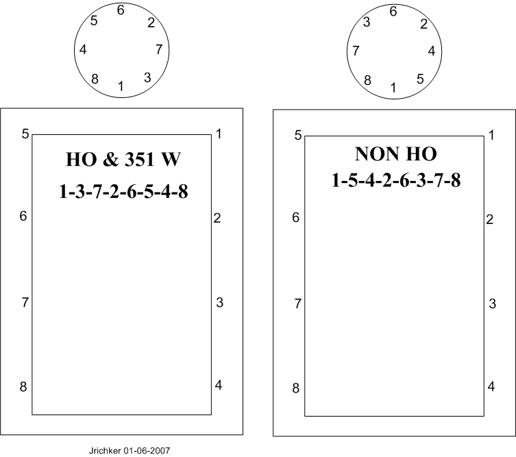
The HO firing order is 1-3-7-2-6-5-4-8.
Non HO firing order is 1-5-4-2-6-3-7-8
Note: If you don't have access to a timing light, most of the larger auto parts stores will rent or loan one if you have a credit card or leave a cash deposit.
Revised 28-Jul-2013 to include warning about putting spark plug leads in a different location to attempt a to fix a distributor incorrectly installed.
You can forget about anything beyond this point if you don't have access to a timing light. You will never get the timing set right without one.
Putting the distributor back in is fairly simple. Pull #1 sparkplug, put your finger in the sparkplug hole, crank the engine until you feel compression. Then line up the TDC mark on the balancer with the pointer on the engine block.
The distributor starts out with the #1 plug wire lined up at about 12:00 with you facing it. Align the rotor to about 11:00, since it will turn clockwise as it slides into place.
Align the distributor rotor up with the #1 position marked on the cap, slide the distributor down into the block, (you may have to wiggle the rotor slightly to get the gear to engage) and then note where the rotor is pointing.
If it still lines up with #1 position on the cap, install the clamp and bolt. If not, pull it out and turn 1 tooth forwards or backwards and try again. Put the #1 spark plug back in and tighten it down, put the clamp on the distributor, but don't tighten it too much, as you will have to move the distributor to set the timing. Note that there is no such thing as one tooth off on a 5.0 Mustang if you follow the spark plug wire order on the distributor cap. If it doesn't align perfectly with #1 position, you can turn the distributor until it does. The only problem is that if you are too far one way or the other, you can't turn the distributor enough to get the 10-14 degree optimum timing range. Don't move the wires from the positions shown on the cap on fuel injected engines!!!! The #1 position cast into the cap MUST have the spark plug wire for #1 cylinder in it. Do it differently and the timing for the fuel injectors will be off. The computer uses the PIP sensor to time injector operation by sensing the wide slot in the PIP sensor shutter wheel. If the injector timing of #1 and the firing of #1 do not occur at the right time, the injector timing for all other cylinders will be affected.
Setting the timing:
Paint the mark on the harmonic balancer with paint -choose 10 degrees BTC or 14 degrees BTC or something else if you have NO2 or other power adder. I try to paint TDC red, 10 degrees BTC white and 14 degrees BTC blue.
10 degrees BTC is towards the drivers side marks.
Note: setting the timing beyond the 10 degree mark will give you a little more low speed acceleration. BUT you will need to run 93 octane to avoid pinging and engine damage. Pinging is very hard to hear at full throttle, so it could be present and you would not hear it.
Simplified diagram of what it looks like. Not all the marks are shown for ease of viewing.
ATC ' ' ' ' ' ' ' ' ' '!' ' ' ' ' ' ' ' ' ' BTC
---------------- > Direction of Rotation as viewed standing in front of the engine.
The ' is 2 degrees.
The ! is TDC
The ' is 10 degrees BTC
Set the timing 5 marks BTC. Or if you prefer, 5 marks towards the driver's side to get 10 degrees.
To get 14 degrees, set it 7 marks BTC. Or if you prefer, 7 marks towards the driver's side to get 14 degrees.
The paint marks you make are your friends if you do it correctly. They are much easier to see than the marks machined into the harmonic balancer hub.
At this point hook up all the wires, get out the timing light. Connect timing light up to battery & #1 spark plug. Then start the engine.
Remove the SPOUT connector (do a search if you want a picture of the SPOUT connector) It is the 2 pin rectangular plug on the distributor wiring harness. Only the EFI Mustang engines have a SPOUT. If yours is not EFI, check for a SPOUT: if you don’t find one, skip any instructions regarding the SPOUT
Warning: there are only two places the SPOUT should be when you time the engine. The first place is in your pocket while you are setting the timing and the second is back in the harness when you finish. The little bugger is too easy to lose and too hard to find a replacement.
Start engine, loosen distributor hold down with a 1/2" universal socket. Shine the timing light on the marks and turn the distributor until the mark lines up with the edge of the timing pointer. Tighten down the distributor hold down bolt, Replace the SPOUT connector and you are done.
The HO firing order is 1-3-7-2-6-5-4-8.
Non HO firing order is 1-5-4-2-6-3-7-8
Last edited:

88LXSleeper
Active Member
- Jan 6, 2016
- 146
- 56
- 48
For $20 I had machine shop drill and tap hole for ACT in extra vacuum line spot on upper manifold.
Similar threads

- Replies
- 16
- Views
- 342
Digital Tuning
Going heads/cam/intake. Do I need a tune?
- Replies
- 41
- Views
- 869
- Replies
- 15
- Views
- 355


- Replies
- 17
- Views
- 413
- Replies
- 7
- Views
- 273
