

You are using an out of date browser. It may not display this or other websites correctly.
You should upgrade or use an alternative browser.
You should upgrade or use an alternative browser.
Progress Thread The next "big" project for my Cobra - T-top conversion coming soon!
- Thread starter LILCBRA
- Start date


extra_stout
5 Year Member

Cool find! You know that you need to make a lot of pics for us in the forum... of both: chicks and cobras
I also bought a new "old" (2010) car
will post pictures, but it's a typical European Ford. Its low mileage and incredibly clean...
Good luck with your find and tune.
I've actually thought of trying my hand at a YouTube documentary of the process. I found one other guy that cut the structure apart, but it's a long and bloated video with a lot of unnecessary stuff in it. Seems that most videos are about 10 minutes so I suppose I'd try to edit them down to that timeframe. I'm sure there is more than one reason that they're that length, but I would say that part of it is keeping someone's attention. But here's that video.
View: https://youtu.be/xRlzUoM7jrg?is=aAak8vANgSrm2VZf
Last edited:
extra_stout
5 Year Member
fathead429
New Member
The Ugachugga scale.
do you re-use the rear mounting bolts for this subframe kit?The Ugachugga scale.
do you re-use the rear mounting bolts for this subframe kit?
Yes you do. I ended up using a breaker bar and socket to twist the spot welded nuts off of the brackets, reinserting the bolts and installing the supplied nuts.
I've really been thinking of this conversion over the last couple days and how the car will end up being weakened some by it. I think what I'm going to do is try to fabricate some web bracing in addition to the added factory T top bracing. I've got a couple rough sketches of my ideas done and think it should work well. I'm planning on making them a bolt in upgrade like the subframe connectors are designed. I figure that way, in the event I need to access anything that they may block, I can remove it all as one unit.
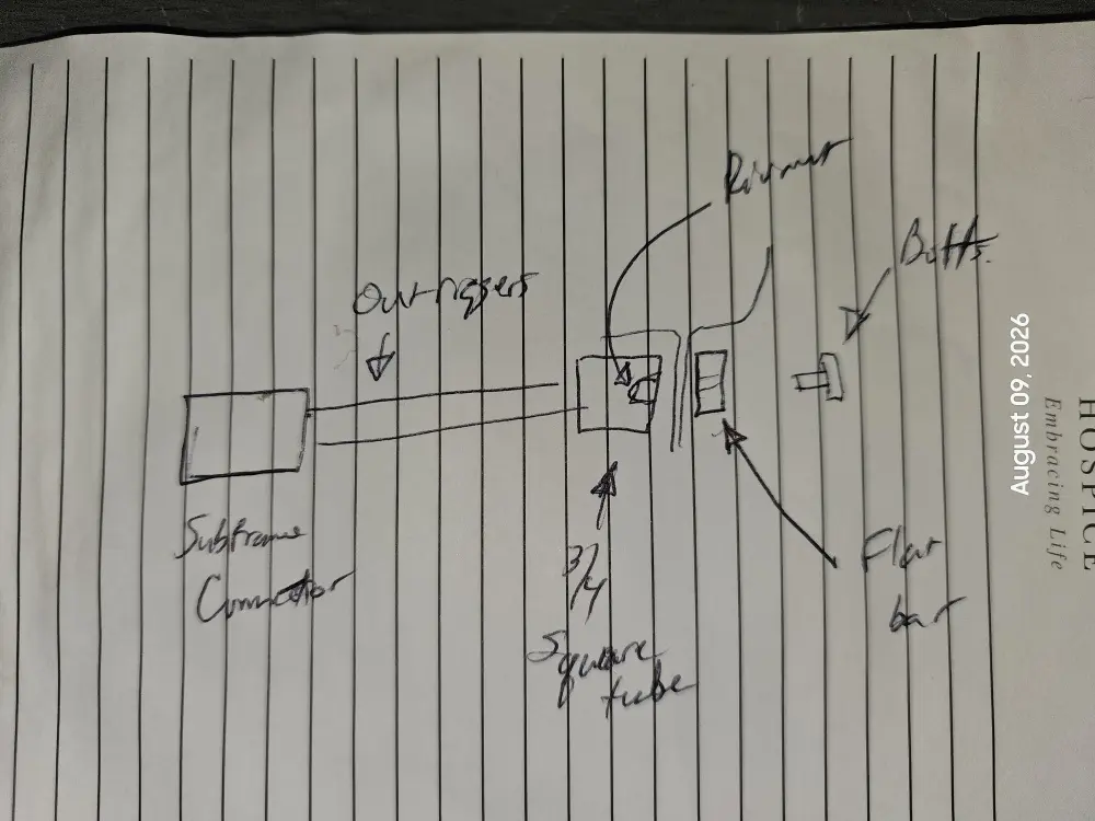
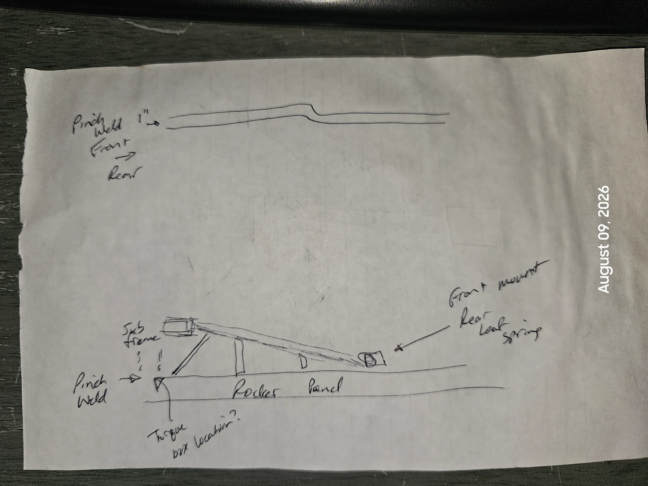
The one difference I've measured out is that the 3/4" square tube I initially thought would be right will be a 1" square tube, 1/8 wall. The clamping piece for the outside of the pinch weld will be 1" x .25.
The one difference I've measured out is that the 3/4" square tube I initially thought would be right will be a 1" square tube, 1/8 wall. The clamping piece for the outside of the pinch weld will be 1" x .25.


Did some measuring and ordered steel. I'll pick it up this weekend but probably won't get started on it right away.
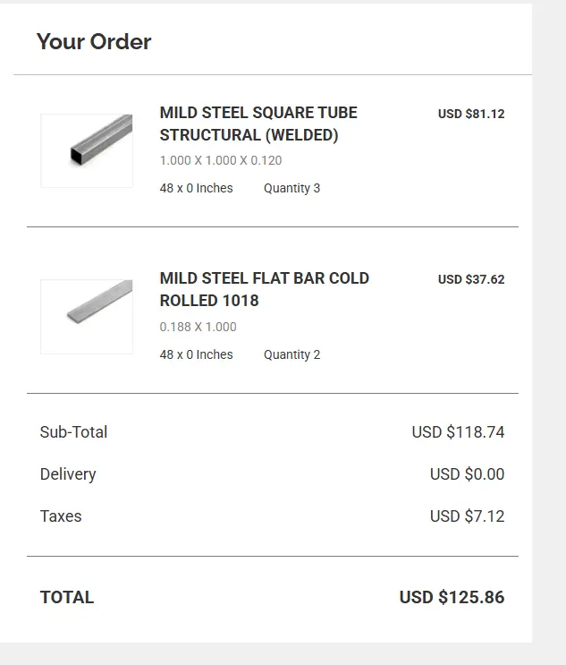
I went with .188 instead of .250 flat stock mainly due to cost. It was an additional $50 if I went with it instead and I don't think that the thinner material will sacrifice anything for how I'm intending on using it.
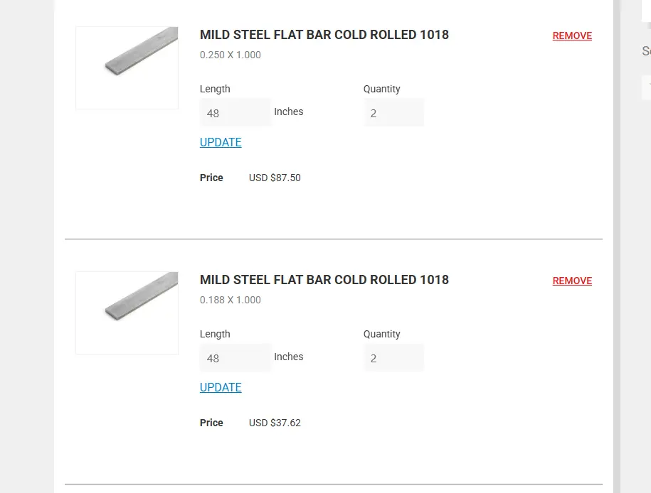
I'll have to take inventory of my rivnut collection to see if I need to order more or not. I'm thinking 5/16 bolts - I feel 3/8 would be overkill and 1/4 wouldn't be quite big enough.
I went with .188 instead of .250 flat stock mainly due to cost. It was an additional $50 if I went with it instead and I don't think that the thinner material will sacrifice anything for how I'm intending on using it.
I'll have to take inventory of my rivnut collection to see if I need to order more or not. I'm thinking 5/16 bolts - I feel 3/8 would be overkill and 1/4 wouldn't be quite big enough.

Blackhawkxx
Advanced Member
- Mar 3, 2023
- 496
- 490
- 73


welder4956
20+ Year Stangneter 
It really depends on where you buy it. Places like Home Depot, Lowes, Tractor Supply, are very expensive. Metal Supermarket and King Metals are a little better. You can get 24 feet of 1" x 1" x 11 gauge tube for $46.46 plus shipping (https://www.kingmetals.com/ECItemMainPage?ItemNumber=6585). Shipping cost may be as much as the metal itself. I go to the local steel supply yards for the best price and they usually have drops so you don't have to buy a whole 20-24 foot stick.Man the price of steel sure has gone up from the years ago when I bought it for subframe type work.
Been thinking of all of this over the weekend, even used @rusty428cj 's pics to help get a visual on layout ideas. I even tried to use AI but it was absolutely useless. 
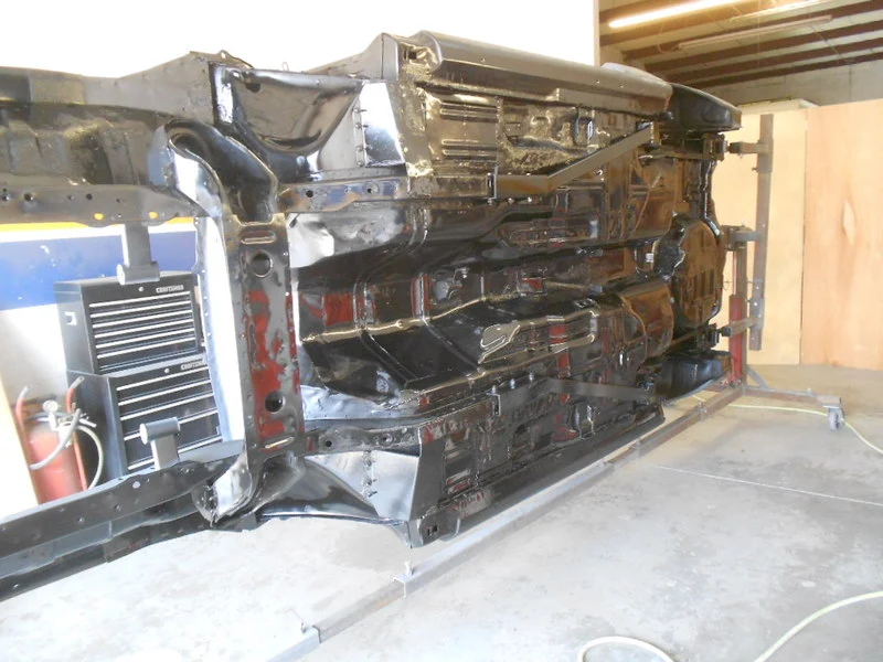
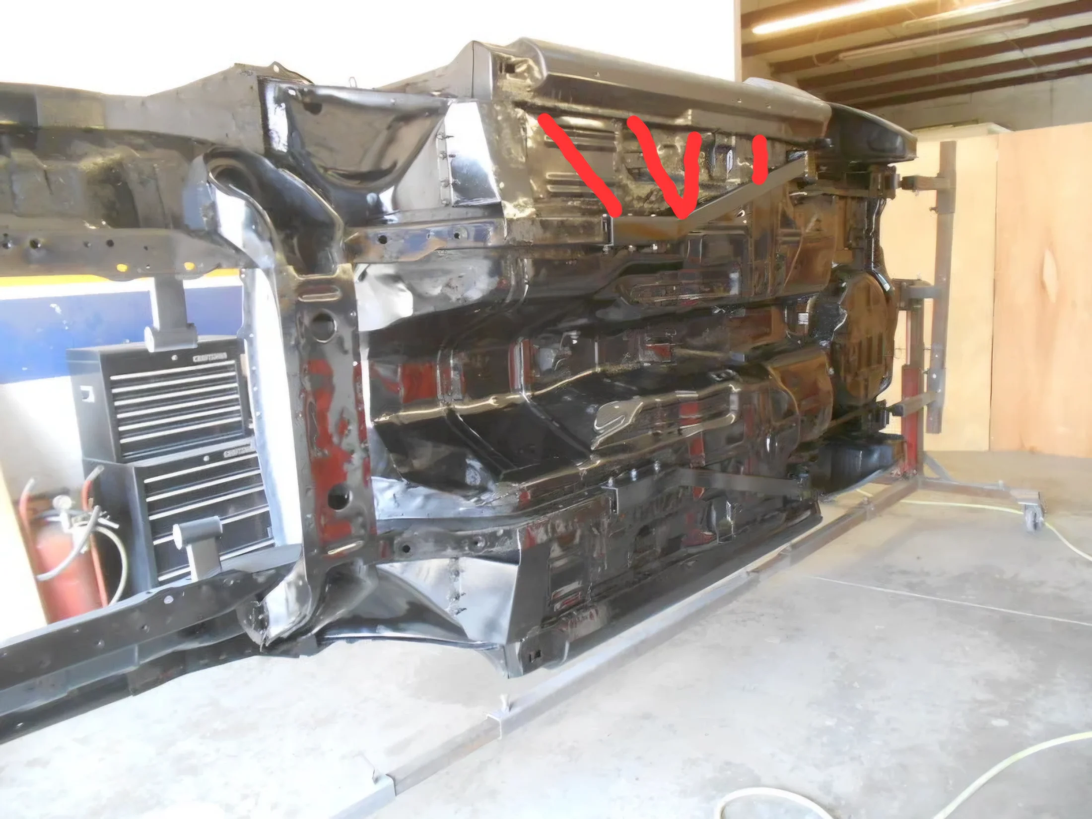
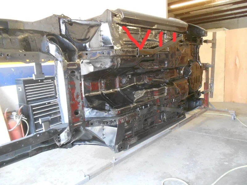
I believe I'll need to get myself another stick or 2 of 1x1x.12 tube. So far that would be 4 of those and 2 - 1x.188 flat stock sticks. I also went ahead and ordered grade 8 bolts, both 1" and 1-3/4", rivnuts and grade 8 nuts. I was thinking I'd go with rivnuts to begin with, but the more I thought about it the more through bolts make sense. I'm looking to clamp the pinch weld and I don't think rivnuts would let me torque the bolts down enough to really work as intended.
I remeasured the overall length tonight to confirm the 48" number and tried to hold one of the tubes up to the pinch weld and found that one of the seat mounts is in the way. It's spot welded to the floor pan and the pinch weld. So, my initial thoughts are that I'll need to trim the bracket enough to fit the tube, then I think I'll get myself a .12 plate to weld to the tube to support the floor and seat.
I also stopped at Harbor Freight and picked up the Hercules cut off saw. It's one of those tools that I've kind of always wanted but could never really justify buying. I figure it'll definitely come in handy when I start working on my Chevy, so I took advantage of their parking lot sale with my $10 Harbor Freight cash and pulled the trigger.
And I still haven't heard back from Bryant about the tune. It's been almost a month since I heard back that he was working his way through his list. He told me he'd jump me up to the top of his queue when I got the car straightened out, I guess he forgot. I'll give it one more week since I'm road tripping to get the T top car next weekend, then I'll bug him again to see if I can get it taken care of before I start tearing the car apart. I'd really like to have it squared away before I do any of the T top stuff.
I believe I'll need to get myself another stick or 2 of 1x1x.12 tube. So far that would be 4 of those and 2 - 1x.188 flat stock sticks. I also went ahead and ordered grade 8 bolts, both 1" and 1-3/4", rivnuts and grade 8 nuts. I was thinking I'd go with rivnuts to begin with, but the more I thought about it the more through bolts make sense. I'm looking to clamp the pinch weld and I don't think rivnuts would let me torque the bolts down enough to really work as intended.
I remeasured the overall length tonight to confirm the 48" number and tried to hold one of the tubes up to the pinch weld and found that one of the seat mounts is in the way. It's spot welded to the floor pan and the pinch weld. So, my initial thoughts are that I'll need to trim the bracket enough to fit the tube, then I think I'll get myself a .12 plate to weld to the tube to support the floor and seat.
I also stopped at Harbor Freight and picked up the Hercules cut off saw. It's one of those tools that I've kind of always wanted but could never really justify buying. I figure it'll definitely come in handy when I start working on my Chevy, so I took advantage of their parking lot sale with my $10 Harbor Freight cash and pulled the trigger.
And I still haven't heard back from Bryant about the tune. It's been almost a month since I heard back that he was working his way through his list. He told me he'd jump me up to the top of his queue when I got the car straightened out, I guess he forgot.
I'll give it one more week since I'm road tripping to get the T top car next weekend, then I'll bug him again to see if I can get it taken care of before I start tearing the car apart. I'd really like to have it squared away before I do any of the T top stuff.
Blackhawkxx
Advanced Member
- Mar 3, 2023
- 496
- 490
- 73
If there are any engineers on here or that you know might be useful in giving the best layout for the supports.Been thinking of all of this over the weekend, even used @rusty428cj 's pics to help get a visual on layout ideas. I even tried to use AI but it was absolutely useless.
Much better drawing than I could do on my phone over the weekend.
I haz mad microslop paint skilzzorz.

My logic behind the diagram:
Small square stock along the inside of your pinch rail. Welded in sections along the length and welded to your existing brace at the tail. - Tied in here, the brace and the new rail have to keep their relationship.
Extend your existing brace along the subframe so that you have something to weld to.
I put in 5 braces but you probably only really need three. Since relationship is fixed at the foot. The braces only need to resist being compressed.
This is what will tie your frame and subframe together at the pinch rail.
I would [still] jack the car at the subframe but that might just be a 'me thing'.
Small square stock along the inside of your pinch rail. Welded in sections along the length and welded to your existing brace at the tail. - Tied in here, the brace and the new rail have to keep their relationship.
Extend your existing brace along the subframe so that you have something to weld to.
I put in 5 braces but you probably only really need three. Since relationship is fixed at the foot. The braces only need to resist being compressed.
This is what will tie your frame and subframe together at the pinch rail.
I would [still] jack the car at the subframe but that might just be a 'me thing'.
My logic behind the diagram:
Small square stock along the inside of your pinch rail. Welded in sections along the length and welded to your existing brace at the tail. - Tied in here, the brace and the new rail have to keep their relationship.
Extend your existing brace along the subframe so that you have something to weld to.
I put in 5 braces but you probably only really need three. Since relationship is fixed at the foot. The braces only need to resist being compressed.
This is what will tie your frame and subframe together at the pinch rail.
I would [still] jack the car at the subframe but that might just be a 'me thing'.
I'm thinking triangulation to resist torsional forces along with lateral bracing. The connector already provides triangulation behind the subframe, so I don't think those would hurt to be 90 degrees to the rocker. Thinking I'd run that front angle as close as I can to the torque box that will be added to my car and already comes added in T top cars. The second one is basically just evening out the spacing, but if it ends up there I think it probably needs tied perpendicular as well. Maybe they both need it? Maybe not? Maybe it could just use a gusset? Maybe they all could use a gusset?

A quick measurement as close as I could figure last night from the front of the channel of the connector to the approximate location of the torque box at roughly 45 degrees comes to about 12 inches. Perpendicular is about 8.
I am using 1 inch square tubing at the rocker, but I'll have to section it to account for an offset about halfway from the front to the rear. And I'm also looking to weld it to the rear most part of the connector, so we're on the same page there.

Since this project is blowing out of proportion (as they all seem to do), I'm thinking floor pan and rocker replacement while I'm at it. May as well, right?!

Similar threads

- Replies
- 2
- Views
- 141
What's it Worth?
1997 Cobra, a ton of mods and restoration
- Replies
- 2
- Views
- 216
- Replies
- 19
- Views
- 804

- Replies
- 3
- Views
- 1K