1989 Gt 306

Do the diagnostics first...
Throwing parts at a problem will just make you poorer and more frustrated.


Cylinder balance test: use this to find dead or weak cylinders:

Revised 19-Dec-2015 to update RPM ranges and include a more complete description of the engine running tests that are done prior to the cylinder balance test. Added YouTube video to show the process.

The computer has a cylinder balance test that helps locate cylinders with low power output. You’ll need to dump the codes out of the computer and make sure that you have the A/C off, clutch depressed to the floor and the transmission in neutral. Fail to do this and you can’t do the engine running dump codes test that allows you to do the cylinder balance test.

Here's the way to dump the computer codes with only a jumper wire or paper clip and the check engine light, or test light or voltmeter. I’ve used it for years, and it works great. You watch the flashing test lamp or Check Engine Light and count the flashes.

Be sure to turn off the A/C, have the clutch depressed to the floor, and put the transmission in neutral when dumping the codes. Fail to do this and you will generate a code 67 and not be able to dump the Engine Running codes.


Here's how to dump the computer codes with only a jumper wire or paper clip and the check engine light, or test light or voltmeter. I’ve used it for years, and it works great. You watch the flashing test lamp or Check Engine Light and count the flashes.

Underhoodpictures007-01.webp


Underhoodpictures010.webp


If your car is an 86-88 stang, you'll have to use the test lamp or voltmeter method. There is no functional check engine light on the 86-88's except possibly the Cali Mass Air cars.

attachment.php?attachmentid=58312&stc=1&d=1242744354.gif


The STI has a gray connector shell and a white/red wire. It comes from the same bundle of wires as the self test connector.

89 through 95 cars have a working Check Engine light. Watch it instead of using a test lamp.

attachment.php?attachmentid=57945&stc=1&d=1240584741.gif


The STI has a gray connector shell and a white/red wire. It comes from the same bundle of wires as the self test connector.


WARNING!!! There is a single dark brown connector with a black/orange wire. It is the 12 volt power to the under the hood light. Do not jumper it to the computer test connector. If you do, you will damage the computer.

What to expect:
You should get a code 11 (two single flashes in succession). This says that the computer's internal workings are OK, and that the wiring to put the computer into diagnostic mode is good. No code 11 and you have some wiring problems. This is crucial: the same wire that provides the ground to dump the codes provides signal ground for the TPS, EGR, ACT and Map/Baro sensors. If it fails, you will have poor performance, economy and drivability problems

Some codes have different answers if the engine is running from the answers that it has when the engine isn't running. It helps a lot to know if you had the engine running when you ran the test.

Dumping the Engine Running codes: The procedure is the same, you start the engine with the test jumper in place. Be sure the A/C is off, clutch depressed to the floor and the transmission is in neutral. You'll get an 11, then a 4 and the engine will speed up to do the EGR test. After the engine speed decreases back to idle, it will dump the engine running codes.

Trouble codes are either 2 digit or 3 digit, there are no cars that use both 2 digit codes and 3 digit codes.

Your 86-88 5.0 won't have a working Check Engine Light, so you'll need a test light.
See AutoZone Part Number: 25886 , $10
4.webp


Alternate methods:
For those who are intimidated by all the wires & connections, see Actron® for what a typical hand scanner looks like. Normal retail price is about $30 or so at AutoZone or Wal-Mart.

Or for a nicer scanner see www.midwayautosupply.com/Equus-Digital-Ford-Code-Reader/dp/B000EW0KHW Equus - Digital Ford Code Reader (3145It has a 3 digit LCD display so that you don’t have to count flashes or beeps.. Cost is $22-$36.


Cylinder balance test

If you have idle or IAC/IAB problems and the engine will not idle on its own without mechanically adjusting the base idle speed above 625-750 RPM, this test will fail with random cylinders pointed out every time it runs. The IAC/IAB must be capable of controlling the engine speed to run in the 1300-1500 RPM range. Playing with the base idle speed by adjusting it upwards will not work, the computer has to be able to control the engine speed using the IAC/IAB.

Warm the car's engine up to normal operating temperature. With the test jumper in test position, start the engine and let it stabilize. It should flash a 10 and then a 4 and maybe an 11. If no 11, then there are other codes that will be dumped.
One of the first tests it does is to open the EGR all the way, this will cause the engine to stumble and almost die. If the engine dies here then you have EGR problems.
To start the cylinder balance test, briefly floor the accelerator past 2500 RPM and let off the accelerator. The engine will stabilize at about 1300-1450 RPM and the cut off the fuel injectors one at a time. The engine speed will drop briefly and the computer will turn the fuel injector for the cylinder under test back on. Then it starts the process for the next cylinder. When it has sequenced through all 8 injectors, it will flash 9 for everything OK, or the number of the failing cylinder such as 2 for cylinder #2. Quickly pressing the throttle again up to 2500 RPM’s will cause the test to re-run with smaller qualifying figures.
Do it a third time, and if the same cylinder shows up, the cylinder is weak and isn’t putting out power like it should. See the Chilton’s Shop manual for the complete test procedure

See
View: https://www.youtube.com/watch?v=HDXrkKS4jTE
for a visual tour through the process. There is no voice narration so you have to listen carefully for the engine sounds.

Do a compression test on all the cylinders.
Take special note of any cylinder that shows up as weak in the cylinder balance test. Low compression on one of these cylinders rules out the injectors as being the most likely cause of the problem. Look at cylinders that fail the cylinder balance test but have good compression. These cylinders either have a bad injector, bad spark plug or spark plug wire. Move the wire and then the spark plug to another cylinder and run the cylinder balance test again. If it follows the moved wire or spark plug, you have found the problem. If the same cylinder fails the test again, the injector is bad. If different cylinders fail the cylinder balance test, you have ignition problems or wiring problems in the 10 pin black & white electrical connectors located by the EGR.

How to do a compression test:
Only use a compression tester with a screw in adapter for the spark plug hole. The other type leaks too much to get an accurate reading. Your local auto parts store may have a compression tester to rent/loan. If you do mechanic work on your own car on a regular basis, it would be a good tool to add to your collection.

With the engine warmed up, remove all spark plugs and prop the throttle wide open with a plastic screwdriver handle between the throttle butterfly and the throttle housing. Crank the engine until it the gage reading stops increasing. On a cold engine, it will be hard to tell what's good & what's not. Some of the recent posts have numbers ranging from 140-170 PSI. If the compression is low, squirt some oil in the cylinder and do it again – if it comes up, the rings are worn. There should be no more than 10% difference between cylinders. Use a blow down leak test (puts compressed air inside cylinders) on cylinders that have more than 10% difference.

I generally use a big screwdriver handle stuck in the TB between the butterfly and the TB to prop the throttle open. The plastic is soft enough that it won't damage anything and won't get sucked down the intake either.

A battery charger (not the trickle type) is a good thing to have if you haven't driven the car lately or if you have any doubts about the battery's health. Connect it up while you are cranking the engine and it will help keep the starter cranking at a consistent speed from the first cylinder tested to the last cylinder.
 
Here goes the bad news...

I suggest that you print this post out and have it handy when you do the testing & troubleshooting work.

Fix the code 22 first; see the code 22 the test path below.


Then pull the spark plug from #8 cylinder; it is the driver side rear spark plug.
The cylinder balance test pointed to it as being non functional. Check the spark plug for fouling or damage, then use an ohmmeter to check the resistance of the spark plug wire. It should be between 2000-8000 ohms, less is OK, much more than those numbers in not good. Check the spark plug wire and distributor cap for jumping spark, cracks or burned spots. If the spark plug, distributor cap and spark plug wire are all good,then do a compression test. Most auto parts stores will rent or loan a compression tester if you have a credit card or make a cash deposit. If the spark plug, spark plug wire, distributor cap and compression test are all good, then the fuel injector and wiring are suspect. I will help that that problem if it is needed after you have eliminated everything else that I have named.

The rest of your codes are emission related. Someone removed, disconnected or disabled the emissions equipment in an effort to make the car faster. That DOES NOT WORK!!!! All it does is to make the computer to spit codes and cause other problems. All the emissions equipment shuts off when you go WOT (Wide Open Throttle) and does not negatively affect performance to any great extent.


MAP/BARO sensor operation and code 22

Revised 14-Nov-2014 to add wire colors for frequency & voltage testing and engine sensor wiring diagrams.

On a Speed Density car, the MAP/BARO sensor is connected to the intake manifold and acts to sense the manifold pressure. Lower vacuum inside the intake manifold when combined with more throttle opening measured by the TPS means more airflow through the engine. As airflow increases, fuel flow through the injectors needs to increase to keep the air/fuel ratio where it needs to be. When manifold vacuum increases, the engine is either decelerating or idling, and it needs to reduce the fuel flow through the injectors.

On a Mass Air car, the MAP/BARO sensor vents to open air and actually senses the barometric pressure due to changes in weather and altitude. Its purpose is to set a baseline for the computer to know the barometric pressure. As barometric pressure decreases, it leans out the fuel flow to compensate for less oxygen in the air. When the barometric pressure rises, it increases to add fuel since there is more oxygen in the air. The fuel requirements decrease as altitude increases, since the atmospheric pressure decreases.

Disconnecting the MAP or BARO sensor will set code 22.

Misconnecting the BARO sensor to vacuum on a Mass Air car will cause the computer to lean out the fuel mixture.

Code 22 or 126 MAP (vacuum) or BARO signal out of range. The MAP or BARO sensor is pretty much the same sensor for both Mass Air & Speed Density cars. The main difference is where it is connected. Mass Air cars vent it to the atmosphere, while Speed Density cars connect it to the intake manifold vacuum. Its purpose is to help set a baseline for the air/fuel mixture by sensing changes in barometric pressure. The MAP or BAP sensor puts out a 5 volt square wave that changes frequency with variations in atmospheric pressure. The base is 154 HZ at 29.92" of mercury - dry sunny day at sea level, about 68-72 degrees. You need an oscilloscope or frequency meter to measure it. There a very few DVM’s with a price tag under $40 that will measure frequency, but there are some out there.

Map sensor wiring:
black/white - ground
orange/white or +5 volts power
white/red signal out.

Measure the +5 volt supply using the orange/white and black/white wires
Measure the signal using the black/white and white/red wires.

The MAP/BARO sensor is mounted on the firewall behind the upper manifold on 86-93 Mustangs.

Baro or MAP test using a real frequency meter - run the test key on, engine off. The noise from the ignition system will likely upset the frequency meter. I used a 10 x oscilloscope probe connected from the frequency meter to the MAP/BAP to reduce the jitter in the meter's readout. And oscilloscope is very useful if you have access to one or know of someone who does. With an oscilloscope, you can see the waveform and amplitude.

If it is defective, your air/fuel ratio will be off and the car’s performance & emissions will suffer

Some basic checks you can make to be sure that the sensor is getting power & ground:
Note that all resistance tests must be done with power off. Measuring resistance with a circuit powered on will give false readings and possibly damage the meter.
Check the resistance between the black/white wire on the MAP/BARO sensor and then the black/white wire on the EGR and the same wire on the TPS. It should be less than 1 ohm. Next check the resistance between the black/white wire and the negative battery cable. It should be less than 1.5 ohm.

The following power on check requires you to turn the ignition switch to the Run position.
Use a DVM to check for 5 volts on the orange/white wire. If it is missing, look for +5 volts at the orange/white wire on the TPS or EGR sensors. Use the black/white wire for the ground for the DVM.
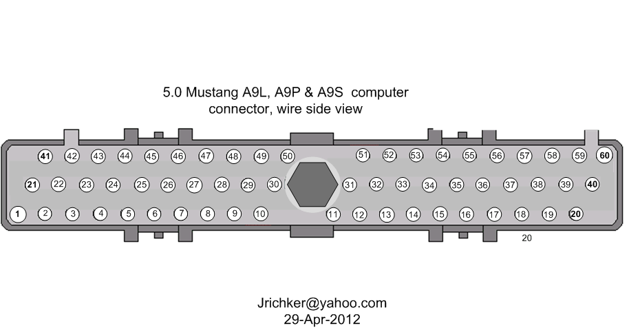
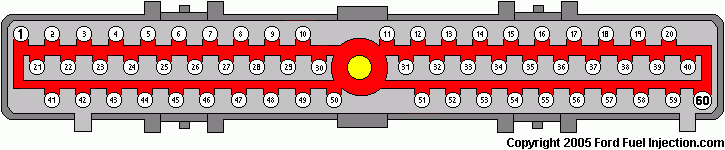
a9x-series-computer-connector-wire-side-view-gif.71316.gif


eec-iv-computer-connector-for-5-0-mustang-gif.88243.gif


Diagrams courtesy of Tmoss & Stang&2birds

Complete computer, actuator & sensor wiring diagram for 88-91 Mass Air Mustangs
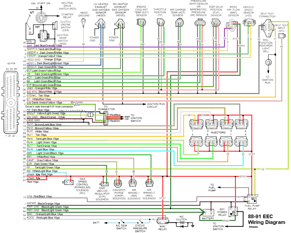
88-91_5.0_EEC_Wiring_Diagram.gif


Complete computer, actuator & sensor wiring diagram for 91-93 Mass Air Mustangs
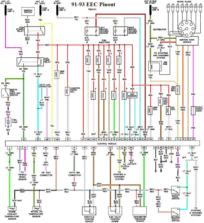
91-93_5.0_EEC_Wiring_Diagram.gif


See the following website for some help from Tmoss (diagram designer) & Stang&2Birds (website host) for help on 88-95 wiring http://www.veryuseful.com/mustang/tech/engine/ Everyone should bookmark this site.

Complete computer, actuator & sensor wiring diagram for 91-93 Mass Air Mustangs
http://www.veryuseful.com/mustang/tech/engine/images/91-93_5.0_EEC_Wiring_Diagram.gif

Complete computer, actuator & sensor wiring diagram for 88-91 Mass Air Mustangs
http://www.veryuseful.com/mustang/tech/engine/images/88-91_5.0_EEC_Wiring_Diagram.gif

Ignition switch wiring
http://www.veryuseful.com/mustang/tech/engine/images/IgnitionSwitchWiring.gif

Fuel, alternator, A/C and ignition wiring
http://www.veryuseful.com/mustang/tech/engine/images/fuel-alt-links-ign-ac.gif

O2 sensor wiring harness
http://www.veryuseful.com/mustang/tech/engine/images/mustangO2Harness.gif

Vacuum diagram 89-93 Mustangs
http://www.veryuseful.com/mustang/tech/engine/images/mustangFoxFordVacuumDiagram.jpg

HVAC vacuum diagram
http://www.veryuseful.com/mustang/tech/engine/images/Mustang_AC_heat_vacuum_controls.gif

TFI module differences & pin out
http://www.veryuseful.com/mustang/tech/engine/images/TFI_5.0_comparison.gif

Fuse box layout
http://www.veryuseful.com/mustang/tech/engine/images/MustangFuseBox.gif

87-92 power window wiring
http://www.veryuseful.com/mustang/tech/engine/images/mustang87-92 PowerWindowWiring.gif

93 power window wiring
http://www.veryuseful.com/mustang/tech/engine/images/mustang93PowerWindows.gif

T5 Cutaway showing T5 internal parts
http://www.veryuseful.com/mustang/tech/engine/images/5_Speed_Cutaway_Illustrated.jpg

Visual comparison of the Ford Fuel Injectors, picture by TMoss:
http://www.veryuseful.com/mustang/tech/engine/images/Ford_Injector_Guide.jpg


Code 12 -Idle Air Bypass motor not controlling idle properly (generally idle too low) - IAB dirty or not working. Clean the electrical contacts with non flammable brake parts cleaner at the same time.

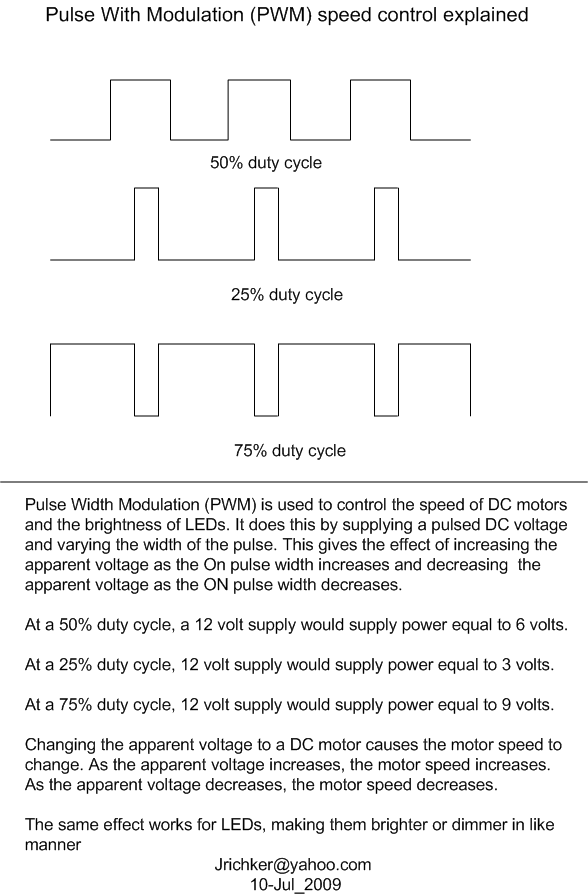
IAC doesn't work: look for +12 volts at the IAC red wire. Then check for continuity between the white/lt blue wire and pin 21 on the computer. The IAC connector contacts will sometimes corrode and make the IAC not work. The red wire on the IAC is always hot with the engine in run mode. The computer provides a ground for the current for the IAC. It switches the ground on and off, making a square wave with a varying duty cycle. A normal square wave would be on for 50% of the time and off for 50% of the time. When the idle speed is low, the duty cycle increases more than 50% to open the IAC more. When the engine speed is high, it decreases the duty cycle to less than 50% to close the IAC. An old-fashioned dwell meter can be used to check the change: I haven’t tried it personally, but it should work. In theory, it should read ½ scale of whatever range you set it on with a 50% duty cycle. An Oscilloscope is even better if you can find someone who has one and will help.
attachment.php?attachmentid=58887&stc=1&d=1247241098.gif


Recommended procedure for cleaning the IAC/IAB:
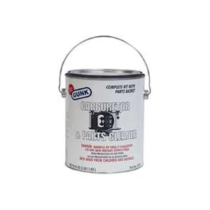
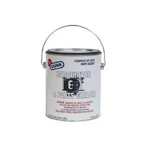
Conventional cleaning methods like throttle body cleaner aren’t very effective. The best method is a soak type cleaner used for carburetors. If you are into fixing motorcycles, jet skis, snowmobiles or anything else with a small carburetor, you probably have used the one gallon soak cleaners like Gunk or Berryman. One of the two should be available at your local auto parts store for $22-$29. Take the solenoid off the body and set it aside: the carb cleaner will damage some types of plastic parts. Soak the metal body in the carb cleaner overnight. There is a basket to set the parts in while they are soaking. When you finish soaking overnight, twist the stem of the IAB/IAC that sticks out while the blocker valve is seated. This removes any leftover deposits from the blocker valve seat. Rinse the part off with water and blow it dry with compressed air. The IAC/IAB should seal up nicely now. Once it has dried, try blowing through the bottom hole and it should block the air flow. Reassemble and reinstall to check it out.

Gunk Dip type carb & parts soaker:
21hb0QWbOeL._SL500_AA300_.jpg


Setting the base idle speed:
First of all, the idle needs to be adjusted to where the speed is at or below 600 RPM with the IAC disconnected. If you have a wild cam, you may have to raise this figure 100-150 RPM or so. Then the electrical signal through the IAC can vary the airflow through it under computer control. Remember that the IAC can only add air to increase the base idle speed set by the mechanical adjustment. The 600 RPM base idle speed is what you have after the mechanical adjustment. The IAC increases that speed by supplying more air under computer control to raise the RPM’s to 650-725 RPM’s. This figure will increase if you have a wild cam, and may end up between 800-950 RPM

Remember that changing the mechanical idle speed adjustment changes the TPS setting too.

This isn't the method Ford uses, but it does work. Do not attempt to set the idle speed until you have fixed all the codes and are sure that there are no vacuum leaks.

Disconnect the battery negative terminal and turn the headlights on. Leave the battery negative terminal disconnected for 5 minutes or so. Then turn the headlights off and reconnect the battery. This erases the computer settings that may affect idle performance.

Warm the engine up to operating temperature, place the transmission in neutral, and set the parking brake. Turn off lights, A/C, all unnecessary electrical loads. Disconnect the IAC electrical connector. Remove the SPOUT plug. This will lock the ignition timing so that the computer won't change the spark advance, which changes the idle speed. Note the engine RPM: use the mechanical adjustment screw under the throttle body to raise or lower the RPM until you get the 600 RPM mark +/- 25 RPM. A wild cam may make it necessary to increase the 600 RPM figure to 700 RPM or possibly a little more to get a stable idle speed.
Changing the mechanical adjustment changes the TPS, so you will need to set it.

When you are satisfied with the results, turn off the engine, and re-install the SPOUT and reconnect the IAC. The engine should idle with the range of 650-750 RPM without the A/C on or extra electrical loads. A wild cam may make this figure somewhat higher.

An engine that whose idle speed cannot be set at 600 RPM with the IAC disconnected has mechanical problems. Vacuum leaks are the #1 suspect in this case. A vacuum gauge will help pinpoint both vacuum leaks and improperly adjusted valves. A sticking valve or one adjusted too tight will cause low vacuum and a 5"-8" sweep every time the bad cylinder comes up on compression stroke. An extreme cam can make the 600 RPM set point difficult to set. Contact your cam supplier or manufacturer to get information on idle speed and quality


Code 33 - Insufficient EGR flow detected.
Look for vacuum leaks, cracked vacuum lines, failed EGR vacuum regulator. Check to see if you have 10” of vacuum at the EGR vacuum connection coming from the intake manifold. Look for electrical signal at the vacuum regulator solenoid valves located on the rear of the passenger side wheel well. Using a test light across the electrical connector, it should flicker as the electrical signal changes. Remember that the computer does not source any power, but provides the ground necessary to complete the circuit. That means one side of the circuit will always be hot, and the other side will go to ground or below 1 volt as the computer switches on that circuit.
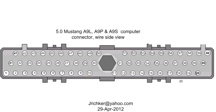
Check for resistance between the brown/lt green wire on the EGR sensor and pin 27 on the computer: you should have less than 1.5 ohm.

Backside view of the computer wiring connector:
a9x-series-computer-connector-wire-side-view-gif.71316


See the following website for some help from Tmoss (diagram designer) & Stang&2Birds (website host)

http://www.veryuseful.com/mustang/tech/engine/images/fuel-alt-links-ign-ac.gif

http://www.veryuseful.com/mustang/tech/engine/images/88-91eecPinout.gif


EGR test procedure courtesy of cjones

to check the EGR valve:
bring the engine to normal temp.

connect a vacuum pump to the EGR Valve or see the EGR test jig drawing below. Connnect the test jig or to directly to manifold vacuum.

Do not connect the EGR test jig to the EVR (Electronic Vacuum Regulator).


apply 5in vacuum to the valve. Using the test jig, use your finger to vary the vacuum

if engine stumbled or died then EGR Valve and passage(there is a passageway through the heads and intake) are good.

if engine did NOT stumble or die then either the EGR Valve is bad and/or the passage is blocked.

if engine stumbled, connect EGR test jig to the hose coming off of the EGR Valve.
Use your finger to cap the open port on the vacuum tee.
snap throttle to 2500 RPM (remember snap the throttle don't hold it there).
did the vacuum gauge show about 2-5 in vacuum?
if not the EVR has failed

EGR test jig
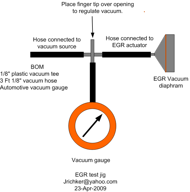
egr-test-jig-gif.58022


The operation of the EGR vacuum regulator can be checked by using a test light applied across the wiring connector. Jumper the computer into self test mode and turn the key on but do not start the engine. You will hear all the actuators (including the EVR vacuum regulator) cycle. Watch for the light to flicker: that means the computer has signaled the EGR vacuum regulator successfully.


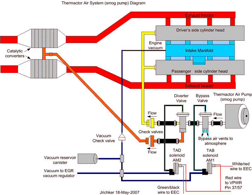
Codes 44 & 94 - AIR system inoperative - Air Injection. Check vacuum lines for leaks, & cracks. Check for a clogged air crossover tube, where one or both sides of the tube clog with carbon.
attachment.php


Revised 21 Sep 2012 to correct the description of the process that sets the code and include Thermactor Air System diagram.

If you have a catalytic converter H pipe, you need to fix these codes. If you don't, then don't worry about them.

Code 44 RH side air not functioning.
Code 94 LH side air not functioning.

The TAD solenoid/TAD diverter valve directs smog pump output to either the crossover tube attached to the cylinder heads or to the catalytic converters.

The O2 sensors are placed before the catalytic converters, so they do not see the extra O2 when the smog pump's output is directed to the converters or the input just before the converter.

The 44/94 code uses the O2 sensors to detect a shift in the O2 level in the exhaust. The smog pump provides extra air to the exhaust which raises the O2 level in the exhaust when the smog pump output is directed through the crossover tube.

When there is an absence of increase in the O2 levels when the TAD solenoid/TAD diverter valve directs air through the crossover tube, it detects the lower O2 level and sets the code.

Failure mode is usually due to a clogged air crossover tube, where one or both sides of the tube clog with carbon. The air crossover tube mounts on the back of the cylinder heads and supplies air to each of the Thermactor air passages cast into the cylinder heads. When the heads do not get the proper air delivery, they set codes 44 & 94, depending on which passage is clogged. It is possible to get both 44 & 94, which would suggest that the air pump or control valves are not working correctly, or the crossover tube is full of carbon or missing.

Testing the system:
Note that the engine must be running to do the tests unless stated otherwise. For safety’s sake, do test preparation like loosening clamps, disconnecting hoses and connecting things to a vacuum source with the engine off.


Disconnect the big hose from smog pump: with the engine running you should feel air output. Reconnect the smog pump hose & apply vacuum to the first vacuum controlled valve: Its purpose is to either dump the pump's output to the atmosphere or pass it to the next valve.

The next vacuum controlled valve directs the air to either the cylinder heads when the engine is cold or to the catalytic converter when the engine is warm. Disconnect the big hoses from the back side of the vacuum controlled valve and start the engine. Apply vacuum to the valve and see if the airflow changes from one hose to the next.

The two electrical controlled vacuum valves mounted on the rear of the passenger side wheel well turn the vacuum on & off under computer control. Check to see that both valves have +12 volts on the red wire. Then ground the white/red wire and the first solenoid should open and pass vacuum. Do the same thing to the light green/black wire on the second solenoid and it should open and pass vacuum.

Remember that the computer does not source power for any actuator or relay, but provides the ground necessary to complete the circuit. That means one side of the circuit will always be hot, and the other side will go to ground or below 1 volt as the computer switches on that circuit.

The following computer tests are done with the engine not running.
The computer provides the ground to complete the circuit to power the solenoid valve that turns the
vacuum on or off. The computer is located under the passenger side kick panel. Remove the kick panel & the cover over the computer wiring connector pins. Check Pin 38 Solenoid valve #1 that provides vacuum to the first Thermactor control valve for a switch from 12-14 volts to 1 volt or less. Do the same with pin 32 solenoid valve #2 that provides vacuum to the second Thermactor control valve. Turning the ignition to Run with the computer jumpered to self-test mode will cause all the actuators to toggle on and off. If after doing this and you see no switching of the voltage on and off, you can start testing the wiring for shorts to ground and broken wiring. An Ohm check to ground with the computer connector disconnected & the solenoid valves disconnected should show open circuit between the pin 32 and ground and again on pin 38 and ground. In like manner, there should be less than 1 ohm between pin 32 and solenoid valve #2 and pin 38 & Solenoid valve #1.

The following computer tests are done with the engine running.
If after checking the resistance of the wiring & you are sure that there are no wiring faults, start looking at the solenoid valves. If you disconnect them, you can jumper power & ground to them to verify operation with the engine running. Power & ground supplied should turn on the vacuum flow, remove either one and the vacuum should stop flowing.

Typical resistance of the solenoid valves is in the range of 20-70 Ohms.

See the following website for some help from Tmoss (diagram designer) & Stang&2Birds (website host)

http://www.veryuseful.com/mustang/tech/engine/images/fuel-alt-links-ign-ac.gif

http://www.veryuseful.com/mustang/tech/engine/images/88-91eecPinout.gif

If you have a catalytic converter H pipe, you need to fix these codes. If you don't, then don't worry about them

Code 85 CANP solenoid - The Carbon Canister solenoid is inoperative or missing.

Revised 11 –Jan_2015 to add warning about vacuum leaks due to deteriorated hose or missing caps on vacuum lines when the solenoid is removed.

Check vacuum lines for leaks and cracks. Check electrical wiring for loose connections, damaged wiring and insulation. Check solenoid valve operation by grounding the gray/yellow wire to the solenoid and blowing through it.
The computer provides the ground for the solenoid. The red wire to the solenoid is always energized any time the ignition switch is in the run position.

If you disconnected the carbon canister and failed to properly cap the vacuum line coming from under the upper intake manifold, you will have problems. You will also have problems if the remaining hose coming from under the upper intake manifold or caps for the vacuum line are sucking air.

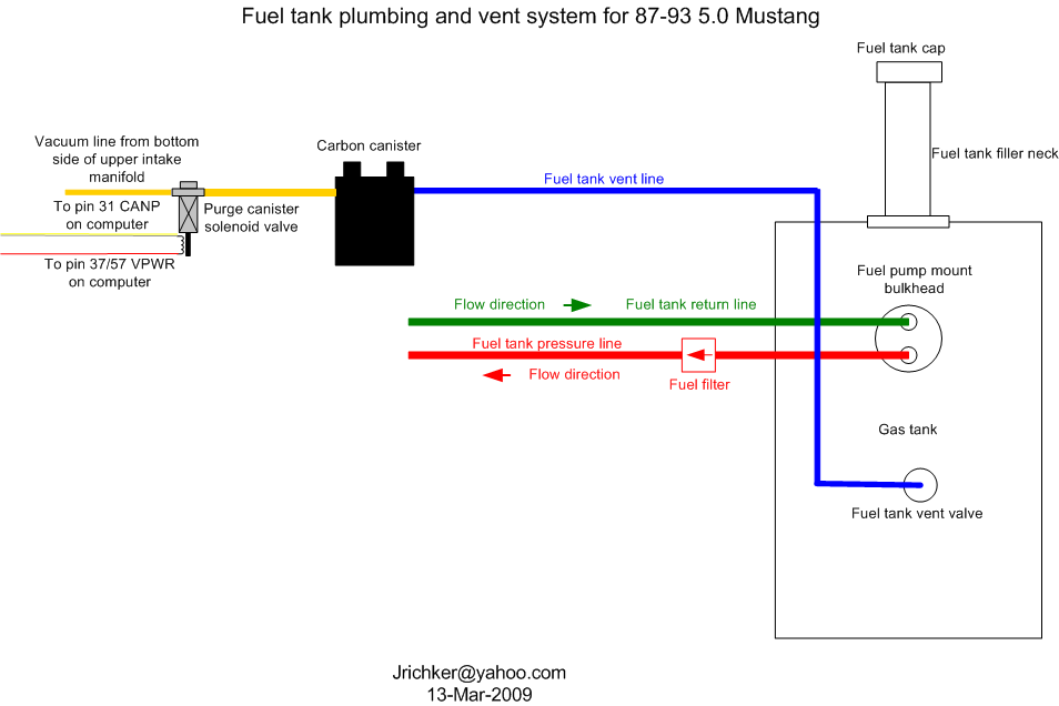
Charcoal canister plumbing - one 3/8" tube from the bottom of the upper manifold to the rubber hose. Rubber hose connects to one side of the canister solenoid valve. Other side of the solenoid valve connects to one side of the canister. The other side of the canister connects to a rubber hose that connects to a line that goes all the way back to the gas tank. There is an electrical connector coming from the passenger side injector harness near #1 injector that plugs into the canister solenoid valve. It's purpose is to vent the gas tank. The solenoid valve opens at cruse to provide some extra fuel. The canister is normally mounted on the passenger side frame rail near the smog pump pulley.
attachment.php


It does not weigh but a pound or so and helps richen up the cruse mixture. It draws no HP & keeps the car from smelling like gasoline in a closed garage. So with all these good things and no bad ones, why not hook it up & use it?


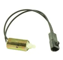
The purge valve solenoid connector is a dangling wire that is near the ECT sensor and oil filler on the passenger side rocker cover. The actual solenoid valve is down next to the carbon canister. There is about 12"-16" of wire that runs parallel to the canister vent hose that comes off the bottom side of the upper intake manifold. That hose connects one port of the solenoid valve; the other port connects to the carbon canister.

The purge valve solenoid should be available at your local auto parts store.

Purge valve solenoid:
6


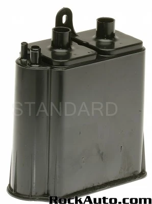
The carbon canister is normally mounted on the passenger side frame rail near the smog pump pulley.
Carbon Canister:
CP2000photo%20primary__ra_p.jpg
 

Attachments

  • attachment.php?attachmentid=51122&d=1183977187.gif
    attachment.php?attachmentid=51122&d=1183977187.gif
    16.9 KB · Views: 228
Last edited:
Here goes the bad news...

I suggest that you print this post out and have it handy when you do the testing & troubleshooting work.

Fix the code 22 first; see the code 22 the test path below.


Then pull the spark plug from #8 cylinder; it is the driver side rear spark plug.
The cylinder balance test pointed to it as being non functional. Check the spark plug for fouling or damage, then use an ohmmeter to check the resistance of the spark plug wire. It should be between 2000-8000 ohms, less is OK, much more than those numbers in not good. Check the spark plug wire and distributor cap for jumping spark, cracks or burned spots. If the spark plug, distributor cap and spark plug wire are all good,then do a compression test. Most auto parts stores will rent or loan a compression tester if you have a credit card or make a cash deposit. If the spark plug, spark plug wire, distributor cap and compression test are all good, then the fuel injector and wiring are suspect. I will help that that problem if it is needed after you have eliminated everything else that I have named.

The rest of your codes are emission related. Someone removed, disconnected or disabled the emissions equipment in an effort to make the car faster. That DOES NOT WORK!!!! All it does is to make the computer to spit codes and cause other problems. All the emissions equipment shuts off when you go WOT (Wide Open Throttle) and does not negatively affect performance to any great extent.


MAP/BARO sensor operation and code 22

Revised 14-Nov-2014 to add wire colors for frequency & voltage testing and engine sensor wiring diagrams.

On a Speed Density car, the MAP/BARO sensor is connected to the intake manifold and acts to sense the manifold pressure. Lower vacuum inside the intake manifold when combined with more throttle opening measured by the TPS means more airflow through the engine. As airflow increases, fuel flow through the injectors needs to increase to keep the air/fuel ratio where it needs to be. When manifold vacuum increases, the engine is either decelerating or idling, and it needs to reduce the fuel flow through the injectors.

On a Mass Air car, the MAP/BARO sensor vents to open air and actually senses the barometric pressure due to changes in weather and altitude. Its purpose is to set a baseline for the computer to know the barometric pressure. As barometric pressure decreases, it leans out the fuel flow to compensate for less oxygen in the air. When the barometric pressure rises, it increases to add fuel since there is more oxygen in the air. The fuel requirements decrease as altitude increases, since the atmospheric pressure decreases.

Disconnecting the MAP or BARO sensor will set code 22.

Misconnecting the BARO sensor to vacuum on a Mass Air car will cause the computer to lean out the fuel mixture.

Code 22 or 126 MAP (vacuum) or BARO signal out of range. The MAP or BARO sensor is pretty much the same sensor for both Mass Air & Speed Density cars. The main difference is where it is connected. Mass Air cars vent it to the atmosphere, while Speed Density cars connect it to the intake manifold vacuum. Its purpose is to help set a baseline for the air/fuel mixture by sensing changes in barometric pressure. The MAP or BAP sensor puts out a 5 volt square wave that changes frequency with variations in atmospheric pressure. The base is 154 HZ at 29.92" of mercury - dry sunny day at sea level, about 68-72 degrees. You need an oscilloscope or frequency meter to measure it. There a very few DVM’s with a price tag under $40 that will measure frequency, but there are some out there.

Map sensor wiring:
black/white - ground
orange/white or +5 volts power
white/red signal out.

Measure the +5 volt supply using the orange/white and black/white wires
Measure the signal using the black/white and white/red wires.

The MAP/BARO sensor is mounted on the firewall behind the upper manifold on 86-93 Mustangs.

Baro or MAP test using a real frequency meter - run the test key on, engine off. The noise from the ignition system will likely upset the frequency meter. I used a 10 x oscilloscope probe connected from the frequency meter to the MAP/BAP to reduce the jitter in the meter's readout. And oscilloscope is very useful if you have access to one or know of someone who does. With an oscilloscope, you can see the waveform and amplitude.

If it is defective, your air/fuel ratio will be off and the car’s performance & emissions will suffer

Some basic checks you can make to be sure that the sensor is getting power & ground:
Note that all resistance tests must be done with power off. Measuring resistance with a circuit powered on will give false readings and possibly damage the meter.
Check the resistance between the black/white wire on the MAP/BARO sensor and then the black/white wire on the EGR and the same wire on the TPS. It should be less than 1 ohm. Next check the resistance between the black/white wire and the negative battery cable. It should be less than 1.5 ohm.

The following power on check requires you to turn the ignition switch to the Run position.
Use a DVM to check for 5 volts on the orange/white wire. If it is missing, look for +5 volts at the orange/white wire on the TPS or EGR sensors. Use the black/white wire for the ground for the DVM.

a9x-series-computer-connector-wire-side-view-gif.71316.gif


eec-iv-computer-connector-for-5-0-mustang-gif.88243.gif


Diagrams courtesy of Tmoss & Stang&2birds

Complete computer, actuator & sensor wiring diagram for 88-91 Mass Air Mustangs
88-91_5.0_EEC_Wiring_Diagram.gif


Complete computer, actuator & sensor wiring diagram for 91-93 Mass Air Mustangs
91-93_5.0_EEC_Wiring_Diagram.gif


See the following website for some help from Tmoss (diagram designer) & Stang&2Birds (website host) for help on 88-95 wiring http://www.veryuseful.com/mustang/tech/engine/ Everyone should bookmark this site.

Complete computer, actuator & sensor wiring diagram for 91-93 Mass Air Mustangs
http://www.veryuseful.com/mustang/tech/engine/images/91-93_5.0_EEC_Wiring_Diagram.gif

Complete computer, actuator & sensor wiring diagram for 88-91 Mass Air Mustangs
http://www.veryuseful.com/mustang/tech/engine/images/88-91_5.0_EEC_Wiring_Diagram.gif

Ignition switch wiring
http://www.veryuseful.com/mustang/tech/engine/images/IgnitionSwitchWiring.gif

Fuel, alternator, A/C and ignition wiring
http://www.veryuseful.com/mustang/tech/engine/images/fuel-alt-links-ign-ac.gif

O2 sensor wiring harness
http://www.veryuseful.com/mustang/tech/engine/images/mustangO2Harness.gif

Vacuum diagram 89-93 Mustangs
http://www.veryuseful.com/mustang/tech/engine/images/mustangFoxFordVacuumDiagram.jpg

HVAC vacuum diagram
http://www.veryuseful.com/mustang/tech/engine/images/Mustang_AC_heat_vacuum_controls.gif

TFI module differences & pin out
http://www.veryuseful.com/mustang/tech/engine/images/TFI_5.0_comparison.gif

Fuse box layout
http://www.veryuseful.com/mustang/tech/engine/images/MustangFuseBox.gif

87-92 power window wiring
http://www.veryuseful.com/mustang/tech/engine/images/mustang87-92 PowerWindowWiring.gif

93 power window wiring
http://www.veryuseful.com/mustang/tech/engine/images/mustang93PowerWindows.gif

T5 Cutaway showing T5 internal parts
http://www.veryuseful.com/mustang/tech/engine/images/5_Speed_Cutaway_Illustrated.jpg

Visual comparison of the Ford Fuel Injectors, picture by TMoss:
http://www.veryuseful.com/mustang/tech/engine/images/Ford_Injector_Guide.jpg


Code 12 -Idle Air Bypass motor not controlling idle properly (generally idle too low) - IAB dirty or not working. Clean the electrical contacts with non flammable brake parts cleaner at the same time.

IAC doesn't work: look for +12 volts at the IAC red wire. Then check for continuity between the white/lt blue wire and pin 21 on the computer. The IAC connector contacts will sometimes corrode and make the IAC not work. The red wire on the IAC is always hot with the engine in run mode. The computer provides a ground for the current for the IAC. It switches the ground on and off, making a square wave with a varying duty cycle. A normal square wave would be on for 50% of the time and off for 50% of the time. When the idle speed is low, the duty cycle increases more than 50% to open the IAC more. When the engine speed is high, it decreases the duty cycle to less than 50% to close the IAC. An old-fashioned dwell meter can be used to check the change: I haven’t tried it personally, but it should work. In theory, it should read ½ scale of whatever range you set it on with a 50% duty cycle. An Oscilloscope is even better if you can find someone who has one and will help.

attachment.php?attachmentid=58887&stc=1&d=1247241098.gif


Recommended procedure for cleaning the IAC/IAB:
Conventional cleaning methods like throttle body cleaner aren’t very effective. The best method is a soak type cleaner used for carburetors. If you are into fixing motorcycles, jet skis, snowmobiles or anything else with a small carburetor, you probably have used the one gallon soak cleaners like Gunk or Berryman. One of the two should be available at your local auto parts store for $22-$29. Take the solenoid off the body and set it aside: the carb cleaner will damage some types of plastic parts. Soak the metal body in the carb cleaner overnight. There is a basket to set the parts in while they are soaking. When you finish soaking overnight, twist the stem of the IAB/IAC that sticks out while the blocker valve is seated. This removes any leftover deposits from the blocker valve seat. Rinse the part off with water and blow it dry with compressed air. The IAC/IAB should seal up nicely now. Once it has dried, try blowing through the bottom hole and it should block the air flow. Reassemble and reinstall to check it out.

Gunk Dip type carb & parts soaker:
21hb0QWbOeL._SL500_AA300_.webp


Setting the base idle speed:
First of all, the idle needs to be adjusted to where the speed is at or below 600 RPM with the IAC disconnected. If you have a wild cam, you may have to raise this figure 100-150 RPM or so. Then the electrical signal through the IAC can vary the airflow through it under computer control. Remember that the IAC can only add air to increase the base idle speed set by the mechanical adjustment. The 600 RPM base idle speed is what you have after the mechanical adjustment. The IAC increases that speed by supplying more air under computer control to raise the RPM’s to 650-725 RPM’s. This figure will increase if you have a wild cam, and may end up between 800-950 RPM

Remember that changing the mechanical idle speed adjustment changes the TPS setting too.

This isn't the method Ford uses, but it does work. Do not attempt to set the idle speed until you have fixed all the codes and are sure that there are no vacuum leaks.

Disconnect the battery negative terminal and turn the headlights on. Leave the battery negative terminal disconnected for 5 minutes or so. Then turn the headlights off and reconnect the battery. This erases the computer settings that may affect idle performance.

Warm the engine up to operating temperature, place the transmission in neutral, and set the parking brake. Turn off lights, A/C, all unnecessary electrical loads. Disconnect the IAC electrical connector. Remove the SPOUT plug. This will lock the ignition timing so that the computer won't change the spark advance, which changes the idle speed. Note the engine RPM: use the mechanical adjustment screw under the throttle body to raise or lower the RPM until you get the 600 RPM mark +/- 25 RPM. A wild cam may make it necessary to increase the 600 RPM figure to 700 RPM or possibly a little more to get a stable idle speed.
Changing the mechanical adjustment changes the TPS, so you will need to set it.

When you are satisfied with the results, turn off the engine, and re-install the SPOUT and reconnect the IAC. The engine should idle with the range of 650-750 RPM without the A/C on or extra electrical loads. A wild cam may make this figure somewhat higher.

An engine that whose idle speed cannot be set at 600 RPM with the IAC disconnected has mechanical problems. Vacuum leaks are the #1 suspect in this case. A vacuum gauge will help pinpoint both vacuum leaks and improperly adjusted valves. A sticking valve or one adjusted too tight will cause low vacuum and a 5"-8" sweep every time the bad cylinder comes up on compression stroke. An extreme cam can make the 600 RPM set point difficult to set. Contact your cam supplier or manufacturer to get information on idle speed and quality


Code 33 - Insufficient EGR flow detected.
Look for vacuum leaks, cracked vacuum lines, failed EGR vacuum regulator. Check to see if you have 10” of vacuum at the EGR vacuum connection coming from the intake manifold. Look for electrical signal at the vacuum regulator solenoid valves located on the rear of the passenger side wheel well. Using a test light across the electrical connector, it should flicker as the electrical signal changes. Remember that the computer does not source any power, but provides the ground necessary to complete the circuit. That means one side of the circuit will always be hot, and the other side will go to ground or below 1 volt as the computer switches on that circuit.
Check for resistance between the brown/lt green wire on the EGR sensor and pin 27 on the computer: you should have less than 1.5 ohm.

Backside view of the computer wiring connector:
a9x-series-computer-connector-wire-side-view-gif.71316.gif


See the following website for some help from Tmoss (diagram designer) & Stang&2Birds (website host)

http://www.veryuseful.com/mustang/tech/engine/images/fuel-alt-links-ign-ac.gif

http://www.veryuseful.com/mustang/tech/engine/images/88-91eecPinout.gif


EGR test procedure courtesy of cjones

to check the EGR valve:
bring the engine to normal temp.

connect a vacuum pump to the EGR Valve or see the EGR test jig drawing below. Connnect the test jig or to directly to manifold vacuum.

Do not connect the EGR test jig to the EVR (Electronic Vacuum Regulator).


apply 5in vacuum to the valve. Using the test jig, use your finger to vary the vacuum

if engine stumbled or died then EGR Valve and passage(there is a passageway through the heads and intake) are good.

if engine did NOT stumble or die then either the EGR Valve is bad and/or the passage is blocked.

if engine stumbled, connect EGR test jig to the hose coming off of the EGR Valve.
Use your finger to cap the open port on the vacuum tee.
snap throttle to 2500 RPM (remember snap the throttle don't hold it there).
did the vacuum gauge show about 2-5 in vacuum?
if not the EVR has failed

EGR test jig
egr-test-jig-gif.58022.gif


The operation of the EGR vacuum regulator can be checked by using a test light applied across the wiring connector. Jumper the computer into self test mode and turn the key on but do not start the engine. You will hear all the actuators (including the EVR vacuum regulator) cycle. Watch for the light to flicker: that means the computer has signaled the EGR vacuum regulator successfully.


Codes 44 & 94 - AIR system inoperative - Air Injection. Check vacuum lines for leaks, & cracks. Check for a clogged air crossover tube, where one or both sides of the tube clog with carbon.

attachment.php?attachmentid=50636&d=1180923382.gif


Revised 21 Sep 2012 to correct the description of the process that sets the code and include Thermactor Air System diagram.

If you have a catalytic converter H pipe, you need to fix these codes. If you don't, then don't worry about them.

Code 44 RH side air not functioning.
Code 94 LH side air not functioning.

The TAD solenoid/TAD diverter valve directs smog pump output to either the crossover tube attached to the cylinder heads or to the catalytic converters.

The O2 sensors are placed before the catalytic converters, so they do not see the extra O2 when the smog pump's output is directed to the converters or the input just before the converter.

The 44/94 code uses the O2 sensors to detect a shift in the O2 level in the exhaust. The smog pump provides extra air to the exhaust which raises the O2 level in the exhaust when the smog pump output is directed through the crossover tube.

When there is an absence of increase in the O2 levels when the TAD solenoid/TAD diverter valve directs air through the crossover tube, it detects the lower O2 level and sets the code.

Failure mode is usually due to a clogged air crossover tube, where one or both sides of the tube clog with carbon. The air crossover tube mounts on the back of the cylinder heads and supplies air to each of the Thermactor air passages cast into the cylinder heads. When the heads do not get the proper air delivery, they set codes 44 & 94, depending on which passage is clogged. It is possible to get both 44 & 94, which would suggest that the air pump or control valves are not working correctly, or the crossover tube is full of carbon or missing.

Testing the system:
Note that the engine must be running to do the tests unless stated otherwise. For safety’s sake, do test preparation like loosening clamps, disconnecting hoses and connecting things to a vacuum source with the engine off.


Disconnect the big hose from smog pump: with the engine running you should feel air output. Reconnect the smog pump hose & apply vacuum to the first vacuum controlled valve: Its purpose is to either dump the pump's output to the atmosphere or pass it to the next valve.

The next vacuum controlled valve directs the air to either the cylinder heads when the engine is cold or to the catalytic converter when the engine is warm. Disconnect the big hoses from the back side of the vacuum controlled valve and start the engine. Apply vacuum to the valve and see if the airflow changes from one hose to the next.

The two electrical controlled vacuum valves mounted on the rear of the passenger side wheel well turn the vacuum on & off under computer control. Check to see that both valves have +12 volts on the red wire. Then ground the white/red wire and the first solenoid should open and pass vacuum. Do the same thing to the light green/black wire on the second solenoid and it should open and pass vacuum.

Remember that the computer does not source power for any actuator or relay, but provides the ground necessary to complete the circuit. That means one side of the circuit will always be hot, and the other side will go to ground or below 1 volt as the computer switches on that circuit.

The following computer tests are done with the engine not running.
The computer provides the ground to complete the circuit to power the solenoid valve that turns the
vacuum on or off. The computer is located under the passenger side kick panel. Remove the kick panel & the cover over the computer wiring connector pins. Check Pin 38 Solenoid valve #1 that provides vacuum to the first Thermactor control valve for a switch from 12-14 volts to 1 volt or less. Do the same with pin 32 solenoid valve #2 that provides vacuum to the second Thermactor control valve. Turning the ignition to Run with the computer jumpered to self-test mode will cause all the actuators to toggle on and off. If after doing this and you see no switching of the voltage on and off, you can start testing the wiring for shorts to ground and broken wiring. An Ohm check to ground with the computer connector disconnected & the solenoid valves disconnected should show open circuit between the pin 32 and ground and again on pin 38 and ground. In like manner, there should be less than 1 ohm between pin 32 and solenoid valve #2 and pin 38 & Solenoid valve #1.

The following computer tests are done with the engine running.
If after checking the resistance of the wiring & you are sure that there are no wiring faults, start looking at the solenoid valves. If you disconnect them, you can jumper power & ground to them to verify operation with the engine running. Power & ground supplied should turn on the vacuum flow, remove either one and the vacuum should stop flowing.

Typical resistance of the solenoid valves is in the range of 20-70 Ohms.

See the following website for some help from Tmoss (diagram designer) & Stang&2Birds (website host)

http://www.veryuseful.com/mustang/tech/engine/images/fuel-alt-links-ign-ac.gif

http://www.veryuseful.com/mustang/tech/engine/images/88-91eecPinout.gif

If you have a catalytic converter H pipe, you need to fix these codes. If you don't, then don't worry about them

Code 85 CANP solenoid - The Carbon Canister solenoid is inoperative or missing.

Revised 11 –Jan_2015 to add warning about vacuum leaks due to deteriorated hose or missing caps on vacuum lines when the solenoid is removed.

Check vacuum lines for leaks and cracks. Check electrical wiring for loose connections, damaged wiring and insulation. Check solenoid valve operation by grounding the gray/yellow wire to the solenoid and blowing through it.
The computer provides the ground for the solenoid. The red wire to the solenoid is always energized any time the ignition switch is in the run position.

If you disconnected the carbon canister and failed to properly cap the vacuum line coming from under the upper intake manifold, you will have problems. You will also have problems if the remaining hose coming from under the upper intake manifold or caps for the vacuum line are sucking air.

Charcoal canister plumbing - one 3/8" tube from the bottom of the upper manifold to the rubber hose. Rubber hose connects to one side of the canister solenoid valve. Other side of the solenoid valve connects to one side of the canister. The other side of the canister connects to a rubber hose that connects to a line that goes all the way back to the gas tank. There is an electrical connector coming from the passenger side injector harness near #1 injector that plugs into the canister solenoid valve. It's purpose is to vent the gas tank. The solenoid valve opens at cruse to provide some extra fuel. The canister is normally mounted on the passenger side frame rail near the smog pump pulley.

attachment.php?attachmentid=58191&stc=1&d=1241921055.gif


It does not weigh but a pound or so and helps richen up the cruse mixture. It draws no HP & keeps the car from smelling like gasoline in a closed garage. So with all these good things and no bad ones, why not hook it up & use it?


The purge valve solenoid connector is a dangling wire that is near the ECT sensor and oil filler on the passenger side rocker cover. The actual solenoid valve is down next to the carbon canister. There is about 12"-16" of wire that runs parallel to the canister vent hose that comes off the bottom side of the upper intake manifold. That hose connects one port of the solenoid valve; the other port connects to the carbon canister.

The purge valve solenoid should be available at your local auto parts store.

Purge valve solenoid:
6.webp


The carbon canister is normally mounted on the passenger side frame rail near the smog pump pulley.
Carbon Canister:
CP2000photo%20primary__ra_p.webp
 
.
how much do you think a shop would charge to fix this problem lol thank you for all your help its appreciated

I don't know. I help Mustang enthusiasts and not repair shops.
What I do here I do for free to help Mustang owners enjoy their cars, and not to put money in some repair shop's cash register.
 
We did not 22 yet will work on it tonight
Some extra input on replacing sensors: you must clear the codes anytime you replace any sensor.

How to clear codes.
Clear the computer codes by disconnecting the battery negative terminal and turn the headlights on. That clears the computer's memory of codes and the adaptive learning data it generates from sensors.Turn the headlights off and reconnect the all sensors including the MAF and anything else you may have disconnected. Then reconnect the battery negative cable.. This clears all spurious codes that may have been generated while troubleshooting problems. This does not fix the code problems, it just gives you a clean slate to start recording what the computer sees happening.

Run the car for at least 30 minutes of driving and dump the codes again to assure that you have fixed the code problem or sensor problem