
Ok so I've done all I can to make this run good so 89 roller motor 87 injection system mass air conversion I installed a9p pcm the codes are 34 67 85 95 these are the ones that stay with the car I've had a few pcms through now but same codes all though the car runs pretty good still a rough idle so any help would be appreciated by the way this all in a 65 thanks
You are using an out of date browser. It may not display this or other websites correctly.
You should upgrade or use an alternative browser.
You should upgrade or use an alternative browser.
5.0 Codes
- Thread starter Lourdalfe
- Start date
I moved this to the 5.0 tech, your more likely to get some help here, they will ask some questions like are you using o2's and did you use stock fox wiring, stuff like that.
Code 34 Or 334 - EGR voltage above closed limit –
Revised 26-Sep-2011 to add EGR cleaning and movement test for pintle when vacuum is applied to diaphragm
Failed sensor, carbon between EGR pintle valve and seat holding the valve off its seat. Remove the EGR valve and clean it with carbon remover. Prior to re-installing see if you can blow air through the flange side of the EGR by mouth. If it leaks, there is carbon stuck on the pintle valve seat clean or, replace the EGR valve ($85-$95).
Recommended procedure for cleaning the EGR:
Conventional cleaning methods like throttle body cleaner aren’t very effective. The best method is a soak type cleaner used for carburetors. If you are into fixing motorcycles, jet skis, snowmobiles or anything else with a small carburetor, you probably have used the one gallon soak cleaners like Gunk or Berryman. One of the two should be available at your local auto parts store for $22-$29. There is a basket to set the parts in while they are soaking. Soak the metal body in the carb cleaner overnight. Don’t immerse the diaphragm side, since the carb cleaner may damage the diaphragm. If you get any of the carb cleaner on the diaphragm, rinse it off with water immediately. Rinse the part off with water and blow it dry with compressed air. Once it has dried, try blowing through the either hole and it should block the air flow. Do not put parts with water on them or in them in the carb cleaner. If you do, it will weaken the carb cleaner and it won’t clean as effectively.
Gunk Dip type carb & parts soaker:

If you have a handy vacuum source, apply it to the diaphragm and watch to see if the pintle moves freely. Try blowing air through either side and make sure it flows when the pintle retracts and blocks when the pintle is seated. If it does not, replace the EGR.
If the blow by test passes, and you have replaced the sensor, then you have electrical ground problems. Check the resistance between the black/white wire on the MAP/BARO sensor and then the black/white wire on the EGR and the same wire on the TPS. It should be less than 1.5 ohm. Next check the resistance between the black/white wire and the negative battery post. It should be less than 1.5 ohm.
Note that all resistance tests must be done with power off. Measuring resistance with a circuit powered on will give false readings and possibly damage the meter.
Let’s put on our Inspector Gadget propeller head beanies and think about how this works:
The EGR sensor is a variable resistor with ground on one leg and Vref (5 volts) on the other. Its’ resistance ranges from 4000 to 5500 Ohms measured between Vref & ground, depending on the sensor. The center connection of the variable resistor is the slider that moves in response to the amount of vacuum applied. The slider has some minimum value of resistance greater than 100 ohms so that the computer always sees a voltage present at its’ input. If the value was 0 ohms, there would be no voltage output. Then the computer would not be able to distinguish between a properly functioning sensor and one that had a broken wire or bad connection. The EGR I have in hand reads 700 Ohms between the slider (EPV) and ground (SIG RTN) at rest with no vacuum applied. The EGR valve or sensor may cause the voltage to be above closed limits due to the manufacturing tolerances that cause the EGR sensor to rest at a higher position than it should.
The following sensors are connected to the white 10 pin connector (salt & pepper engine harness connectors)

This will affect idle quality by diluting the intake air charge
Code 67
Revised 18-Mar-2017 to include warning about the necessity of having a 5 speed O2 Sensor wiring harness when bypassing the wiring for test purposes
Cause of problem:
Clutch not depressed (5 speed) or car not in neutral (5 speed and auto) or not in park (auto) or A/C in On position when codes where dumped. Possible neutral safety switch or wiring problem. This code will prevent you from running the Key On Engine On tests.
External evidence from other sources claims that a code 67 can cause an idle surge condition. Do try to find and fix any issues with the switch and wiring if you get a code 67.
What the NSS (Neutral Safety Switch) does:
5 speed transmission: It has no connection with the starter, and the engine can be cranked without it being connected.
Auto transmission: It is the safety interlock that prevents the starter from cranking the engine with the transmission in gear.
What it does for both 5 speed and auto transmission cars:
The computer wants to make sure the A/C is off due to the added load on the engine for the engine running computer diagnostic tests. It also checks to see that the transmission is in Neutral (5 speed and auto transmission) and the clutch depressed (T5, T56, Tremec 3550 & TKO)). This prevents the diagnostics from being run when the car is driven. Key On Engine Running test mode takes the throttle control away from the driver for several tests. This could prove hazardous if the computer was jumpered into test mode and then driven.
The following is for 5 speed cars only. Do not do this unless you are sure that you have a 5 speed O2 Sensor harness!!!! Smoke, sparks and expensive pain in the wallet may ensue if you don’t.
The NSS code 67 can be bypassed for testing. You will need to temporarily ground computer pin 30 to the chassis. Computer pin 30 uses a Lt blue/yellow wire. Remove the passenger side kick panel and then remove the plastic cover from the computer wiring connector. Use a safety pin to probe the connector from the rear. Jumper the safety pin to the ground near the computer.
Be sure to remove the jumper BEFORE attempting to drive the car!!!

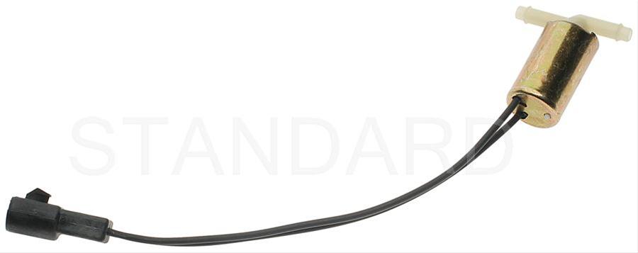
Code 85 CANP solenoid - The Carbon Canister solenoid is inoperative or missing.
Revised 11 –Jan_2015 to add warning about vacuum leaks due to deteriorated hose or missing caps on vacuum lines when the solenoid is removed.
Check vacuum lines for leaks and cracks. Check electrical wiring for loose connections, damaged wiring and insulation. Check solenoid valve operation by grounding the gray/yellow wire to the solenoid and blowing through it.
The computer provides the ground for the solenoid. The red wire to the solenoid is always energized any time the ignition switch is in the run position.
If you disconnected the carbon canister and failed to properly cap the vacuum line coming from under the upper intake manifold, you will have problems. You will also have problems if the remaining hose coming from under the upper intake manifold or caps for the vacuum line are sucking air.
Charcoal canister plumbing - one 3/8" tube from the bottom of the upper manifold to the rubber hose. Rubber hose connects to one side of the canister solenoid valve. Other side of the solenoid valve connects to one side of the canister. The other side of the canister connects to a rubber hose that connects to a line that goes all the way back to the gas tank. There is an electrical connector coming from the passenger side injector harness near #1 injector that plugs into the canister solenoid valve. It's purpose is to vent the gas tank. The solenoid valve opens at cruse to provide some extra fuel. The canister is normally mounted on the passenger side frame rail near the smog pump pulley.
Connecting the gas tank vent line directly to the intake manifold will result in fuel vapor being constantly sucked into the intake manifold. There is unmetered fuel that the computer cannot adjust for. The result is poor idle and poor fuel economy.

It does not weigh but a pound or so and helps richen up the cruse mixture. It draws no HP & keeps the car from smelling like gasoline in a closed garage. So with all these good things and no bad ones, why not hook it up & use it?
The purge valve solenoid connector is a dangling wire that is near the ECT sensor and oil filler on the passenger side rocker cover. The actual solenoid valve is down next to the carbon canister. There is about 12"-16" of wire that runs parallel to the canister vent hose that comes off the bottom side of the upper intake manifold. That hose connects one port of the solenoid valve; the other port connects to the carbon canister.
The purge valve solenoid should be available at your local auto parts store.
Purge valve solenoid:
The carbon canister is normally mounted on the passenger side frame rail near the smog pump pulley.
Carbon Canister:

Code 95 Key On, Engine not Running - the following test path is for 86-90 model Mustangs.
The 95 code is because at one time or another, the fuel pump relay hiccupped and didn't provide power the pump when the computer told it to run. Sometimes this is a one time thing, other times it is a no run or runs poorly condition.
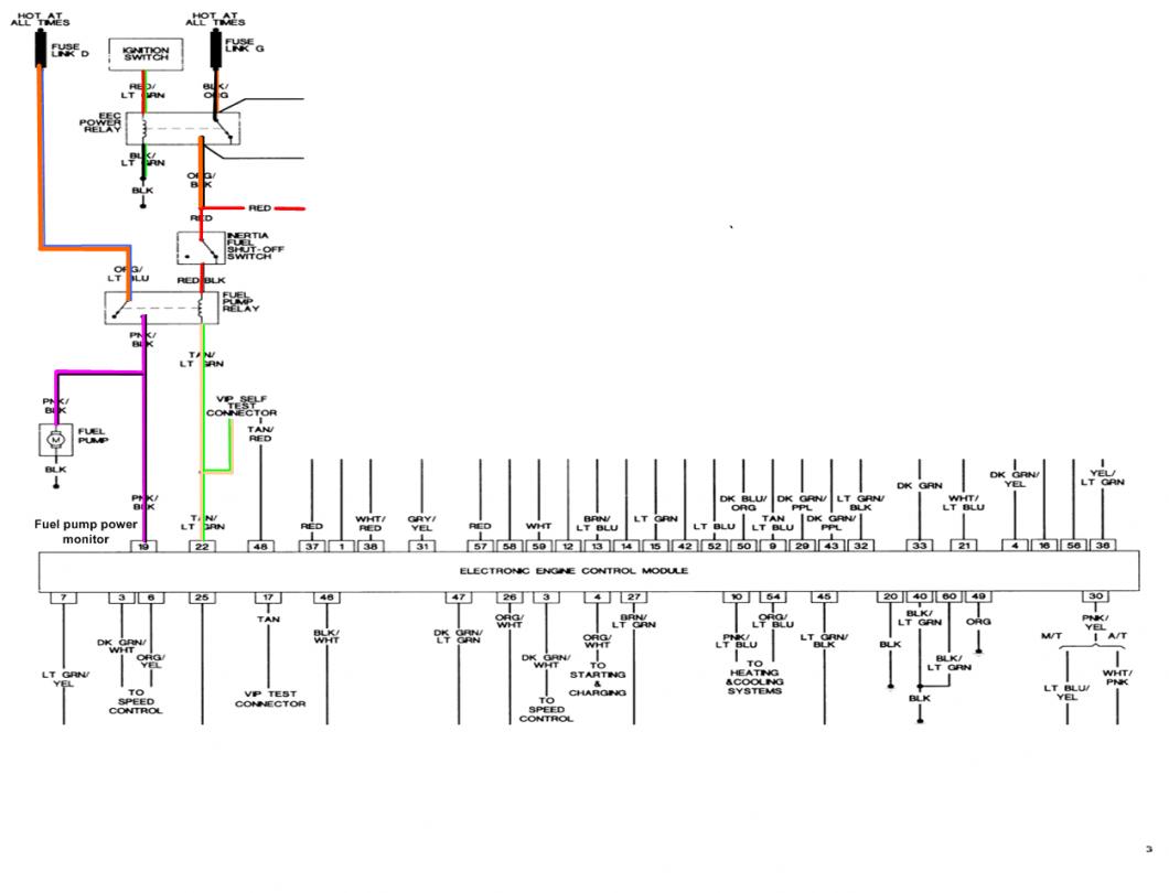
Using the diagram, check the red/black wire from the fuel pump relay: you should see 12 volts or so. If not, check the inertia switch: on a hatch it is on the driver’s side by the taillight. Look for a black rubber plug that pops out: if you don't find it, then loosen up the plastic trim. Check for voltage on both sides of the switch. If there is voltage on both sides, then check the Pink/black wire on the fuel pump relay: it is the power feed to the fuel pump. No voltage there, check the Orange/Lt blue wire, it is the power feed to the fuel pump relay & has a fuse link in it. If there is good voltage there & at the Pink/black wire, swap the relay.
Some Mass Air conversions neglect to run the extra fuel pump wire, and they always have a 95 code. See http://www.stangnet.com/tech/maf/massairconversion.html for more information on the Mass Air wiring conversion.
See the following website for some help from Tmoss (diagram designer) & Stang&2Birds (website host) for help on 88-95 wiring http://www.veryuseful.com/mustang/tech/engine/ Everyone should bookmark this site.
Ignition switch wiring
http://www.veryuseful.com/mustang/tech/engine/images/IgnitionSwitchWiring.gif
Fuel, alternator, A/C and ignition wiring
http://www.veryuseful.com/mustang/tech/engine/images/fuel-alt-links-ign-ac.gif
Complete computer, actuator & sensor wiring diagram for 88-91 Mass Air Mustangs
http://www.veryuseful.com/mustang/tech/engine/images/88-91_5.0_EEC_Wiring_Diagram.gif
Complete computer, actuator & sensor wiring diagram for 91-93 Mass Air Mustangs
http://www.veryuseful.com/mustang/tech/engine/images/91-93_5.0_EEC_Wiring_Diagram.gif
Vacuum diagram 89-93 Mustangs
http://www.veryuseful.com/mustang/tech/engine/images/mustangFoxFordVacuumDiagram.jpg
HVAC vacuum diagram
http://www.veryuseful.com/mustang/tech/engine/images/Mustang_AC_heat_vacuum_controls.gif
TFI module differences & pinout
http://www.veryuseful.com/mustang/tech/engine/images/TFI_5.0_comparison.gif
Fuse box layout
http://www.veryuseful.com/mustang/tech/engine/images/MustangFuseBox.gif
Revised 26-Sep-2011 to add EGR cleaning and movement test for pintle when vacuum is applied to diaphragm
Failed sensor, carbon between EGR pintle valve and seat holding the valve off its seat. Remove the EGR valve and clean it with carbon remover. Prior to re-installing see if you can blow air through the flange side of the EGR by mouth. If it leaks, there is carbon stuck on the pintle valve seat clean or, replace the EGR valve ($85-$95).
Recommended procedure for cleaning the EGR:
Conventional cleaning methods like throttle body cleaner aren’t very effective. The best method is a soak type cleaner used for carburetors. If you are into fixing motorcycles, jet skis, snowmobiles or anything else with a small carburetor, you probably have used the one gallon soak cleaners like Gunk or Berryman. One of the two should be available at your local auto parts store for $22-$29. There is a basket to set the parts in while they are soaking. Soak the metal body in the carb cleaner overnight. Don’t immerse the diaphragm side, since the carb cleaner may damage the diaphragm. If you get any of the carb cleaner on the diaphragm, rinse it off with water immediately. Rinse the part off with water and blow it dry with compressed air. Once it has dried, try blowing through the either hole and it should block the air flow. Do not put parts with water on them or in them in the carb cleaner. If you do, it will weaken the carb cleaner and it won’t clean as effectively.
Gunk Dip type carb & parts soaker:
If you have a handy vacuum source, apply it to the diaphragm and watch to see if the pintle moves freely. Try blowing air through either side and make sure it flows when the pintle retracts and blocks when the pintle is seated. If it does not, replace the EGR.
If the blow by test passes, and you have replaced the sensor, then you have electrical ground problems. Check the resistance between the black/white wire on the MAP/BARO sensor and then the black/white wire on the EGR and the same wire on the TPS. It should be less than 1.5 ohm. Next check the resistance between the black/white wire and the negative battery post. It should be less than 1.5 ohm.
Note that all resistance tests must be done with power off. Measuring resistance with a circuit powered on will give false readings and possibly damage the meter.
Let’s put on our Inspector Gadget propeller head beanies and think about how this works:
The EGR sensor is a variable resistor with ground on one leg and Vref (5 volts) on the other. Its’ resistance ranges from 4000 to 5500 Ohms measured between Vref & ground, depending on the sensor. The center connection of the variable resistor is the slider that moves in response to the amount of vacuum applied. The slider has some minimum value of resistance greater than 100 ohms so that the computer always sees a voltage present at its’ input. If the value was 0 ohms, there would be no voltage output. Then the computer would not be able to distinguish between a properly functioning sensor and one that had a broken wire or bad connection. The EGR I have in hand reads 700 Ohms between the slider (EPV) and ground (SIG RTN) at rest with no vacuum applied. The EGR valve or sensor may cause the voltage to be above closed limits due to the manufacturing tolerances that cause the EGR sensor to rest at a higher position than it should.
The following sensors are connected to the white 10 pin connector (salt & pepper engine harness connectors)
This will affect idle quality by diluting the intake air charge
Code 67
Revised 18-Mar-2017 to include warning about the necessity of having a 5 speed O2 Sensor wiring harness when bypassing the wiring for test purposes
Cause of problem:
Clutch not depressed (5 speed) or car not in neutral (5 speed and auto) or not in park (auto) or A/C in On position when codes where dumped. Possible neutral safety switch or wiring problem. This code will prevent you from running the Key On Engine On tests.
External evidence from other sources claims that a code 67 can cause an idle surge condition. Do try to find and fix any issues with the switch and wiring if you get a code 67.
What the NSS (Neutral Safety Switch) does:
5 speed transmission: It has no connection with the starter, and the engine can be cranked without it being connected.
Auto transmission: It is the safety interlock that prevents the starter from cranking the engine with the transmission in gear.
What it does for both 5 speed and auto transmission cars:
The computer wants to make sure the A/C is off due to the added load on the engine for the engine running computer diagnostic tests. It also checks to see that the transmission is in Neutral (5 speed and auto transmission) and the clutch depressed (T5, T56, Tremec 3550 & TKO)). This prevents the diagnostics from being run when the car is driven. Key On Engine Running test mode takes the throttle control away from the driver for several tests. This could prove hazardous if the computer was jumpered into test mode and then driven.
The following is for 5 speed cars only. Do not do this unless you are sure that you have a 5 speed O2 Sensor harness!!!! Smoke, sparks and expensive pain in the wallet may ensue if you don’t.
The NSS code 67 can be bypassed for testing. You will need to temporarily ground computer pin 30 to the chassis. Computer pin 30 uses a Lt blue/yellow wire. Remove the passenger side kick panel and then remove the plastic cover from the computer wiring connector. Use a safety pin to probe the connector from the rear. Jumper the safety pin to the ground near the computer.
Be sure to remove the jumper BEFORE attempting to drive the car!!!
Code 85 CANP solenoid - The Carbon Canister solenoid is inoperative or missing.
Revised 11 –Jan_2015 to add warning about vacuum leaks due to deteriorated hose or missing caps on vacuum lines when the solenoid is removed.
Check vacuum lines for leaks and cracks. Check electrical wiring for loose connections, damaged wiring and insulation. Check solenoid valve operation by grounding the gray/yellow wire to the solenoid and blowing through it.
The computer provides the ground for the solenoid. The red wire to the solenoid is always energized any time the ignition switch is in the run position.
If you disconnected the carbon canister and failed to properly cap the vacuum line coming from under the upper intake manifold, you will have problems. You will also have problems if the remaining hose coming from under the upper intake manifold or caps for the vacuum line are sucking air.
Charcoal canister plumbing - one 3/8" tube from the bottom of the upper manifold to the rubber hose. Rubber hose connects to one side of the canister solenoid valve. Other side of the solenoid valve connects to one side of the canister. The other side of the canister connects to a rubber hose that connects to a line that goes all the way back to the gas tank. There is an electrical connector coming from the passenger side injector harness near #1 injector that plugs into the canister solenoid valve. It's purpose is to vent the gas tank. The solenoid valve opens at cruse to provide some extra fuel. The canister is normally mounted on the passenger side frame rail near the smog pump pulley.
Connecting the gas tank vent line directly to the intake manifold will result in fuel vapor being constantly sucked into the intake manifold. There is unmetered fuel that the computer cannot adjust for. The result is poor idle and poor fuel economy.
It does not weigh but a pound or so and helps richen up the cruse mixture. It draws no HP & keeps the car from smelling like gasoline in a closed garage. So with all these good things and no bad ones, why not hook it up & use it?
The purge valve solenoid connector is a dangling wire that is near the ECT sensor and oil filler on the passenger side rocker cover. The actual solenoid valve is down next to the carbon canister. There is about 12"-16" of wire that runs parallel to the canister vent hose that comes off the bottom side of the upper intake manifold. That hose connects one port of the solenoid valve; the other port connects to the carbon canister.
The purge valve solenoid should be available at your local auto parts store.
Purge valve solenoid:
The carbon canister is normally mounted on the passenger side frame rail near the smog pump pulley.
Carbon Canister:
Code 95 Key On, Engine not Running - the following test path is for 86-90 model Mustangs.
The 95 code is because at one time or another, the fuel pump relay hiccupped and didn't provide power the pump when the computer told it to run. Sometimes this is a one time thing, other times it is a no run or runs poorly condition.
Using the diagram, check the red/black wire from the fuel pump relay: you should see 12 volts or so. If not, check the inertia switch: on a hatch it is on the driver’s side by the taillight. Look for a black rubber plug that pops out: if you don't find it, then loosen up the plastic trim. Check for voltage on both sides of the switch. If there is voltage on both sides, then check the Pink/black wire on the fuel pump relay: it is the power feed to the fuel pump. No voltage there, check the Orange/Lt blue wire, it is the power feed to the fuel pump relay & has a fuse link in it. If there is good voltage there & at the Pink/black wire, swap the relay.
Some Mass Air conversions neglect to run the extra fuel pump wire, and they always have a 95 code. See http://www.stangnet.com/tech/maf/massairconversion.html for more information on the Mass Air wiring conversion.
See the following website for some help from Tmoss (diagram designer) & Stang&2Birds (website host) for help on 88-95 wiring http://www.veryuseful.com/mustang/tech/engine/ Everyone should bookmark this site.
Ignition switch wiring
http://www.veryuseful.com/mustang/tech/engine/images/IgnitionSwitchWiring.gif
Fuel, alternator, A/C and ignition wiring
http://www.veryuseful.com/mustang/tech/engine/images/fuel-alt-links-ign-ac.gif
Complete computer, actuator & sensor wiring diagram for 88-91 Mass Air Mustangs
http://www.veryuseful.com/mustang/tech/engine/images/88-91_5.0_EEC_Wiring_Diagram.gif
Complete computer, actuator & sensor wiring diagram for 91-93 Mass Air Mustangs
http://www.veryuseful.com/mustang/tech/engine/images/91-93_5.0_EEC_Wiring_Diagram.gif
Vacuum diagram 89-93 Mustangs
http://www.veryuseful.com/mustang/tech/engine/images/mustangFoxFordVacuumDiagram.jpg
HVAC vacuum diagram
http://www.veryuseful.com/mustang/tech/engine/images/Mustang_AC_heat_vacuum_controls.gif
TFI module differences & pinout
http://www.veryuseful.com/mustang/tech/engine/images/TFI_5.0_comparison.gif
Fuse box layout
http://www.veryuseful.com/mustang/tech/engine/images/MustangFuseBox.gif
Ok so no carbon can so I guess that code won't go away the 34 and 95 are the ones I think I need to fix the car has gone through two new fuel pumps for some reason I did replace the relay and the wiring is not the best at the plug so I'll replace the plug since I bought one and I'll clean the egr I think maybe the code 67 might be the a.c. cuss it did have a a.c. pump but of course because I installed all a 87 crown vic running gear into a 65 i did have a choice for a.c. at this point so to make sure everyone knows what I've done so far it's a 87 wiring harness out of a crown vic and Intake 19# injectors mass air conversion a9p pcm shorty headers and this is setting on a 89 mustang gt motor with a 91 aod tranny and a stock 89 mustang gt intank fuel pump it now runs pretty good but these codes have stayed with a few different pcms so time to get rid of as many codes as I can thanks again for all the help I've gotten here at,stangnet
Code 67 really isn't the AC. There's misc wiring that tells the ECU when the vehicle is in nuetral to adjust idle strategy. There's a plug on the clutch pedal, and one on the trans that are in parallel. You are missing one or both.
If the one on the t5 is missing, holding the clutch in while dumping codes will make the 67 go away. If not, then you are missing both.
A 5amp blade fuse stuck in the plug on the clutch pedal will permanently jump it out and give you better idle quality, however you'll want to fix this.
If the car is an AOD, then something else isn't wired correctly.
Not the same circuit. This circuit merely tells the ECU the clutch is pressed in it the trans in in nuetral (5-sod) and changes idle strategy due to no load on motor.
The nuetral start is different .
The nuetral start is different .
"Some Mass Air conversions neglect to run the extra fuel pump wire, and they always have a 95 code. See http://www.stangnet.com/tech/maf/massairconversion.html for more information on the Mass Air wiring conversion."
This article mentions disconnecting of the Manifold Absolute Pressure (MAP) Sensor, but fails to mention, as far as I could see, the fact that the MAP must be replaced by a Barometric Pressure Sensor (BPS) and wired in to the MAF PCM appropriately to function properly. imp
This article mentions disconnecting of the Manifold Absolute Pressure (MAP) Sensor, but fails to mention, as far as I could see, the fact that the MAP must be replaced by a Barometric Pressure Sensor (BPS) and wired in to the MAF PCM appropriately to function properly. imp
The sensors are reasonably interchangeable if you look at the pressure to frequency outputs. There is less than 10% difference and you will see that much difference between one sensor and another sensor due to manufacturing tolerances."Some Mass Air conversions neglect to run the extra fuel pump wire, and they always have a 95 code. See http://www.stangnet.com/tech/maf/massairconversion.html for more information on the Mass Air wiring conversion."
This article mentions disconnecting of the Manifold Absolute Pressure (MAP) Sensor, but fails to mention, as far as I could see, the fact that the MAP must be replaced by a Barometric Pressure Sensor (BPS) and wired in to the MAF PCM appropriately to function properly. imp
Here's your homework: Use Google and post your proof and the link to where you got the data...
So, are you saying the two use the same electrical connectors? Or simply use the MAP with the MAF set-up? impThe sensors are reasonably interchangeable if you look at the pressure to frequency outputs. There is less than 10% difference and you will see that much difference between one sensor and another sensor due to manufacturing tolerances.
Here's your homework: Use Google and post your proof and the link to where you got the data...
The electrical connectors are the same for both the MAP and BARO sensors. When used with a Mass Air System, let the MAP sensor vent to open air, do not connect to manifold vacuum.So, are you saying the two use the same electrical connectors? Or simply use the MAP with the MAF set-up? imp
See page 296 in the Probst book, Ford Fuel Injection & Electronic Engine Control, 1988-1993 to see the sensor output of pressure to HZ output. Also take note of the small print that says the values are +/- 3 HZ. That tolerance swallows up any small differences that may exist between one sensor and another.

Most interesting, in that the MAP sensor provides output data based on very small pressures, on up to nearly atmospheric pressure, at WOT. The BARO sensor operates between a much smaller range of pressures, the low being found at, say, Leadville, Colorado, 13,000 ft. altitude, to a high of about 14.7 psi at sea level.The electrical connectors are the same for both the MAP and BARO sensors. When used with a Mass Air System, let the MAP sensor vent to open air, do not connect to manifold vacuum.
See page 296 in the Probst book, Ford Fuel Injection & Electronic Engine Control, 1988-1993 to see the sensor output of pressure to HZ output. Also take note of the small print that says the values are +/- 3 HZ. That tolerance swallows up any small differences that may exist between one sensor and another.
The two charts called out on P. 296 clearly show a considerable difference in output between MAP and BP sensors. For example, MAP output at 18" Hg is 109 HZ, whereas for BP at 18.3" Hg is 125 HZ. That's a difference of 15%. So, apparently, use of actual measurement of air flow amount via MAF rather than estimating it using manifold pressure (actually low pressure called vacuum) and eng. speed allows more precise trim of A/F control. The system is more flexible than I would have thought. imp
18" MAP is not the same as 18" BARO; the tables are inverted when you compare them. 30" of BARO = 0" MAPMost interesting, in that the MAP sensor provides output data based on very small pressures, on up to nearly atmospheric pressure, at WOT. The BARO sensor operates between a much smaller range of pressures, the low being found at, say, Leadville, Colorado, 13,000 ft. altitude, to a high of about 14.7 psi at sea level.
The two charts called out on P. 296 clearly show a considerable difference in output between MAP and BP sensors. For example, MAP output at 18" Hg is 109 HZ, whereas for BP at 18.3" Hg is 125 HZ. That's a difference of 15%. So, apparently, use of actual measurement of air flow amount via MAF rather than estimating it using manifold pressure (actually low pressure called vacuum) and eng. speed allows more precise trim of A/F control. The system is more flexible than I would have thought. imp
Huh?? 18" of pressure does not equal 18" of pressure? Pressure is pressure, is it not? Average atmospheric pressure runs about 29" or 30", rarely much lower. Therefore 18" of pressure represents a vacuum, so long as apples = apples, and we use Absolute pressure, not Gauge pressure, which neglects prevailing atmospheric pressure.18" MAP is not the same as 18" BARO; the tables are inverted when you compare them. 30" of BARO = 0" MAP
Maybe I don't understand. imp
If you had spent 12 years around piston engine aircraft like I did, it would be perfectly clear...Huh?? 18" of pressure does not equal 18" of pressure? Pressure is pressure, is it not? Average atmospheric pressure runs about 29" or 30", rarely much lower. Therefore 18" of pressure represents a vacuum, so long as apples = apples, and we use Absolute pressure, not Gauge pressure, which neglects prevailing atmospheric pressure.
Maybe I don't understand. imp
All measurements referenced here are based on a barometric pressure of 29.92 " of mercury - standard sea level pressure at 68°, naturally aspirated engine.
Manifold pressure is the difference between the air pressure inside the engine and the outside air pressure; an aircraft engine at 1000 RPM sees 10"-12" of mercury. If you hooked up an automotive vacuum gauge you would see 20" to 18"of vacuum. Here's the math: 30-10=20, 30-12=18.
Open up the throttle to wide open and you'll see 27"- 28" of manifold pressure; there is 2"-3" pressure drop across the venturi and throttle valve. Manifold pressure increases as the difference between air pressure inside the intake manifold and outside air decreases.
With the engine not running and the prop not turning, you'll see 29"-30" at sea level. There is no difference in air pressure between the inside of the intake manifold and barometric pressure outside the engine.
A MAP sensor on a Speed Density Engine Control Computer system measures the air pressure inside the intake manifold; at 1000 RPM it sees 10"-12" of mercury on a properly functioning stock engine.
Barometric pressure is the pressure of the air outside the engine at our perfect reference of sea level, 68° and 29.92" of mercury or approximately 30".
Look at the Probst tables and see that 0" MAP pressure is almost the same as 30" barometric pressure. The similarity continues: 12" MAP pressure = 18" barometric pressure at the same sensor output frequency. In a naturally aspirated engine, the sum of MAP and BARO pressures for the same sensor output frequency will always equal to about 30". That's why the MAP and BARO sensors are interchangeable for our purposes.
Similar threads
- Replies
- 12
- Views
- 696
- Replies
- 4
- Views
- 998
- Replies
- 1
- Views
- 160
- Replies
- 8
- Views
- 301
- Replies
- 20
- Views
- 460