
My 90 lx won’t run with maf connected. I disconnect it and it idles well for about 30 seconds then dies. I can’t keep it running at all. I replaced the maf, cleaned the iac valve and set my tps by voltage. When under any throttle it dies right out. It’s been sitting for a few years. I ran the codes KOEO and get a code 66 and code 96. I’m struggling hard to figure this out. It barely runs if at all. I’m stumped. Any ideas here?
You are using an out of date browser. It may not display this or other websites correctly.
You should upgrade or use an alternative browser.
You should upgrade or use an alternative browser.
Engine 90 lx won’t run with maf connected
- Thread starter Tp90notch
- Start date

Code 96 for 86-90 model 5.0 Mustang – KOEO- Fuel pump monitor circuit shows no power - Fuel pump relay or battery power feed was open - Power / Fuel Pump Circuits. The fuel pump lost power at some time while the ignition switch was in the run position. The main power feed to the pump is what is losing power.
Look for a failing fuel pump relay, bad connections or broken wiring. The fuel pump relay is located under the passenger seat. On Mass Air Conversions, the signal lead that tells the computer that the fuel pump has power may not have been wired correctly.
See http://www.stangnet.com/tech/maf/massairconversion.html
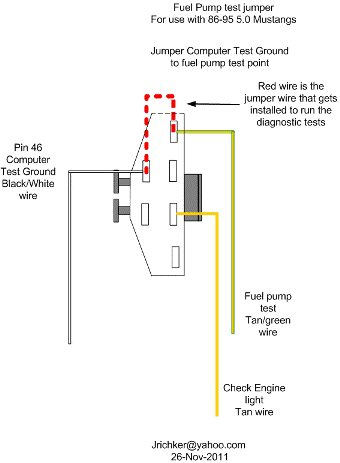
Look for power at the fuel pump - the fuel pump has a connector at the rear of the car with a pink/black wire and a black wire that goes to the fuel pump. The pink/black wire should be hot when the test connector is jumpered to the test position. . To trick the fuel pump into running, find the ECC test connector and jump the connector in the lower RH corner to ground.
86-90 Models:
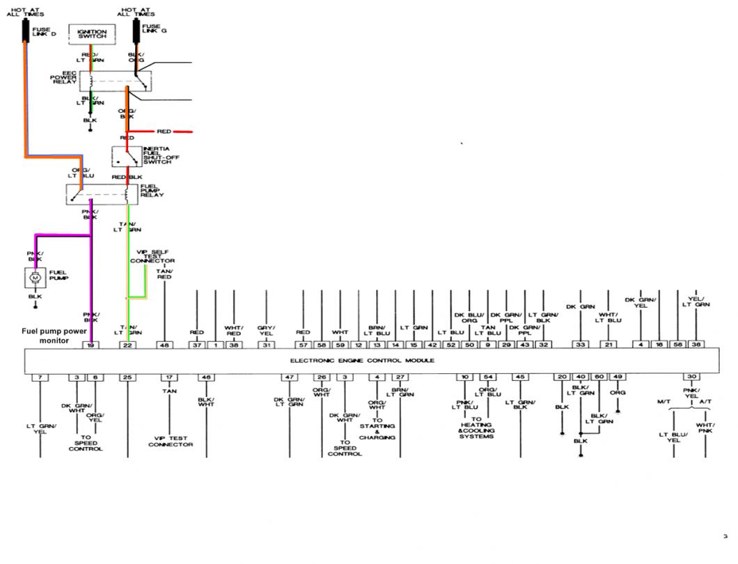
Using the diagram, check the red/black wire from the fuel pump relay: you should see 12 volts or so. If not, check the inertia switch: on a hatch it is on the drivers side by the taillight. Look for a black rubber plug that pops out: if you don't find it, then loosen up the plastic trim. Check for voltage on both sides of the switch. If there is voltage on both sides, then check the Pink/black wire on the fuel pump relay: it is the power feed to the fuel pump. Good voltage there, then the fuel pump body to tank wiring harness connector is the likely culprit since it is getting power. No voltage there, check the Orange/Lt blue wire, it is the power feed to the fuel pump relay & has a fuse link in it. Good voltage there & at the Pink/black wire, swap the relay.
Keep in mind that the relay wiring and socket can also cause intermittent problems. Clean the relay socket with non-flammable brake parts cleaner or electrical contact cleaner. If you find damaged wiring at the relay socket, replacement pigtail socket assemblies are available at the auto parts stores. Be sure to solder the wires and cover the solder joints with heat shrink tubing if you replace the relay socket.
How to clear codes.
Clearing the codes by pressing a button on the scan tool or disconnecting the test jumper used to start the code dump does not erase the “learned settings”. All it does is erase the stored codes in memory.
You must clear the codes anytime you replace any sensor. The following tells you how and is different from the method above
Clear the computer codes by disconnecting the battery negative terminal and turn the headlights on. Turn the headlights off and reconnect the all sensors including the MAF and anything else you may have disconnected. Then reconnect the battery negative cable.. This clears all spurious codes may have been generated while troubleshooting problems. It also clears the adaptive settings that the computer "learns" as it operates. Clearing the codes does not fix the code problems, it just gives you a clean slate to start recording what the computer sees happening.
Run the car for at least 30 minutes of driving and dump the codes again to assure that you have fixed the code problem or sensor problem. This is necessary for the computer to relearn the adaptive settings that the computer uses for proper operation. The engine may run rough at first, but should smooth out as it runs for the 15-20 minute learning period.
Code 66 or 157 MAF below minimum test voltage.
Revised 15 mar 2018 to clarify how to do resistance checks on the MAF wiring
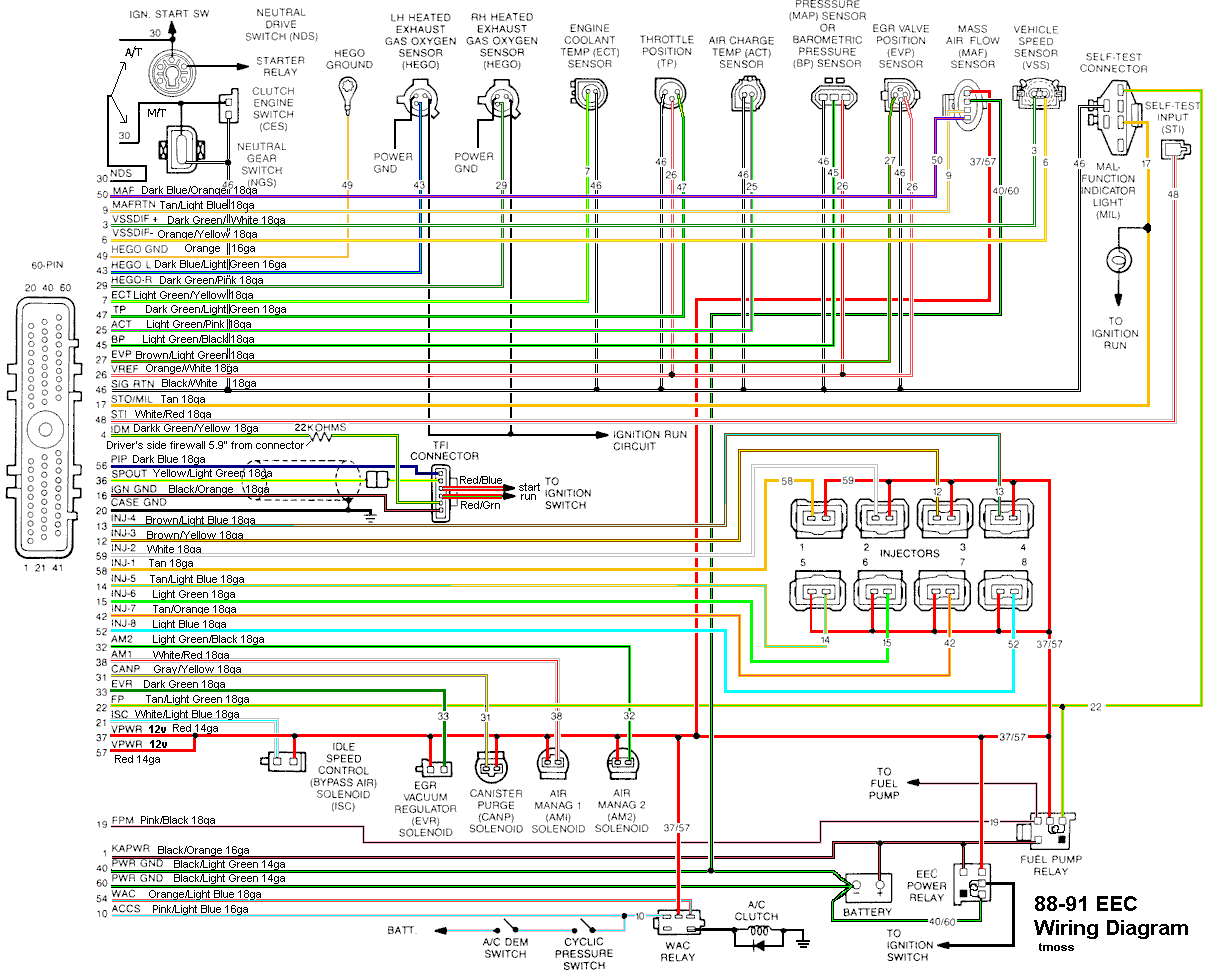
Insufficient or no voltage from MAF. Dirty MAF element, bad MAF, bad MAF wiring, missing power to MAF. Check for missing +12 volts on this circuit. Check the two links for a wiring diagram to help you find the red wire for computer power relay switched +12 volts. Check for 12 volts between the red and black wires on the MAF heater (usually pins A & B). while the connector is plugged into the MAF. This may require the use of a couple of safety pins to probe the MAF connector from the back side of it.
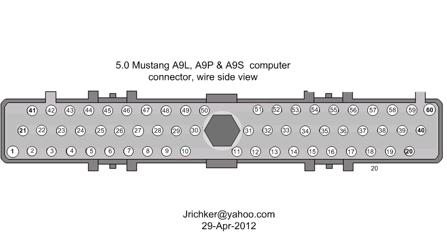
Computer wiring harness connector, wire side
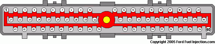
Computer wiring harness connector, computer side side
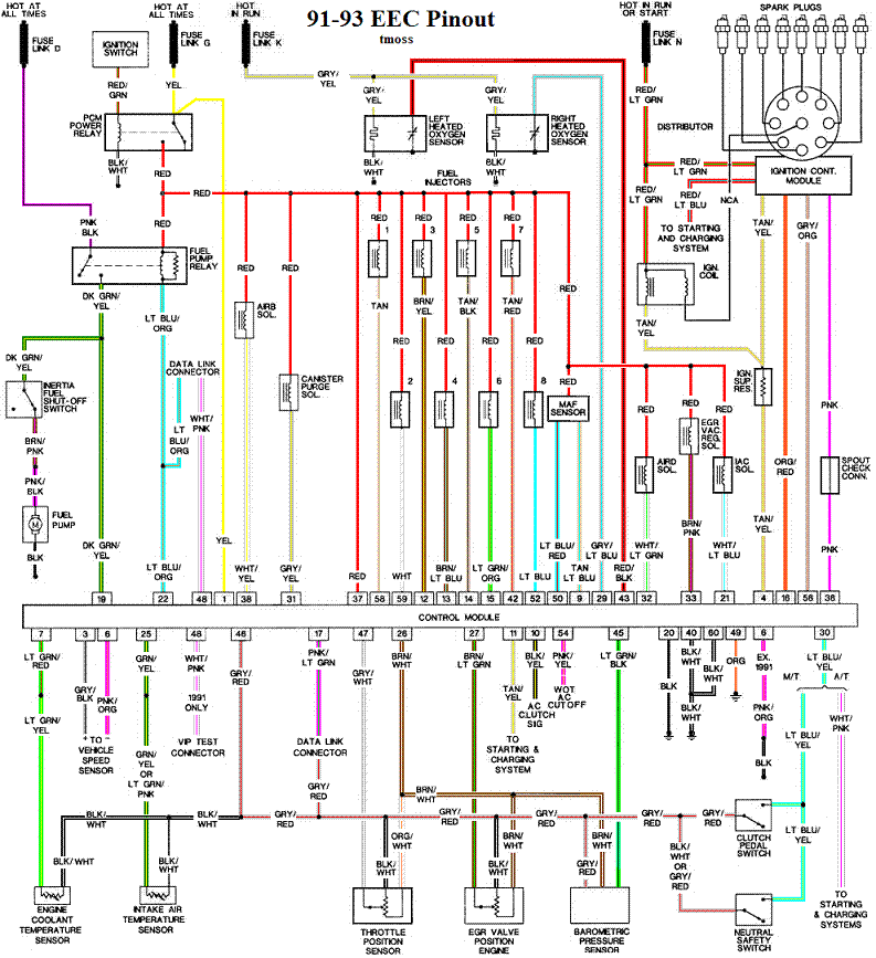
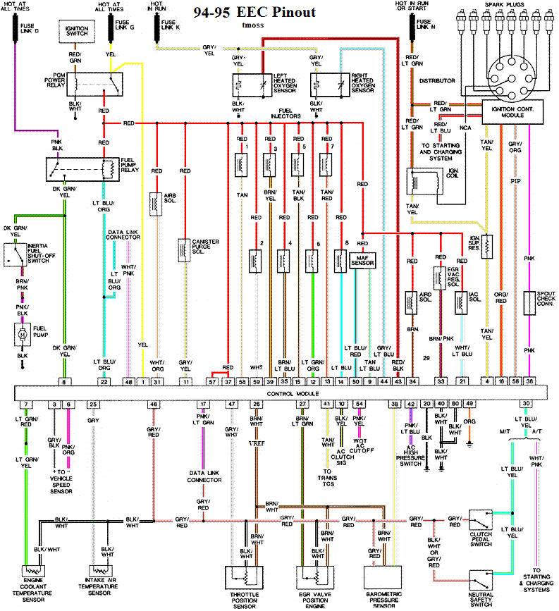
Diagrams courtesy of Tmoss and Stang&2Birds
ECC Diagram for 88-90 5.0 Mustangs
ECC Diagram for 91-93 5.0 Mustangs
94-95 Diagram for 94-95 5.0 Mustangs[/b]
How the MAF works
There are three parts in a MAF: the heater, the sensor element and the amplifier. The heater heats the MAF sensor element causing the resistance to increase. The amplifier buffers the MAF output signal and has a resistor that is laser trimmed to provide an output range compatible with the computer's load tables. Changes in RPM causes the airflow to increase or decrease, changing the voltage output.. The increase of air across the MAF sensor element causes it to cool, allowing more voltage to pass and telling the computer to increase the fuel flow. A decrease in airflow causes the MAF sensor element to get warmer, decreasing the voltage and reducing the fuel flow.
The MAF element is secured by 2 screws & has 1 wiring connector. To clean the element, remove it from the MAF housing and spray it down with electronic parts cleaner or non-inflammable brake parts cleaner (same stuff in a bigger can and cheaper too).
89-90 Model cars: Measure the MAF output at pins C & D on the MAF connector (dark blue/orange and tan/light blue) or at pins 50 & 9 on the computer. Be sure to measure the sensor output by measuring across the pins and not between the pins and ground.
91-95 Model cars: Measure the MAF output at pins C & D on the MAF connector light blue/red and tan/light blue) or at pins 50 & 9 on the computer. Be sure to measure the sensor output by measuring across the pins and not between the pins and ground.
At idle = approximately .6 volt
20 MPH = approximately 1.10 volt
40 MPH = approximately 1.70 volt
60 MPH = approximately 2.10 volt
Actually MAF pins C & D float with reference to ground. The signal output of the MAF is a differential amplifier setup. Pins C & D both carry the output signal, but one pin's output is inverted from the other. The difference in signal between C & D is what the computer's input circuit is looking for. The difference in the two outputs helps cancel out electrical noise generated by the ignition system and other components. Since the noise will be of the same polarity, wave shape and magnitude, the differential input of the computer electronically subtracts it from the signal. Then it passes the signal on to an Analog to Digital converter section inside the computer's CPU chip.
Check the resistance of the MAF signal wiring
For the next 2 checks make your measurement with the MAF disconnected from the wiring harness.
Pin D on the MAF wiring harness and pin 50 on the computer (dark blue/orange wire) should be less than 2 ohms. Pin C on the MAF wiring harness and pin 9 on the computer (tan/light blue wire) should be less than 2 ohms.
There should be a minimum of 10K ohms between either pin C or D on the MAF wiring connector and pins A or B.
Reconnect the MAF to the wiring harness and proceed to the next section.
See the following website for some help from Tmoss (diagram designer) & Stang&2Birds (website host) for help on 88-95 wiring http://www.veryuseful.com/mustang/tech/engine/
Ignition switch wiring
http://www.veryuseful.com/mustang/tech/engine/images/IgnitionSwitchWiring.gif
Fuel pump, alternator, ignition & A/C wiring
http://www.veryuseful.com/mustang/tech/engine/images/fuel-alt-links-ign-ac.gif
Computer,. actuator & sensor wiring
http://www.veryuseful.com/mustang/tech/engine/images/88-91_5.0_EEC_Wiring_Diagram.gif
Fuse panel layout
http://www.veryuseful.com/mustang/tech/engine/images/MustangFuseBox.gif
Vacuum routing
http://www.veryuseful.com/mustang/tech/engine/images/mustangFoxFordVacuumDiagram.jpg
Look for a failing fuel pump relay, bad connections or broken wiring. The fuel pump relay is located under the passenger seat. On Mass Air Conversions, the signal lead that tells the computer that the fuel pump has power may not have been wired correctly.
See http://www.stangnet.com/tech/maf/massairconversion.html
Look for power at the fuel pump - the fuel pump has a connector at the rear of the car with a pink/black wire and a black wire that goes to the fuel pump. The pink/black wire should be hot when the test connector is jumpered to the test position. . To trick the fuel pump into running, find the ECC test connector and jump the connector in the lower RH corner to ground.
86-90 Models:
Using the diagram, check the red/black wire from the fuel pump relay: you should see 12 volts or so. If not, check the inertia switch: on a hatch it is on the drivers side by the taillight. Look for a black rubber plug that pops out: if you don't find it, then loosen up the plastic trim. Check for voltage on both sides of the switch. If there is voltage on both sides, then check the Pink/black wire on the fuel pump relay: it is the power feed to the fuel pump. Good voltage there, then the fuel pump body to tank wiring harness connector is the likely culprit since it is getting power. No voltage there, check the Orange/Lt blue wire, it is the power feed to the fuel pump relay & has a fuse link in it. Good voltage there & at the Pink/black wire, swap the relay.
Keep in mind that the relay wiring and socket can also cause intermittent problems. Clean the relay socket with non-flammable brake parts cleaner or electrical contact cleaner. If you find damaged wiring at the relay socket, replacement pigtail socket assemblies are available at the auto parts stores. Be sure to solder the wires and cover the solder joints with heat shrink tubing if you replace the relay socket.
How to clear codes.
Clearing the codes by pressing a button on the scan tool or disconnecting the test jumper used to start the code dump does not erase the “learned settings”. All it does is erase the stored codes in memory.
You must clear the codes anytime you replace any sensor. The following tells you how and is different from the method above
Clear the computer codes by disconnecting the battery negative terminal and turn the headlights on. Turn the headlights off and reconnect the all sensors including the MAF and anything else you may have disconnected. Then reconnect the battery negative cable.. This clears all spurious codes may have been generated while troubleshooting problems. It also clears the adaptive settings that the computer "learns" as it operates. Clearing the codes does not fix the code problems, it just gives you a clean slate to start recording what the computer sees happening.
Run the car for at least 30 minutes of driving and dump the codes again to assure that you have fixed the code problem or sensor problem. This is necessary for the computer to relearn the adaptive settings that the computer uses for proper operation. The engine may run rough at first, but should smooth out as it runs for the 15-20 minute learning period.
Code 66 or 157 MAF below minimum test voltage.
Revised 15 mar 2018 to clarify how to do resistance checks on the MAF wiring
Insufficient or no voltage from MAF. Dirty MAF element, bad MAF, bad MAF wiring, missing power to MAF. Check for missing +12 volts on this circuit. Check the two links for a wiring diagram to help you find the red wire for computer power relay switched +12 volts. Check for 12 volts between the red and black wires on the MAF heater (usually pins A & B). while the connector is plugged into the MAF. This may require the use of a couple of safety pins to probe the MAF connector from the back side of it.
Computer wiring harness connector, wire side
Computer wiring harness connector, computer side side
Diagrams courtesy of Tmoss and Stang&2Birds
ECC Diagram for 88-90 5.0 Mustangs
ECC Diagram for 91-93 5.0 Mustangs
94-95 Diagram for 94-95 5.0 Mustangs[/b]
How the MAF works
There are three parts in a MAF: the heater, the sensor element and the amplifier. The heater heats the MAF sensor element causing the resistance to increase. The amplifier buffers the MAF output signal and has a resistor that is laser trimmed to provide an output range compatible with the computer's load tables. Changes in RPM causes the airflow to increase or decrease, changing the voltage output.. The increase of air across the MAF sensor element causes it to cool, allowing more voltage to pass and telling the computer to increase the fuel flow. A decrease in airflow causes the MAF sensor element to get warmer, decreasing the voltage and reducing the fuel flow.
The MAF element is secured by 2 screws & has 1 wiring connector. To clean the element, remove it from the MAF housing and spray it down with electronic parts cleaner or non-inflammable brake parts cleaner (same stuff in a bigger can and cheaper too).
89-90 Model cars: Measure the MAF output at pins C & D on the MAF connector (dark blue/orange and tan/light blue) or at pins 50 & 9 on the computer. Be sure to measure the sensor output by measuring across the pins and not between the pins and ground.
91-95 Model cars: Measure the MAF output at pins C & D on the MAF connector light blue/red and tan/light blue) or at pins 50 & 9 on the computer. Be sure to measure the sensor output by measuring across the pins and not between the pins and ground.
At idle = approximately .6 volt
20 MPH = approximately 1.10 volt
40 MPH = approximately 1.70 volt
60 MPH = approximately 2.10 volt
Actually MAF pins C & D float with reference to ground. The signal output of the MAF is a differential amplifier setup. Pins C & D both carry the output signal, but one pin's output is inverted from the other. The difference in signal between C & D is what the computer's input circuit is looking for. The difference in the two outputs helps cancel out electrical noise generated by the ignition system and other components. Since the noise will be of the same polarity, wave shape and magnitude, the differential input of the computer electronically subtracts it from the signal. Then it passes the signal on to an Analog to Digital converter section inside the computer's CPU chip.
Check the resistance of the MAF signal wiring
For the next 2 checks make your measurement with the MAF disconnected from the wiring harness.
Pin D on the MAF wiring harness and pin 50 on the computer (dark blue/orange wire) should be less than 2 ohms. Pin C on the MAF wiring harness and pin 9 on the computer (tan/light blue wire) should be less than 2 ohms.
There should be a minimum of 10K ohms between either pin C or D on the MAF wiring connector and pins A or B.
Reconnect the MAF to the wiring harness and proceed to the next section.
See the following website for some help from Tmoss (diagram designer) & Stang&2Birds (website host) for help on 88-95 wiring http://www.veryuseful.com/mustang/tech/engine/
Ignition switch wiring
http://www.veryuseful.com/mustang/tech/engine/images/IgnitionSwitchWiring.gif
Fuel pump, alternator, ignition & A/C wiring
http://www.veryuseful.com/mustang/tech/engine/images/fuel-alt-links-ign-ac.gif
Computer,. actuator & sensor wiring
http://www.veryuseful.com/mustang/tech/engine/images/88-91_5.0_EEC_Wiring_Diagram.gif
Fuse panel layout
http://www.veryuseful.com/mustang/tech/engine/images/MustangFuseBox.gif
Vacuum routing
http://www.veryuseful.com/mustang/tech/engine/images/mustangFoxFordVacuumDiagram.jpg
Attachments
I can’t test any resistance through the pins because my car won’t stay on long enough. I disconnect the harness and it idles beautiful for about 20 seconds or so then dies. I tried resetting the codes but I can’t get the car running long enough to make a difference
You NEVER check resistance in a wire that has power applied to it. Doing so will give and erroneous reading and may damage the meter.I can’t test any resistance through the pins because my car won’t stay on long enough. I disconnect the harness and it idles beautiful for about 20 seconds or so then dies. I tried resetting the codes but I can’t get the car running long enough to make a difference
All resistance checks are done with the engine off and the power off.
Automotive circuits are mostly simple stuff: a power source, a connection path, a control device, a load, and a ground.
The battery/alternator is the positive power source.
The wire and fuses are the connection path.
Control devices are switches, relays and sensors.
A load is a light, motor, solenoid, relay coil or heater element.
In automotive circuits, grounds are the return path so the electrical power can flow from the load to the negative side of the power source.
Electricity flows like water:
Voltage is like pressure,
Current in amps is like volume,
Resistance is like the kink you put in a garden hose to decrease the pressure or volume.
Power is pressure multiplied by volume or voltage multiplied by current (amps)
Digest that, and you just got the first 3 days of Electricity 101.
Use some jumper wires (connection path and ground) to hook up a switch (control device), a battery (power source), a light bulb (load). Now make the light turn on and off with the switch.
That's the electrical lab for the first week of Electricity 101.
For free automotive electrical training, see Automotive Training and Resource Site . Once you are there, select online instruction. I have personally reviewed the material and it is very good. If you are new to automotive electrical troubleshooting, I highly recommend you spend a hour or so going through the material. You'll save at least that much time troubleshooting problems.
Using a Multimeter or DVM
Be careful, most cheap multimeters aren't capable of handling more that 10 amps. When you test current, the wires connected to the meter need to be the same size or larger than the wire that connects device under test to the power source.
Current (amps) is measured with the meter inline (series) with the device under test.
Most of the high current figures for radiator fans are the surge current figures. Any motor will draw -2-4 times the running current for about 1-2 seconds when it first starts spinning. That's why you use a slow blow fuse or a circuit breaker on a circuit that protects the wiring to a motor. Loads that have a lot of drag will draw higher current for a longer time when they first start up.
In automotive circuits, Voltage is measured from ground to power input of the device when it is turned on and operating.
Almost every meter has a different method for showing an open circuit. An open circuit is one with a break in it somewhere. That break can be a switch turned off, a fuse blown, a lamp burned out, a bad connector, a damaged circuit board or a cut or burned wire.
Without reading the instruction manual that came with your meter, I would not try to guess what your readings mean.
Step 1.) Find the instruction book that came with your Multimeter or DVM. Read it and familiarize yourself with how it works and how use it. If you lost the book or didn’t get one with it, do a Google search on the web to find the manufacturer’s web site & download a copy of the manual. Remember that while some meters auto-range to find the correct voltage range, the Ohms function ranges are usually set by the selector switch. Most of the resistance testing done in automotive troubleshooting uses the lowest Ohms range possible.
Step 2. ) Make sure that you know what test lead plugs into which jacks on the Multimeter or DVM. There are usually several different jacks on most Multimeter or DVMs, and they have different functions. Make sure that your battery(s) in the Multimeter are good: if you have any doubts, replace the battery(s).
Step 3.) Once you are sure that the Multimeter or DVM is functional and you have the leads plugged into the jacks for Ohms ( the Ω symbol), do some simple measurements to make sure that you know how to use it correctly. Set the switch to the lowest range and touch the leads together: you should not see “nothing” but you should see 0.3-1.0 ohms. Measure a 60 watt light bulb: cold it will measure about 17.5 Ohms. It you measure it while it is hot, the reading will be greater.
Step 4.) Make several test measurements using the ohms function and the DC volts function. Remember all resistance measurements must be done with the power off the circuit. This avoids false readings and possible damage to the ohmmeter.. Repeat steps 3 & 4 until you are sure that you can do it without making any mistakes.
Step 5.) Then see | Repair Guides | Understanding And Troubleshooting Electrical Systems | Basic Electrical Theory | AutoZone.com and carefully study ALL the information under the Heading Chassis Electrical, Basic Electricity – Understanding & Troubleshooting
Step 6.) Apply what you have learned and make the test measurements using the information in the wiring diagrams & my previous posts.
Don't be in too much of a hurry to bolt all the new, pretty, shiny parts together. Take the simple steps now and you will save yourself lots of time and trouble later.
I can’t read voltage through pins without it staying on long enough is what I should have said. I am an hvac tech by trade and am very familiar with electrical. Sounded stupid. But I can’t test voltage to pins because the car won’t run. I have my 12 volts
Fix the 96 code first. The fuel pump isn't delivering enough fuel to keep the engine running.I can’t read voltage through pins without it staying on long enough is what I should have said. I am an hvac tech by trade and am very familiar with electrical. Sounded stupid. But I can’t test voltage to pins because the car won’t run. I have my 12 volts
Check fuel pressure:
The local auto parts store may rent or loan a fuel pressure test gauge if you don't have one.
Disconnect the vacuum line from the fuel pressure regulator. Check it for evidence of fuel present in the line by removing it and blowing air through it. If you find fuel, the fuel pressure regulator has failed. Reinstall the line; leave the fuel pressure regulator end of the vacuum line disconnected. Then cap or plug the open end of the vacuum line and stow it out of the way.
Connect the fuel pressure test gauge to the Schrader port located just behind the alternator.
Turn the ignition switch on & start the engine. Observe the pressure: you should see 38-41 PSI at idle.
Turn the ignition off; reconnect the vacuum line to the fuel pressure regulator. Then disconnect the fuel pressure test gauge. Watch out for squirting gas when you do this.
Fuel pump pressure test
Disconnect the larger of the two fuel lines up by the Schrader valve. It is the return line and does not have the Schrader valve on it. Find a piece of rubber fuel hose and clamp it on the return line coming from the regulator. Stick a bolt in the other end of the hose and make sure that all your connections are tight and leak proof as possible. When this powers up, you don't want fuel squirting everywhere. Hook up the fuel pressure test gauge. Turn the ignition switch on and watch for leaks. You may want to use a helper inside the car to cut the switch off quickly if you have a leak. To trick the fuel pump into running, find the EEC test connector and jump the connector in the Upper RH corner to ground.
Caution!!! You have blocked the return line for the fuel pump! Pressure will rise very quickly past safe levels with a good pump
If the pressure goes up past 55 PSI, the pump is good and the fuel pressure regulator is bad. If the fuel pressure does not hit 55 PSI or more in a few seconds, the pump is bad or you have electrical problems.
Found that I have under 10 psi of fuel pressure. I hear the pump prime but it’s like a second long. Could that be fuel filter? Either way going to change it and begin testing voltage through the circuit tomorrow. I’ve replaced the fuel pump relay but it didn’t change

the fuel pump will prime when the key is turned to the koeo position, the pump will then be triggered to run when the ecu gets an RPM input from the PIP in the distributor... the test connector jumper should cause the pump to run the entire time the jumper is applied, a low pressure issue could be caused from...
1.-- bad fuel pressure regulator - this is on the fuel rail
2. a bad or damaged fuel pump, this includes the line that connects the pump to the fuel pickup inside the tank, sometimes the line comes loose or ruptures.
3. a heavily clogged fuel filter may cause a low pressure issue with the car running but this usually shows up above idle speed..
1.-- bad fuel pressure regulator - this is on the fuel rail
2. a bad or damaged fuel pump, this includes the line that connects the pump to the fuel pickup inside the tank, sometimes the line comes loose or ruptures.
3. a heavily clogged fuel filter may cause a low pressure issue with the car running but this usually shows up above idle speed..

Blown88GT
Founding Member
An HVAC tech would know this would do nothing to fix it.Found that I have under 10 psi of fuel pressure. I hear the pump prime but it’s like a second long. Could that be fuel filter? Either way going to change it and begin testing voltage through the circuit tomorrow. I’ve replaced the fuel pump relay but it didn’t change.
That's like saying the pressure is low in the A/C compressor, so replace the contactor & the capacitor.
I know this was never a part of your training, i.e. just start throwing parts at it until you find something that works.
I think Steve can find a spot in his Journeyman training class for you.
No where close buddy. No pressure AFTER a filter that can clog. Nothing at all like changing an electrical part. Cars been sitting for 4 years. I thought this thread was to get some help, not for a joke founding member to post ridiculous comments like that. Appreciate the help buddy
Oh an one more thing blown88, you of all people should know changing a fuel filter is a maintenance thing which is part of what I’m doing. Clown
Let me start by saying that he is correct... if the relay was bad the pump would not run at all, the above schematic shows that... that is what he was eluding too.. you will have to forgive his forwardness, he is an old retired electrical engineer.. and knows his  .
.
you are correct on the filter but it would have to be mucho clogged, old fuel can vanish and clog the filter quickly its worth replacing anyway.
we are here to help, but I would appreciate it if we could all calm down a bit.
.you are correct on the filter but it would have to be mucho clogged, old fuel can vanish and clog the filter quickly its worth replacing anyway.
we are here to help, but I would appreciate it if we could all calm down a bit.

Let me jump in here.
we get a plethora of new members that come in here looking for help and when given advice on a fix they say, like you did, I will do this or do that when they were given a procedure to find and fix the problem without wasting time and money.
that 'clown' has some credibility:
1988 GT, 57k miles, Original Owner
ProCharger P600B, FRPP Headers, Flowmaster F2, 3G Alt, Mk8 Fan & DCC, 3.55's, Prog Springs, ST Brace, G/Trac Bar, Subfrms, UCA, LCA, FCA, Tokico 5-ways, C/C Plates, CSA 16x8, Bridgestone RE760 225/50R16, Megasquirt DIYPNPF60, LC2 wideband, C&L76mm MAF w/47's
do you think he can build and maintain the above ride and not know what makes it work?
take a breath, then dive into changing that fuel pump, fuel filter and check your fuel pump regulator.
we get a plethora of new members that come in here looking for help and when given advice on a fix they say, like you did, I will do this or do that when they were given a procedure to find and fix the problem without wasting time and money.
that 'clown' has some credibility:
1988 GT, 57k miles, Original Owner
ProCharger P600B, FRPP Headers, Flowmaster F2, 3G Alt, Mk8 Fan & DCC, 3.55's, Prog Springs, ST Brace, G/Trac Bar, Subfrms, UCA, LCA, FCA, Tokico 5-ways, C/C Plates, CSA 16x8, Bridgestone RE760 225/50R16, Megasquirt DIYPNPF60, LC2 wideband, C&L76mm MAF w/47's
do you think he can build and maintain the above ride and not know what makes it work?
take a breath, then dive into changing that fuel pump, fuel filter and check your fuel pump regulator.
I didn’t say he had no credibility. All I was saying is I was gonna change the fuel filter anyways. I came here for help, not to be criticized by an engineer on my hvac/electrical knowledge.
Blown88GT
Founding Member
You are the one that offered up your experience to prove you know what you're doing.
Let the pump prime a couple times, it won't read full pressure in the 2-3 seconds of ignition on/engine off.
You can run the pump continuously with the ignition on by adding a temporary jumper wire, see Post #6 above.
Let the pump prime a couple times, it won't read full pressure in the 2-3 seconds of ignition on/engine off.
You can run the pump continuously with the ignition on by adding a temporary jumper wire, see Post #6 above.
Blown88GT
Founding Member
Thanks for the props, but one of my jobs was just a bit more complicated than any car.Let me jump in here.
we get a plethora of new members that come in here looking for help and when given advice on a fix they say, like you did, I will do this or do that when they were given a procedure to find and fix the problem without wasting time and money.
that 'clown' has some credibility:
1988 GT, 57k miles, Original Owner
ProCharger P600B, FRPP Headers, Flowmaster F2, 3G Alt, Mk8 Fan & DCC, 3.55's, Prog Springs, ST Brace, G/Trac Bar, Subfrms, UCA, LCA, FCA, Tokico 5-ways, C/C Plates, CSA 16x8, Bridgestone RE760 225/50R16, Megasquirt DIYPNPF60, LC2 wideband, C&L76mm MAF w/47's
do you think he can build and maintain the above ride and not know what makes it work?
take a breath, then dive into changing that fuel pump, fuel filter and check your fuel pump regulator.
The one at the bottom for NASA. They only made 1 test aircraft.
This one, too. Designed & build most of the hardware.
Mid-Infrared Advanced Chemical Laser (MIRACL)
Last edited:
Fuel Pump Troubleshooting for 87-90 MustangsFound that I have under 10 psi of fuel pressure. I hear the pump prime but it’s like a second long. Could that be fuel filter? Either way going to change it and begin testing voltage through the circuit tomorrow. I’ve replaced the fuel pump relay but it didn’t change
Revised 1-Dec-2015 to add fuse links diagram.
Clue – listen for the fuel pump to prime when you first turn the ignition switch on. It should run for 1-3 seconds and shut off. To trick the fuel pump into running, find the ECC test connector and jump the connector in the upper LH corner to ground.
Foxbody Diagnostic connector
Foxbody Diagnostic connector close up view
Turn the ignition switch on when you do this test.
If the fuse links are OK, you will have power to the pump. Check fuel pressure – remove the cap from the Schrader valve behind the alternator and depress the core. Fuel should squirt out, catch it in a rag. A tire pressure gauge can also be used if you have one - look for 37-40 PSI. Beware of fire hazard when you do this.
No fuel pressure, possible failed items in order of their probability:
A.) Tripped inertia switch – press reset button on the inertia switch. The hatch cars hide it under the plastic trim covering the driver's side taillight. Use the voltmeter or test light to make sure you have power to both sides of the switch
B.) Fuel pump power relay – located under the driver’s seat in most Mustangs built before 92. See the diagram to help identify the fuel pump relay wiring colors. Be sure to closely check the condition of the relay, wiring & socket for corrosion and damage.
C.) Clogged fuel filter
D.) Failed fuel pump
E.) Blown fuse link in wiring harness.
F.) Fuel pressure regulator failed. Remove vacuum line from regulator and inspect for fuel escaping while pump is running.
The electrical circuit for the fuel pump has two paths, a control path and a power path.
Control Path
The control path consists of the inertia switch, the computer, and the fuel pump relay coil. It turns the fuel pump relay on or off under computer control. The switched power (red wire) from the ECC relay goes to the inertia switch (red/black wire) then from the inertia switch to the relay coil and then from the relay coil to the computer (tan/ Lt green wire). The computer provides the ground path to complete the circuit. This ground causes the relay coil to energize and close the contacts for the power path. Keep in mind that you can have voltage to all the right places, but the computer must provide a ground. If there is no ground, the relay will not close the power contacts.
Power Path
The power path picks up from a fuse link near the starter relay. Fuse links are like fuses, except they are pieces of wire and are made right into the wiring harness. The feed wire from the fuse link (orange/ light blue wire) goes to the fuel pump relay contacts. The fuse links are in a bundle up near the starter relay; you will have to unwrap the wiring harness to find them.
Fuse links
Fuse links come with a current rating just like fuses. A clue as to what current they are designed for is to look at the size wire they protect. Fuse link material is available at most good auto parts stores. There may even be a fuse link already made up specifically for your car. Just be sure to solder the connection and cover it with heat shrink tubing.
Heat shrink tubing is available at Radio Shack or other electronics supply stores.
See the video below for help on soldering and heat shrinking wiring. There is a lot of useful help and hints if you don’t do automotive electrical work all the time.
View: http://youtu.be/uaYdCRjDr4A
When the contacts close because the relay energizes, the power flows through the contacts to the fuel pump (light pink/black wire). Notice that pin 19 on the computer is the monitor to make sure the pump has power. The fuel pump has a black wire that supplies the ground to complete the circuit.
Remember that the computer does not source any power to actuators, relays or injectors, but provides the ground necessary to complete the circuit. That means one side of the circuit will always be hot, and the other side will go to ground or below 1 volt as the computer switches on that circuit.
Now that you have the theory of how it works, it’s time to go digging.
All voltage reading are made with one voltmeter lead connected to the metal car body unless otherwise specified
Check for 12 volts at the red wire on the inertia switch. No 12 volts at the inertia switch, the ignition switch is turned off or faulty or there is no power to the EEC (computer) power relay. To be sure look for good 12 volts on the red wire on any fuel injector.
Good 12 volts means the EEC relay is working. No 12 volts and the ECC wiring is at fault.
Look for 12 volts on the red/green wire on the ignition coil: no 12 volts and the ignition switch is faulty, or the fuse link in the ignition power wire has blown. No 12 volts here and the ECC relay won’t close and provide power to the inertia switch. Check the Red/black wire on the inertia switch, it should have 12 volts. No 12 volts there, either the inertia switch is open or has no power to it. Check both sides of the inertia switch: there should be power on the Red wire and Red/Black wire. Power on the Red wire and not on the Red/Black wire means the inertia switch is open. Push the button on the side of it to reset it, and then recheck. Good 12 volts on one side and not on the other means the inertia switch has failed.
Look for 12 volts at the Orange/Lt. Blue wire (power source for fuel pump relay). No voltage or low voltage, bad fuse link, bad wiring, bad ignition switch or ignition switch wiring or connections. There is a mystery connector somewhere under the driver’s side kick panel, between the fuel pump relay and the fuse link.
Turn on the key and jumper the fuel pump test connector to ground as previously described. Look for 12 volts at the Light Pink/Black wire (relay controlled power for the fuel pump). No voltage there means that the relay has failed, or there is a broken wire in the relay control circuit.
Pump wiring: Anytime the ignition switch is in the Run position and the test point is jumpered to ground, there should be at least 12 volts present on the black/pink wire. With power off, check the pump ground: you should see less than 1 ohm between the black wire and chassis ground.
The yellow wire is the fuel tank sender to the fuel quantity gage. The two black wires are grounds. One ground is for the fuel tank sender and the other is the fuel pump. The ground for the fuel pump may be larger gauge wire that the fuel tank sender ground wire.
Make sure that the power is off the circuit before making any resistance checks. If the circuit is powered up, your resistance measurements will be inaccurate.
You should see less than 1 Ohm between the black wire(s) and ground. To get some idea of what a good reading is, short the two meter leads together and observe the reading. It should only be slightly higher when you measure the black wire to ground resistance.
The Tan/Lt Green wire provides a ground path for the relay power. With the test connector jumpered to ground, there should be less than .75 volts. Use a test lamp with one side connected to battery power and the other side to the Tan/Lt Green wire. The test light should glow brightly. No glow and you have a broken wire or bad connection between the test connector and the relay. To test the wiring from the computer, remove the passenger side kick panel and disconnect the computer connector. It has a 10 MM bolt that holds it in place. With the test lamp connected to power, jumper pin 22 to ground and the test lamp should glow. No glow and the wiring between the computer and the fuel pump relay is bad.
Computer: If you got this far and everything else checked out good, the computer is suspect. Remove the test jumper from the ECC test connector located under the hood. Probe computer pin 22 with a safety pin and ground it to chassis. Make sure the computer and everything else is connected. Turn the ignition switch to the Run position and observe the fuel pressure. The pump should run at full pressure.
If it doesn't, the wiring between pin 22 on the computer and the fuel pump relay is bad.
If it does run at full pressure, the computer may have failed.
Keep in mind that the computer only runs the fuel pump for about 2-3 seconds when you turn the key to the Run position. This can sometimes fool you into thinking the computer has died. Connect one lead of the test light to power and the other lead to computer pin 22 with a safety pin. With the ignition switch Off, jumper the computer into self test mode like you are going to dump the codes. Turn the ignition switch to the Run position. The light will flicker when the computer does the self test routine. A flickering light is a good computer. No flickering light is a bad computer.
Remove the test jumper from the ECC test connector located under the hood.
Fuel pump runs continuously: The fuel pump relay contacts are stuck together or the Tan/Lt Green wire has shorted to ground. In extreme ghetto cases, the pump relay may have been bypassed. Remove the fuel pump relay from its socket. Then disconnect the computer and use an ohmmeter to check out the resistance between the Tan/Lt Green wire and ground. You should see more than 10 K Ohms (10,000 ohms) or an infinite open circuit. Be sure that the test connector isn’t jumpered to ground.
If the wiring checks out good, then the computer is the likely culprit.
Prior to replacing the computer, check the computer power ground. The computer has its own dedicated power ground that comes off the ground pigtail on the battery ground wire. Due to it's proximity to the battery, it may become corroded by acid fumes from the battery. It is a black cylinder about 2 1/2" long by 1" diameter with a black/lt green wire. You'll find it up next to the starter solenoid where the wire goes into the wiring harness
If all of the checks have worked OK to this point, then the computer is bad. The computers are very reliable and not prone to failure unless there has been significant electrical trauma to the car. Things like lightning strikes and putting the battery in backwards or connecting jumper cables backwards are about the only thing that kills the computer.
See the following website for some help from Tmoss (diagram designer) &
Stang&2Birds (website host)
http://www.veryuseful.com/mustang/tech/engine/images/IgnitionSwitchWiring.gif
http://www.veryuseful.com/mustang/tech/engine/images/fuel-alt-links-ign-ac.gif
http://www.veryuseful.com/mustang/tech/engine/images/88-91eecPinout.gif
Well I respect your knowledge. I’m just here for help. I jumped the connector out and ran the fuel pump. Still only have under 10 psi. Where would my inertia switch be on a notchback?
Similar threads
- Replies
- 2
- Views
- 126

- Replies
- 4
- Views
- 193
- Replies
- 12
- Views
- 989

- Replies
- 8
- Views
- 379

- Replies
- 2
- Views
- 286