Battery relocation... Wiring discussion.

I just wanna pick the brains of some of the electrical Guru's on theses boards for a little bit. Once I fix my stance problem (car sits on its ass), The battery is going in the trunk. Im trying to make sure my wiring ideas will be good and not cause problems.

I have a 3g (130 amp) alt, with a 4ga wire connecting it to the starter solenoid which is tucked away in the diverside fender. The battery would go on the passenger side of the trunk (or should I put it on the driver side?). 1/0ga cable would go from the negative post on the batt to the Quad shock mount bolt. 4ga wire would then go from that same spot (Quad shock mount bolt) to the stock Batt ground (the cable would be hidden under the frame rail and radiator suport and under the lower radiator hose to make it look like a clean install.). Then I would run 4ga cable from this spot (stock Batt ground) to the CPU ground (which is hidden in the fender, again this cable would be hidden to make it look good). As you can see I understand this part, its the positive Im curious about:

I want to mount a turn off switch in the same fasion as Bottlefed92, behind the rear liscense plate. I would run 4ga cable from the Positive Batt termintal to the cut-off switch. Then I would run 4ga cable from the otherside of the cut-off switch to the starter solenoid. This would pos another problem however, if I installed a mini stater, the stud on the solenoid isn't long enough. So here are my questions ideas I have then:

1) Instead of running the 4ga (positive) cable from the cut-off to the starter solenoid, can I run that same cable from the cut-off switch to the post on the 3g Alt? that way I would only need to run the Alt cable to the start solenoid? or would this cause problems?

2) If I can do what is asked in number 1, how about this for the ground: Instead of running the ground from the quad shock to the stock ground to the CPU ground, can I run it from the quad shock to the CPU ground to the stock ground?

3) Does this setup make sense? Or would I just run into electrical and ground problems?
 
  • Sponsors (?)


Ok to help you out, heres some crude drawings I made to help you get teh picture: Which one is the right/good way to go, A or B.

746333_40_full.jpg
 
Rear mounted battery ground wiring. Follow this plan and you will have zero
ground problems.


One 1 gauge or 1/0 gauge wire from battery negative post to a clean shiny spot
on the chassis near the battery. Use a 5/16” bolt and bolt it down to make the
rear ground. Use a 1 gauge or 1/0 gauge wire from the rear ground bolt to a clean
shiny spot on the block.

One 4 gauge wire from the block where you connected the battery ground wire to
the chassis ground where the battery was mounted up front. Use a 5/16” bolt
and bolt down the 4 gauge engine to chassis ground, make sure that it the metal
around the bolt is clean & shiny. This is the alternator power ground.

The computer has a dedicated power ground wire with a cylindrical quick connect
(about 2 ½”long by 1” diameter. It comes out of the wiring harness near the
ignition coil & starter solenoid (or relay). Be sure to bolt it to the chassis ground
in the same place as you bolted the alternator power ground. This is an
absolute don’t overlook it item for EFI cars


Picture courtesy timewarped1972
ground.jpg

attachment.php

Crimp or even better, solder the lugs on the all the wire. The local auto stereo
shop will have them if the auto parts store doesn't. Use some heat shrink tubing
to cover the lugs and make things look nice.


For a battery cut off switch, see
http://www.moroso.com/catalog/categorydisplay.asp?catcode=42225 is the switch
http://www.moroso.com/catalog/images/74102_inst.pdf
Use the super duty switch and the following tech note to wire it and you
will be good to go.

Use the Moroso plan for the alternator wiring and you risk a fire.
The 10 gauge wire they recommend is even less adequate that
the stock Mustang wiring.

There is a solution, but it will require about 40' of 18 gauge green wire.

Wire the battery to the two 1/4" posts as shown in the diagram.

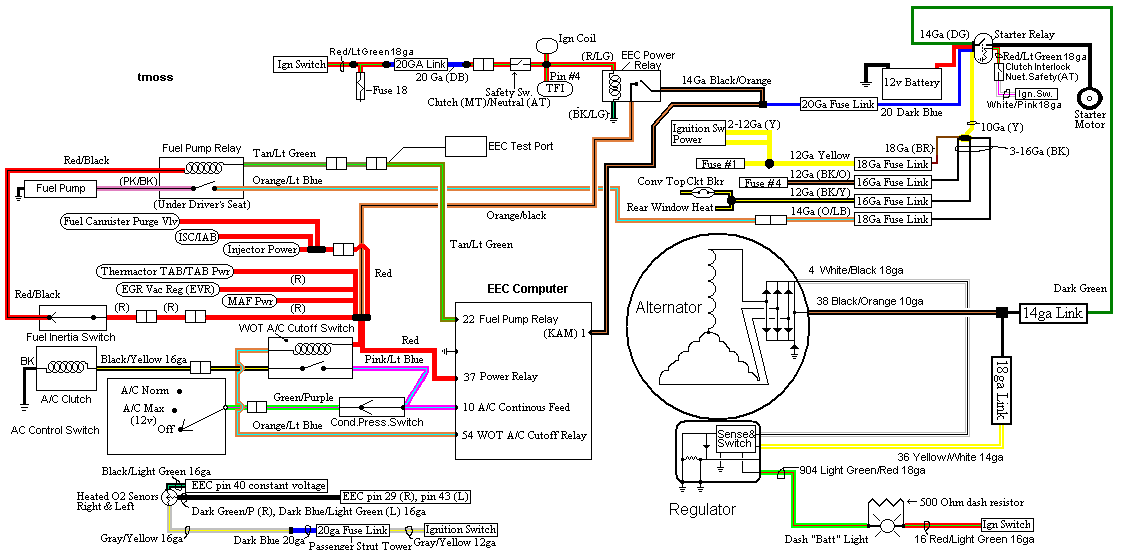
The alternator requires a different approach. On the small alternator plug
there is a green wire. On the diagram it is #904, lt green/red wire that connects
to the alternator and dash light. It is the sense lead that turns the regulator on
when the ignition switch is in the run position. Cut the green wire and solder the
40' of green wire between the two pieces. Use some heat shrink to cover the
splices. See http://fordfuelinjection.com/?p=7 for some excellent
help on soldering & using heat shrink tubing.

Run the green wire back to the Moroso switch and cut off the excess wire.
Try to run the green wire inside the car and protect it from getting cut or
chaffed. Crimp a 18 gauge ring terminal (red is 18 gauge color code for the crimp
on terminals) on each wire. Bolt one ring terminal to each of the 3/16" studs.
Do not add the jumper between the 1/4" stud and the 3/16" stud as shown it the
Moroso diagram.

How it works:
The green/red wire is the ignition on sense feed to the regulator. It supplies
power to the regulator when the ignition switch is in the run position. Turn
the Moroso switch to off, and the sense voltage goes away, the voltage
regulator shuts off and the alternator quits making power.

See the following website for some help from Tmoss (diagram designer) &
Stang&2Birds (website host) for help on 88-90 wiring and lots more…

http://www.veryuseful.com/mustang/tech/engine/images/IgnitionSwitchWiring.gif

http://www.veryuseful.com/mustang/tech/engine/images/fuel-alt-links-ign-ac.gif

http://www.veryuseful.com/mustang/tech/engine/images/88-91eecPinout.gif

Diagram courtesy of Tmoss and Stang&2birds.
fuel-alt-links-ign-ac.gif
 
As many times as the above has been posted and re-posted, the one thing I don't quite get is how shutting off power from the alternator will result in a shut-down condition ... unless, of course, the same switch also breaks the circuit for the battery, as well...? (Haven't gotten my hands on one yet, so I dunno how many posts it features on the back ... two large and two small, one pair for battery and one for alternator, right?)
 
Darkwriter77 said:
As many times as the above has been posted and re-posted, the one thing I don't quite get is how shutting off power from the alternator will result in a shut-down condition ... unless, of course, the same switch also breaks the circuit for the battery, as well...? (Haven't gotten my hands on one yet, so I dunno how many posts it features on the back ... two large and two small, one pair for battery and one for alternator, right?)
The moroso switch turns off the battery & alternator at the same time. Take away the field current and the alternator quits making power.
 
excuse me while i ressurect this thread. im ordering everyhting i need for the swap tonite, so let me go over what Jrichker said to make sure im clear. The ground i use 1 or 1/0 gauge to the frame, then the same cable to the block, then 4 gauge from the block to the EEC ground. For the positive i run the cable from the batt to the cutoff switch, then from the cutoff switch to the starter solenoid. Then the green 18guage wire i wire to the cutoff switch to the green wire leading to the alt.

Just some Final questions:
What gauge wire for the positive side should i use?
When i wire the green wire into the alternator, do i just splice it into the wire, to make a "Y" connection in a sense? or do i completely cut it and only use one side? thanks alot guys. Sorry for the repititions and questions but i want to be positive, thanks for your patience too.
 
The positive side uses a 1 or 1/0 gauge feed from the battery positive terminal to the starter solenoid.

The 904 Lt green/red wire gets cut into two pieces & the 40' green wire is spliced in. The other ends of the green wire connect to the two 10/32 studs on the screws on the Moroso switch. In effect, you are just putting the switch in between the two ends of the 904 Lt green/red wire, but you extend them to reach the switch in the rear of the car.
 
Is the switch necessary for street use? I know at the track it is manditory. Just wondering how many people have actually installed the switch when they relocate the battery. Anyone have any pics of where they put the switch?
 
jrichker said:
The positive side uses a 1 or 1/0 gauge feed from the battery positive terminal to the starter solenoid.

The 904 Lt green/red wire gets cut into two pieces & the 40' green wire is spliced in. The other ends of the green wire connect to the two 10/32 studs on the screws on the Moroso switch. In effect, you are just putting the switch in between the two ends of the 904 Lt green/red wire, but you extend them to reach the switch in the rear of the car.

Thanks A LOT Jrichker, you saved me yet again. I got what your sayin now, Just run the grrn wire from the alt side of the factory wire to the shut off, then back from the shustoff to the ignition side of the green wire. Thanks man.
 
fox racer said:
Thanks A LOT Jrichker, you saved me yet again. I got what your sayin now, Just run the grrn wire from the alt side of the factory wire to the shut off, then back from the shut off to the ignition side of the green wire. Thanks man.
You got it right.