Code 29 - Vehicle Speed Sensor (VSS) is an electronic sender mounted on the speedo pickup gear on the trans. It works the cruse control for both 5 speed and auto trans cars. The VSS is used to tell the computer to speed up the idle as you slow to a stop. This helps keep the engine from stalling when you slow down for a stop sign or stop light.
Check to see if the electrical connector is plugged into it. Clean the connector & contacts with non flammable brake parts cleaner prior to replacing the sensor, as that may fix the problem. The sensor cost is under $30 and it is easy to replace.
Code 34 Or 334 - EGR voltage above closed limit - Failed sensor, carbon between EGR pintle valve and seat holding the valve off its seat or vacuum control problems. Remove the EGR valve and clean it with carbon remover. Prior to re-installing see if you can blow air through the flange side of the EGR by mouth. If it leaks, there is carbon stuck on the pintle valve seat, replace the EGR valve ($85-$95).
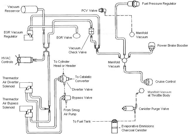
Vacuum control problems:
If someone has misrouted the EGR vacuum plumbing or the EVR (Electronic Vacuum Regulator) has failed, you can get this code.
Diagram courtesy of Tmoss & Stang&2birds
EGR test procedure courtesy of cjones
to check the EGR valve:
bring the engine to normal temp.
connect a vacuum pump to the EGR Valve or
see the EGR test jig drawing below. Connnect the test jig or to directly to manifold vacuum.
Do not connect the EGR test jig to the EVR (Electronic Vacuum Regulator).
apply 5in vacuum to the valve.
Using the test jig, use your finger to vary the vacuum
if engine stumbled or died then EGR Valve and passage(there is a passageway through the heads and intake) are good.
if engine did NOT stumble or die then either the EGR Valve is bad and/or the passage is blocked.
if engine stumbled,
connect EGR test jig to the hose coming off of the EGR Valve.
Use your finger to cap the open port on the vacuum tee.
snap throttle to 2500 RPM (remember snap the throttle don't hold it there).
did the vacuum gauge show about 2-5 in vacuum?
if not the EVR has failed
EGR test jig
If the blow by test passes, and you have replaced the sensor, then you have electrical ground problems. Check the resistance between the black/white wire on the MAP/BARO sensor and then the black/white wire on the EGR and the same wire on the TPS. It should be less than 1.5 ohm. Next check the resistance between the black/white wire and the negative battery post. It should be less than 1.5 ohm.
Note that all resistance tests must be done with power off. Measuring resistance with a circuit powered on will give false readings and possibly damage the meter.
Let’s put on our Inspector Gadget propeller head beanies and think about how this works:
The EGR sensor is a variable resistor with ground on one leg and Vref (5 volts) on the other. Its’ resistance ranges from 4000 to 5500 Ohms measured between Vref & ground, depending on the sensor. The center connection of the variable resistor is the slider that moves in response to the amount of vacuum applied. The slider has some minimum value of resistance greater than 100 ohms so that the computer always sees a voltage present at its’ input. If the value was 0 ohms, there would be no voltage output. Then the computer would not be able to distinguish between a properly functioning sensor and one that had a broken wire or bad connection. The EGR I have in hand reads 700 Ohms between the slider (EPV) and ground (SIG RTN) at rest with no vacuum applied. The EGR valve or sensor may cause the voltage to be above closed limits due to the manufacturing tolerances that cause the EGR sensor to rest at a higher position than it should.
The following sensors are connected to the white 10 pin connector (salt & pepper engine harness connectors)
This will affect idle quality by diluting the intake air charge
See the following website for some help from Tmoss (diagram designer) & Stang&2Birds (website host) for help on 88-95 wiring Mustang FAQ - Engine Information Everyone should bookmark this site.
Ignition switch wiring
http://www.veryuseful.com/mustang/tech/engine/images/IgnitionSwitchWiring.gif
Fuel, alternator, A/C and ignition wiring
http://www.veryuseful.com/mustang/tech/engine/images/fuel-alt-links-ign-ac.gif
Complete computer, actuator & sensor wiring diagram for 88-91 Mass Air Mustangs
http://www.veryuseful.com/mustang/tech/engine/images/88-91_5.0_EEC_Wiring_Diagram.gif
Complete computer, actuator & sensor wiring diagram for 91-93 Mass Air Mustangs
http://www.veryuseful.com/mustang/tech/engine/images/91-93_5.0_EEC_Wiring_Diagram.gif
Complete computer, actuator & sensor wiring diagram for94-95 Mass Air Mustangs
http://www.veryuseful.com/mustang/tech/engine/images/94-95_5.0_EEC_Wiring_Diagram.gif
Vacuum diagram 89-93 Mustangs
http://www.veryuseful.com/mustang/tech/engine/images/mustangFoxFordVacuumDiagram.jpg
HVAC vacuum diagram
http://www.veryuseful.com/mustang/tech/engine/images/Mustang_AC_heat_vacuum_controls.gif
TFI module differences & pinout
http://www.veryuseful.com/mustang/tech/engine/images/TFI_5.0_comparison.gif
Fuse box layout
http://www.veryuseful.com/mustang/tech/engine/images/MustangFuseBox.gif
Code 66 MAF below minimum test voltage.
Insufficient or no voltage from MAF. Dirty MAF element, bad MAF, bad MAF wiring, missing power to MAF. Check for missing +12 volts on this circuit. Check the two links for a wiring diagram to help you find the red wire for computer power relay switched +12 volts. Check for 12 volts between the red and black wires on the MAF heater (usually pins A & B). while the connector is plugged into the MAF. This may require the use of a couple of safety pins to probe the MAF connector from the back side of it.
There are three parts in a MAF: the heater, the sensor element and the amplifier. The heater heats the MAF sensor element causing the resistance to increase. The amplifier buffers the MAF output signal and has a resistor that is laser trimmed to provide an output range compatible with the computer's load tables.
If you have a K&N flat panel filter or other filter that requires oiling, excess oil may coat the MAF sensor element and cause problems.
The MAF element is secured by 2 screws & has 1 wiring connector. To clean the element, remove it from the MAF housing and spray it down with electronic parts cleaner or non-inflammable brake parts cleaner (same stuff in a bigger can and cheaper too).
Changes in RPM causes the airflow to increase or decease, changing the voltage output.. The increase of air across the MAF sensor element causes it to cool, allowing more voltage to pass and telling the computer to increase the fuel flow. A decrease in airflow causes the MAF sensor element to get warmer, decreasing the voltage and reducing the fuel flow. Measure the MAF output at pins C & D on the MAF connector (dark blue/orange and tan/light blue) or at pins 50 & 9 on the computer. Be sure to measure the sensor output by measuring across the pins and not between the pins and ground.
At idle = approximately .6 volt
20 MPH = approximately 1.10 volt
40 MPH = approximately 1.70 volt
60 MPH = approximately 2.10 volt
Check the resistance of the MAF signal wiring. Pin D on the MAF and pin 50 on the computer (dark blue/orange wire) should be less than 2 ohms. Pin C on the MAF and pin 9 on the computer (tan/light blue wire) should be less than 2 ohms.
There should be a minimum of 10K ohms between either pin C or D on the MAF wiring connector and ground. Make your measurement with the MAF disconnected from the wiring harness.
See the following website for some help from Tmoss (diagram designer) & Stang&2Birds (website host) for help on 88-95 wiring
http://www.veryuseful.com/mustang/tech/engine/
Ignition switch wiring
http://www.veryuseful.com/mustang/tech/engine/images/IgnitionSwitchWiring.gif
Fuel pump, alternator, ignition & A/C wiring
http://www.veryuseful.com/mustang/tech/engine/images/fuel-alt-links-ign-ac.gif
Computer,. actuator & sensor wiring
http://www.veryuseful.com/mustang/tech/engine/images/88-91_5.0_EEC_Wiring_Diagram.gif
Fuse panel layout
http://www.veryuseful.com/mustang/tech/engine/images/MustangFuseBox.gif
Vacuum routing
http://www.veryuseful.com/mustang/tech/engine/images/mustangFoxFordVacuumDiagram.jpg
Code 81 – Secondary Air Injection Diverter Solenoid failure AM2. The solenoid valve located on the back side of the passenger side wheel well is not functional. Possible bad wiring, bad connections, missing or defective solenoid valve. Check the solenoid valve for +12 volts at the Red wire and look for the Lt Green/Black wire to switch from +12 volts to 1 volt or less. The computer controls the valve by providing a ground path on the LT Green/Black wire for the solenoid valve.
With the with the ignition on, look for 12 volts on the red wire on the solenoid connector. No 12 volts and you have wiring problems.
With the engine running, stick a safety pin in the LT Green/Black wire for the solenoid valve & ground it. That should turn the solenoid on and cause air to flow out the port that goes to the pipe connected to the cats. If it doesn't, the valve is bad. If it does cause the airflow to switch, the computer or wiring going to the computer is not signaling the solenoid valve to open.
Putting the computer into self test mode will cause the solenoid valve to toggle. If you listen carefully, you may hear it change states.
Code 87 – fuel pump primary circuit failure. The fuel pump lost power while the engine was running. Check fuel pump relay, check inertia switch, wiring to/from inertia switch, red wire going to inertia switch for +12volts. Check the other side of inertia switch for +12 volts.
To help troubleshoot the 87 code, follow this link for a wiring diagram for 89-93 cars
http://www.autozone.com/servlet/UiB..._us/0900823d/80/19/59/5a/0900823d8019595a.jsp
Diagram of the fuel pump wiring for 86-90 cars
Diagram of the fuel pump wiring for 91-93 cars.
Fuel Pump Troubleshooting for 86-90 Mustangs
Clue – listen for the fuel pump to prime when you first turn the ignition switch on.
It should run for 2-5 seconds and shut off. This on and off again cycle helps to prevent
flooding the engine when cranking. To trick the fuel pump into running, find the ECC
test connector and jump the connector in the upper RH corner to ground.
If the fuse links are OK, you will have power to the pump. Check fuel pressure –
remove the cap from the Schrader valve behind the alternator and depress the
core. Fuel should squirt out, catch it in a rag. A tire pressure gauge can also be
used if you have one - look for 37-40 PSI. Beware of fire hazard when you do this.
No fuel pressure, possible failed items in order of their probability:
A.) Tripped inertia switch – press reset button on the inertia switch. The hatch
cars hide it under the plastic trim covering the driver's side taillight. Use the
voltmeter or test light to make sure you have power to both sides of the switch
B.) Fuel pump power relay – located under the driver’s seat in most stangs built
before 92. On 92 and later model cars it is located below the Mass Air Flow meter.
C.) Clogged fuel filter
D.) Failed fuel pump
E.) Blown fuse link in wiring harness.
F.) Fuel pressure regulator failed. Remove vacuum line from regulator and inspect
for fuel escaping while pump is running.
The electrical circuit for the fuel pump has two paths, a control path and a power
path.
The control path consists of the inertia switch, the computer, and the fuel pump
relay coil. It turns the fuel pump relay on or off under computer control. The
switched power (red wire) from the ECC relay goes to the inertia switch
(red/black wire) then from the inertia switch to the relay coil and then from the
relay coil to the computer (tan/ Lt green wire). The computer provides the ground
path to complete the circuit. This ground causes the relay coil to energize and
close the contacts for the power path. Keep in mind that you can have voltage
to all the right places, but the computer must provide a ground. If there is no
ground, the relay will not close the power contacts.
The power path picks up from a fuse link near the starter relay. Fuse links are like
fuses, except they are pieces of wire and are made right into the wiring harness.
The feed wire from the fuse link (orange/ light blue wire) goes to the fuel pump
relay contacts. When the contacts close because the relay energizes, the power
flows through the contacts to the fuel pump (light pink/black wire). Notice that
pin 19 on the computer is the monitor to make sure the pump has power.
The fuel pump has a black wire that supplies the ground to complete the circuit.
Remember that the computer does not source any power to actuators, relays
or injectors, but provides the ground necessary to complete the circuit. That
means one side of the circuit will always be hot, and the other side will go to
ground or below 1 volt as the computer switches on that circuit.
Diagram courtesy of AutoZone
Now that you have the theory of how it works, it’s time to go digging.
Look for 12 volts at the Orange/Lt. Blue wire (power source for fuel pump relay).
No voltage or low voltage, bad fuse link, bad wiring, bad ignition switch or ignition
switch wiring or connections. There is a mystery connector somewhere under the
driver’s side kick panel, between the fuel pump relay and the fuse link.
Turn on the key and jumper the fuel pump test connector to ground as previously
described. Look for 12 volts at the Light Pink/Black wire (relay controlled power
for the fuel pump). No voltage there means that the relay has failed, or there is a
broken wire in the relay control circuit.
Check the Red/black wire, it should have 12 volts. No 12 volts there, either the
inertia switch is open or has no power to it. Check both sides of the inertia
switch: there should be power on the Red wire and Red/Black wire. Power on the
Red wire and not on the Red/Black wire means the inertia switch is open.
Make sure that the power is off the circuit before making any resistance checks.
If the circuit is powered up, your resistance measurements will be inaccurate.
You will have to drop the tank to inspect the pump power and ground connector
and the pump wiring chassis ground.
Pump wiring: Anytime the ignition switch is in the Run position and the test
point is jumpered to ground, there should be at least 12 volts present on the
black/pink wire. You should see less than 1 Ohm between the black wire(s)
and ground. The chassis ground is up near the spare tire shell. To get some
idea of what a good reading is, short the two meter leads together and
observe the reading. It should only be slightly higher when you measure
the black wire to ground resistance.
The Tan/Lt Green wire provides a ground path for the relay power. With the test
connector jumpered to ground, there should be less than .75 volts. Use a test
lamp with one side connected to battery power and the other side to the
Tan/Lt Green wire. The test light should glow brightly. No glow and you have a
broken wire or bad connection between the test connector and the relay. To test
the wiring from the computer, remove the passenger side kick panel and
disconnect the computer connector. It has a 10 MM bolt that holds it in place.
With the test lamp connected to power, jumper pin 22 to ground and the test
lamp should glow. No glow and the wiring between the computer and the fuel
pump relay is bad.
Computer: If you got this far and everything else checked out good, the computer is suspect.
Remove the test jumper from the ECC test connector located under the hood.
Probe computer pin 22 with a safety pin and ground it to chassis. Make sure the computer
and everything else is connected. Turn the ignition switch to the Run position and observe
the fuel pressure. The pump should run at full pressure.
If it doesn't, the wiring between pin 22 on the computer and the fuel pump relay is bad.
If it does run at full pressure, the computer may have failed.
Keep in mind that the computer only runs the fuel pump for about 2-3 seconds when you turn
the key to the Run position. This can sometimes fool you into thinking the computer has died.
Connect one lead of the test light to power and the other lead to computer pin 22 with a safety pin.
With the ignition switch Off, jumper the computer into self test mode like you are going to dump
the codes. Turn the ignition switch to the Run position. The light will flicker when the computer
does the self test routine. A flickering light is a good computer. No flickering light is a bad computer.
Remove the test jumper from the ECC test connector located under the hood.
Fuel pump runs continuously: The fuel pump relay contacts are stuck together or the Tan/Lt Green wire
has shorted to ground. Remove the fuel pump relay from its socket. Then disconnect the computer and use
an ohmmeter to check out the resistance between the Tan/Lt Green wire and ground. You should see
more than 10 K Ohms (10,000 ohms) or an infinite open circuit. Be sure that the test connector isn’t
jumpered to ground.
If the wiring checks out good, then the computer is the likely culprit.
Prior to replacing the computer, check the computer power ground. The computer has its own
dedicated power ground that comes off the ground pigtail on the battery ground wire. Due to
it's proximity to the battery, it may become corroded by acid fumes from the battery. It is a
black cylinder about 2 1/2" long by 1" diameter with a black/lt green wire. You'll find it up
next to the starter solenoid where the wire goes into the wiring harness
If all of the checks have worked OK to this point, then the computer is bad. The
computers are very reliable and not prone to failure unless there has been
significant electrical trauma to the car. Things like lightning strikes and putting
the battery in backwards or connecting jumper cables backwards are about the
only thing that kills the computer.
See the following website for some help from Tmoss (diagram designer) &
Stang&2Birds (website host)
http://www.veryuseful.com/mustang/tech/engine/images/IgnitionSwitchWiring.gif
http://www.veryuseful.com/mustang/tech/engine/images/fuel-alt-links-ign-ac.gif
http://www.veryuseful.com/mustang/tech/engine/images/88-91eecPinout.gif