Calling EDBERT - Gauge upgrade!!

geostang351

Member
Mar 30, 2005
946
0
17
Danb., CT
Edbert,
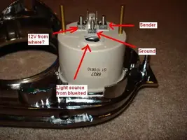
I am moving steadily with the Autometer gauge upgrade to my 68 coupe and have a question concerning the wiring of the gauges. The gauges each have three connections at the rear: 1. for ground, 2. for sending unit and the 3rd for 12V power. I have no problems with the first two but I am wondering where you have gained the 12V required for these gauges. I am using the blue w/red stripe wire for meter lights (shown as black and white wires at rear of autometer gauges).
THe old gauges have two connections at the rear. I assume one is for the sender and the other is for ground (???) This wire for ground is the typical color of black with a white stripe for all electric gauges on my hold gauge harness. Or am I incorrect and the black w/white stripe wire is the 12V source and the gauge is grounded by direct contact with the backing plate.
Can you please clarify where to get the 12 volt source and what the black w/white stripe wire is specifically (ground or power)
Thanks :nice: :nice:

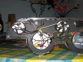
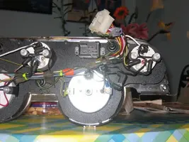
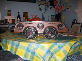
DSC00419.jpg


DSC00119.jpg


DSC00433.jpg
 
Wow that looks awesome.

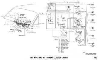
I have a wiring diagram in front of me, and I can tell you that the blue with red stripe is the 12v for the dash panel lights. Let me digest the diagram a little and I might be able to tell you where the other ones go....

Edit: Nevermind. I see that is not what you are asking. According to the diagram the black w/white stripe goes from the temp then to fuel, then to the "constant voltage unit". Another black w/white goes from the oil temp to the cvu. A black with green stripe then goes from the cvu to the wiring harness. So yeah maybe that is the 12V? Did you test it with a meter?

I don't know if this helps or not, I am just getting into the wiring system of my car and bought this diagram years ago. I think I picked it up last night for the first time.
 
The only stock wiring I kept is for the turn signal indicators and high beam indicator. The Autometers use internal lights, so there's no point in using the stock illumination system at all, except for the hot lead. use it to provide power to each of the new ones and you should be fine on lights. For actual gauge source (from senders) I ran all new wiring since I am running the painless kit. I have about 2.5 feet of factory wring left on my car, mostly for the specialized connectors like the turn signal indicators etc.
 
Edbert, I'm not having any issue with the lights within the gauges. I'll be useing the stock wire (blue w/red strip) for their power. My problem is there are three conections at the rear of the gauge. Ground (no problem) sending unit wire (no problem) but there is a third terminal asking for a 12v volt source. Where did you tap into to obtain your power source? What is the black w/white stripe wire used for at the back of all factory gauges as BIG_B mentions above? COnstant voltage unit? what is that?
 
So then it sounds like you can use the blue/red for power? Is that a 12V line? Also from here: (http://en.allexperts.com/q/Ford-Repair-811/constant-voltage-unit-instrument.htm) it looks like the "CVU" only puts out 6 volts (in a 66 anyway).

Geo - I know when I installed a stereo years ago I just hunted around underneath the dash for a 12v using a multimeter. Sounds like Edbert gutted his harness, which is different from what you are doing.
 
So then it sounds like you can use the blue/red for power? Is that a 12V line? Also from here: (http://en.allexperts.com/q/Ford-Repair-811/constant-voltage-unit-instrument.htm) it looks like the "CVU" only puts out 6 volts (in a 66 anyway).
I would, however the blue/red wire will be the power for my instrument lights which requires a separate 12v source.

Geo - I know when I installed a stereo years ago I just hunted around underneath the dash for a 12v using a multimeter. Sounds like Edbert gutted his harness, which is different from what you are doing.
Edbert seems pretty electrically inclined so I thought I'd ask if he knew what the purpose of the black/white wire was. Edbert used the painless kit but still used the same gauges as me. I was wondering how he tied into his power source for the required gauges.
Four of the gauages are electrical and I'm trynig to prevent running 4 seperate lines to the fuse panel.
 
There are two different sources of power here that you want to use, note you don't HAVE to use one and not the other, but let me explain the difference...

One is powered whenever the ignition curcuit is hot, that is the one you WANT to use to power the gauges themselves.

One is powered from the headlight switch and is only hot when the parking lights are on, that is the one you WANT to use for the lighting.

There is an always hot circuit in there too, you do NOT want to use that one for anything in my opinion, except arguably the stereo. Note; it connects to the headlight switch, that is why you can turn on your lights with the key removed. So be sure which one you are using for the lighting.
 
I'd run new line from the ingition switch, use the terminal on that switch that is hot when the key is in all positions except "off" (straight up). That way when the key is turned to run/start/accessory your gauges should work, but when it is off they wont draw any current and drain your battery.

I have no idea what the color of the factory wire that does that is, there almost no factory wiring left on my car.
 
Feel free to use my write-up. Reen credited me with inspiring him with his 67-68 mod, but frankly his method is MUCH more professional than mine. Anyhow, as has been mentioned here I did not use the factory wiring harness, I opted to replace all of the old brittle wiring and replace it. There are some drawing on that page that might help you out too.

GAUGE POD MOD

WIRING HARNESS
 
Hi.
When I did my gauge conversion I just used the stock harness, each of the stock gauges has its own power lead black/green, i just transferred them to the autometer's, if you compress the stock connector slightly it will fit nicely on the autometer round contact post.
Also water sender was red/white, oil pressure white/red and fuel was yellow/white, been working fine past 6 months. I would post pic's but didn't realize i needed to have them hosted somewhere, once i figured that out i will post them if interested.
Steve
 
Nice work Steve!! :flag: I see you went with the smaller gauges and used the brakets from the gauges to hold your gauges in place. I used the larger gauages (2 5/8") and secured them with screws which called for some "mesaging " of the bezel and rear securing plate.
From your picture, it appears that the black w/green stripe is the power source for your gauges to operate (The reason I say that is the water temp, oil pressure and fuel gauge all have this wire running to it. Being that your car is possibly an earlier model, I can only assume that ford changed the wire color to black w/white stripe in 68 from black/green in 67.

What year is your car?

Thanks for the pictures too!!!! :nice:
 
Sorry man, I cut mine up and chucked it. I have the entire 67 factory wiring diagrams on my site though. Since they are not my copyright feel free to take them.

ClickHERE to see them all, the ones that start with "67" are the ones you want. But I'm afraid there is not full detail of the dash section that also has color descriptions of the ones you want (I already tried to look it up for you).
 
Sorry man, I cut mine up and chucked it. I have the entire 67 factory wiring diagrams on my site though. Since they are not my copyright feel free to take them.

ClickHERE to see them all, the ones that start with "67" are the ones you want. But I'm afraid there is not full detail of the dash section that also has color descriptions of the ones you want (I already tried to look it up for you).

Do you think this is something that'll help? I've been trying to print it out but can only get half the page to print. Figures

http://www.hammar.dyndns.org/~djhamma/wiring/wiring1967.htm