Code 29 - Vehicle Speed Sensor (VSS) is an electronic sender mounted on the speedo pickup gear on the trans. It works the cruse control for both 5 speed and auto trans cars. The VSS is used to tell the computer to speed up the idle as you slow to a stop. This helps keep the engine from stalling when you slow down for a stop sign or stop light.
Check to see if the electrical connector is plugged into it. Clean the connector & contacts with non flammable brake parts cleaner prior to replacing the sensor, as that may fix the problem. The sensor cost is under $30 and it is easy to replace.
CODE: 31 (KOEO) - EVP circuit below minimum voltage. Vref (5 volt reference voltage supplied by the computer) missing or broken wire or bad connection in circuit.
Revised 06-Aug-2016 to add clarification of the 10 pin connector possible problems
Use a DVM to check for 5 volts on the orange/white wire. If it is missing, look for +5 volts at the orange/white wire on the TPS or MAP sensor located on the firewall near the center of the car. Use the black/white wire for the ground for the DVM.
With the sensor removed from the EGR and still connected, press the plunger and watch the voltage change on the brown/lt green wire. Pull the passenger side kick panel and measure the voltage at the computer. You will need to remove the plastic cover over the wires and probe them from the backside. A safety pin may prove very useful for this task. Use pin 27, EVR input (brown/lt green wire) and pin 46, signal ground (black/white wire) to measure the voltage. The orange/white wire is VREF and should always be 5 volts -/+ .25 volt. Be sure to measure VREF at the EGR sensor to rule out any broken wires or bad connections.
Measuring the voltage at the computer helps you spot broken wiring and intermittent connections. The 10 pin connectors are especially prone to connection problems, If the voltage checks at the EGR sensor are good but not at the computer, the 10 pin connector is suspect.
See the graphic for the 10 pin connector circuit layout.
Computer wiring harness connector, wire side
Computer wiring harness connector, computer side
Code 54 – ACT sensor out of range. Broken or damaged wiring, bad ACT sensor. Note that that if the outside air temp is below 50 degrees F that the test for the ACT can be in error.
Check the resistance of the black/white wire to battery ground. If it is less than 2 ohms, it is good. If it is more than 2 ohms, the black/white wire has bad connections or a broken wire. Always take resistance measurements with the circuit powered off.
See the graphic for the 10 pin connector circuit layout.
Then check the resistance of the ACT sender located in the #5 intake runner on most 5.0 stangs.
ACT & ECT test data:
The ACT & ECT have the same thermistor, so the table values are the same
Pin 7 on the computer - ECT signal in. at 176 degrees F it should be .80 volts
Pin 25 on the computer - ACT signal in. at 50 degrees F it should be 3.5 volts. It is a good number if the ACT is mounted in the inlet airbox. If it is mounted in the lower intake manifold, the voltage readings will be lower because of the heat transfer. Here's the table :
68 degrees F = 3.02 v
86 degrees F = 2.62 v
104 degrees F = 2.16 v
122 degrees F = 1.72 v
140 degrees F = 1.35 v
158 degrees F = 1.04 v
176 degrees F = .80 v
194 degrees F = .61
Ohms measures at the computer with the computer disconnected, or at the sensor with the sensor disconnected.
50 degrees F = 58.75 K ohms
68 degrees F = 37.30 K ohms
86 degrees F = 27.27 K ohms
104 degrees F = 16.15 K ohms
122 degrees F = 10.97 K ohms
140 degrees F = 7.60 K ohms
158 degrees F = 5.37 K ohms
176 degrees F = 3.84 K ohms
194 degrees F = 2.80 K ohms
Code 66 or 157 MAF below minimum test voltage.
Revised 2 Nov 2019 to add details on MAF testing
Insufficient or no voltage from MAF. Dirty MAF element, bad MAF, bad MAF wiring, missing power to MAF. Check for missing +12 volts on this circuit. Check the two links for a wiring diagram to help you find the red wire for computer power relay switched +12 volts. Check for 12 volts between the red and black wires on the MAF heater (usually pins A & B). while the connector is plugged into the MAF. This may require the use of a couple of safety pins to probe the MAF connector from the back side of it.
Computer wiring harness connector, wire side.
Computer wiring harness connector, computer side.
Diagrams courtesy of Tmoss and Stang&2Birds
ECC Diagram for 88-90 5.0 Mustangs
ECC Diagram for 91-93 5.0 Mustangs
94-95 Diagram for 94-95 5.0 Mustangs[/b]
How the MAF works
There are three parts in a MAF: the heater, the sensor element and the amplifier. The heater heats the MAF sensor element causing the resistance to increase. The amplifier buffers the MAF output signal and has a resistor that is laser trimmed to provide an output range compatible with the computer's load tables. Changes in RPM causes the airflow to increase or decrease, changing the voltage output. The increase of air across the MAF sensor element causes it to cool, allowing more voltage to pass and telling the computer to increase the fuel flow. A decrease in airflow causes the MAF sensor element to get warmer, decreasing the voltage and reducing the fuel flow.
Actually, MAF pins C & D float with reference to ground. The signal output of the MAF is a differential amplifier setup. Pins C & D both carry the output signal, but one pin's output is inverted from the other. The difference in signal between C & D is what the computer's input circuit is looking for. The difference in the two outputs helps cancel out electrical noise generated by the ignition system and other components. Since the noise will be of the same polarity, wave shape and magnitude, the differential input of the computer electronically subtracts it from the signal. Then it passes the signal on to an Analog to Digital converter section inside the computer's CPU chip.
The MAF element is secured by 2 screws & has 1 wiring connector. To clean the element, remove it from the MAF housing and spray it down with electronic parts cleaner or non-inflammable brake parts cleaner (same stuff in a bigger can and cheaper too).
89-90 Model cars: Measure the MAF output at pins C & D on the MAF connector (dark blue/orange and tan/light blue) or at pins 50 & 9 on the computer.
Be sure to measure the sensor output by measuring across the pins and not between the pins and ground.
91-95 Model cars: Measure the MAF output at pins C & D on the MAF connector light blue/red and tan/light blue) or at pins 50 & 9 on the computer.
Be sure to measure the sensor output by measuring across the pins and not between the pins and ground.
MAF output readings: Use the computer connector diagram to help choose the proper pin connection on the computer when measuring the MAF output voltage. The idling voltage check can the done with the voltmeter directly stuck in the backside of the MAF connector.
At idle = approximately .6 volt
20 MPH = approximately 1.10 volt
40 MPH = approximately 1.70 volt
60 MPH = approximately 2.10 volt
If the output of the C&D pins exceeds the specs above, there are two possible problems:
1.) The MAF sensor is defective and needs to be replaced.
2.) The MAF sensor is installed in a different housing than the one it was designed for. The sensor is designed to work with a specific MAF part number or model MAF housing.
Check the resistance of the MAF signal wiring
For the next 2 checks make your measurement with the MAF disconnected from the wiring harness.
Pin D on the MAF wiring harness and pin 50 on the computer (dark blue/orange wire) should be less than 2 ohms. Pin C on the MAF wiring harness and pin 9 on the computer (tan/light blue wire) should be less than 2 ohms.
There should be a minimum of 10K ohms between either pin C or D on the MAF wiring connector and pins A or B.
Reconnect the MAF to the wiring harness and proceed to the next section.
See the following website for some help from Tmoss (diagram designer) & Stang&2Birds (website host) for help on 88-95 wiring
http://www.veryuseful.com/mustang/tech/engine/
Ignition switch wiring
http://www.veryuseful.com/mustang/tech/engine/images/IgnitionSwitchWiring.gif
Fuel pump, alternator, ignition & A/C wiring
http://www.veryuseful.com/mustang/tech/engine/images/fuel-alt-links-ign-ac.gif
Computer, actuator & sensor wiring
http://www.veryuseful.com/mustang/tech/engine/images/88-91_5.0_EEC_Wiring_Diagram.gif
Fuse panel layout
http://www.veryuseful.com/mustang/tech/engine/images/MustangFuseBox.gif
Vacuum routing
http://www.veryuseful.com/mustang/tech/engine/images/mustangFoxFordVacuumDiagram.jpg
Code 82 – Secondary Air Injection Diverter Solenoid failure AM1. Possible bad wiring, bad connections, missing or defective solenoid valve. Check the solenoid valve for +12 volts at the Red wire and look for the Red/White wire to switch from +12 volts to 1 volt or less. The computer controls the valve by providing a ground path on the Red/White wire for the solenoid valve
With the engine running, stick a safety pin in the Red/White wire for the solenoid valve & ground it. That should turn the solenoid on and cause air to flow out the port that goes to the pipe connected to the heads. If it doesn't, the valve is bad. If it does cause the airflow to switch, the computer or wiring going to the computer is not signaling the solenoid valve to open.
Both 81 & 82 codes usually mean that some uneducated person removed the solenoid control valves for the Thermactor Air system in an attempt to make the car faster. It doesn't work that way: no working control valves can cause the cat converters to choke and clog. If you do not have cat converters on the car, you can ignore the 81 & 82 codes.
Code 85 CANP solenoid - The Carbon Canister solenoid is inoperative or missing.
Revised 11 –Jan_2015 to add warning about vacuum leaks due to deteriorated hose or missing caps on vacuum lines when the solenoid is removed.
Check vacuum lines for leaks and cracks.
If the vacuum line that comes from under the upper manifold is missing or is not connected to the canister solenoid valve, you will have a huge vacuum leak. That will upset the air/fuel ratio and cause performance and drivability problems.
Check electrical wiring for loose connections, damaged wiring and insulation. Check solenoid valve operation by grounding the gray/yellow wire to the solenoid and blowing through it.
The computer provides the ground for the solenoid. The red wire to the solenoid is always energized any time the ignition switch is in the run position.
If you disconnected the carbon canister and failed to properly cap the vacuum line coming from under the upper intake manifold, you will have problems. You will also have problems if the remaining hose coming from under the upper intake manifold or caps for the vacuum line are sucking air.
Charcoal canister plumbing - one 3/8" tube from the bottom of the upper manifold to the rubber hose. Rubber hose connects to one side of the canister solenoid valve. Other side of the solenoid valve connects to one side of the canister. The other side of the canister connects to a rubber hose that connects to a line that goes all the way back to the gas tank. There is an electrical connector coming from the passenger side injector harness near #1 injector that plugs into the canister solenoid valve. It's purpose is to vent the gas tank. The solenoid valve opens at cruse to provide some extra fuel. The canister is normally mounted on the passenger side frame rail near the smog pump pulley.
Connecting the gas tank vent line directly to the intake manifold will result in fuel vapor being constantly sucked into the intake manifold. There is unmetered fuel that the computer cannot adjust for. The result is poor idle and poor fuel economy.
It does not weigh but a pound or so and helps richen up the cruse mixture. It draws no HP & keeps the car from smelling like gasoline in a closed garage. So with all these good things and no bad ones, why not hook it up & use it?
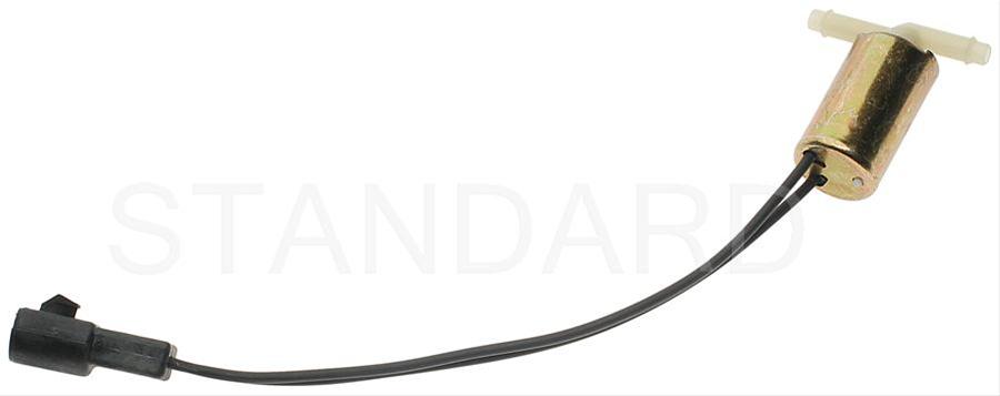
The purge valve solenoid connector is a dangling wire that is near the ECT sensor and oil filler on the passenger side rocker cover. The actual solenoid valve is down next to the carbon canister. There is about 12"-16" of wire that runs parallel to the canister vent hose that comes off the bottom side of the upper intake manifold. That hose connects one port of the solenoid valve; the other port connects to the carbon canister.
The purge valve solenoid should be available at your local auto parts store.
Purge valve solenoid:
The carbon canister is normally mounted on the passenger side frame rail near the smog pump pulley.
Carbon Canister: