
You are using an out of date browser. It may not display this or other websites correctly.
You should upgrade or use an alternative browser.
You should upgrade or use an alternative browser.
Code 12,21,41,91, now 12,42,92
- Thread starter Luis911
- Start date
Code 12 -Idle Air Bypass motor not controlling idle properly (generally idle too low) - IAB dirty or not working. Take it off and clean it thoroughly with throttle body cleaner. Clean the electrical contacts with non flammable brake parts cleaner at the same time.
Code 42 & 92 (running) System rich - Fuel control or (memory) System was rich for 15 seconds or more (no HO2S switching) - Fuel control. Look for leaking injectors, fuel pressure too high, cylinder(s) not firing due to bad ignition.
Since the O2 sensors were the last thing you replaced, they may be defective. The parts guy may have given you the wrong ones, or the new ones are bad out of the box.
xpeteyjtx
New Member
It seems kinda weird how you got rid of code 21, 41, and 91 by just replacing O2s.
code 21 is the ECT, by the way.
When take the engine running test, make sure its been running for a while so it is at normal running temp.
But yea, return those O2s and get some new ones like jrichker said.
code 21 is the ECT, by the way.
When take the engine running test, make sure its been running for a while so it is at normal running temp.
But yea, return those O2s and get some new ones like jrichker said.
To start, you had an idle problem where the IAC was not able to bring the rpm as high as it needed to go, along with a lean code, and an Engine coolant temp problem. Check your t-stat, what degree are you running, and make sure it is opening at the proper temprature. If so, and the coolant is good, maby the engine coolant temprature sensor needs replacment first. The O2's were reading lean, and they probally weren't the issue, but now that you trew parts at it, now the problem got more complex. Once you take care of the ECT, then concentrate on the other sensors.
Thanks, my english is limited. My mustang timing 12º. I have others problems, 1 spark wet whit oil and i have blue smoke, also, when I adjusted "resetting the base idle" (www.muscularmustangs.com/idlereset.php) only is 800 RPM and after I adjust TPS whith 0.985 Volts, I tried a lot values, and the engine is cold RPM=800 but engine is warm always is in ~1000 RPM (other values was 850 Cold and 950 Warm, 900 cold and 1050 warm aprox.)
Mustang 1981 Conversion 1990 (but system MAP 1988 ) 5.0 HO, 5 vel. + reverse. EFI
Mustang 1981 Conversion 1990 (but system MAP 1988
) 5.0 HO, 5 vel. + reverse. EFIjrichker said:Code 12 -Idle Air Bypass motor not controlling idle properly (generally idle too low) - IAB dirty or not working. Take it off and clean it thoroughly with throttle body cleaner. Clean the electrical contacts with non flammable brake parts cleaner at the same time.
Code 42 & 92 (running) System rich - Fuel control or (memory) System was rich for 15 seconds or more (no HO2S switching) - Fuel control. Look for leaking injectors, fuel pressure too high, cylinder(s) not firing due to bad ignition.
Since the O2 sensors were the last thing you replaced, they may be defective. The parts guy may have given you the wrong ones, or the new ones are bad out of the box.
Thanks, Yesterday I checked codes, and now I have Code 12,21 and 16, this is normal???
xpeteyjtx
New Member
Go HERE for a list of what the codes mean.
Are you getting the codes with the Engine Off or On? Pull the codes with both the Engine On and Off, so that you have a better idea of what is going on. Have you cleaned your TB (code 12) like jrichker suggested? It seems like you need to check some grounds and connections, and then possibly, replace some sensors. Whenever I mess with connections, I always apply dielectrical grease to the pins/connectors... it helps prevent corrosion and stuff like that. Good luck.
Are you getting the codes with the Engine Off or On? Pull the codes with both the Engine On and Off, so that you have a better idea of what is going on. Have you cleaned your TB (code 12) like jrichker suggested? It seems like you need to check some grounds and connections, and then possibly, replace some sensors. Whenever I mess with connections, I always apply dielectrical grease to the pins/connectors... it helps prevent corrosion and stuff like that. Good luck.
xpeteyjtx said:Go HERE for a list of what the codes mean.
Are you getting the codes with the Engine Off or On? Pull the codes with both the Engine On and Off, so that you have a better idea of what is going on. Have you cleaned your TB (code 12) like jrichker suggested? It seems like you need to check some grounds and connections, and then possibly, replace some sensors. Whenever I mess with connections, I always apply dielectrical grease to the pins/connectors... it helps prevent corrosion and stuff like that. Good luck.
"Engine Off" I was this code:
CODE 85 Canister purge circuit or transmission shift control circuit
CODE 85 Canister purge circuit
I buyed solenoid (E4ZF-9C915-A) and problem solve.
"Engine On"
CODE 12, 21 and 16
I cleaned TB, my IAC I buyed since 3 months old.
Question: When Engine is cold, RPM=800-850, when is warming RPM=950, when is 1/2 indicator Temp RPM=1050 aprox. this is normal or always RPM=value?????
Thanks
xpeteyjtx
New Member
Code 21-> do you have a 160 degree thermo?? If you do, then this is why you are getting this code. If you engine is running at an ideal temperature (180-200) while you are testing it and you get code 21, then you probably need a new ECT sensor. I dont know where the ECT sensor is, so I cant help you there. You would also get code 21 if the coolant was very warm... over 250 degrees I believe.
I Checked o2 sensors with a friend and say these Ok.
Now, I have these codes:
KOEO:
Code 64 = Intake Air Temperature (IAT) or Vane Air Temperature (VAT) signal low or grounded - IAT VAT
(other code 64 = ACT indicated 254degF; circuit grounded.) Is ok?????
KOER:
Code 12, 42 and 92.
With engine cold I checked ACT sensor with 22.9 K OHMS (I have table says 86ºF 30ºC ~ 24.27 K Ohms). This is method is good known if ACT is ok???
Thanks
Luis911 said:I Checked o2 sensors with a friend and
say these Ok.
Now, I have these codes:
KOEO:
Code 64 = Intake Air Temperature (IAT) or Vane Air
Temperature (VAT) signal low or grounded - IAT VAT
(other code 64 = ACT indicated 254degF; circuit
grounded.) Is ok?????
KOER:
Code 12, 42 and 92.
With engine cold I checked ACT sensor with 22.9 K OHMS
(I have table says 86ºF 30ºC ~ 24.27 K Ohms). This is
method is good known if ACT is ok???
Thanks
The code 64 means that either you have wiring problems
or the ACT sensor element has shorted to the metal case it
is mounted in. Remove the ACT sensor and check the
resistance between the metal threads and the electrical
contacts. You should see more that 1 megohm (1 million
ohms). If the sensor is OK, then you have wiring problems.
Diagram courtesy of Tmoss & Stang&2birds
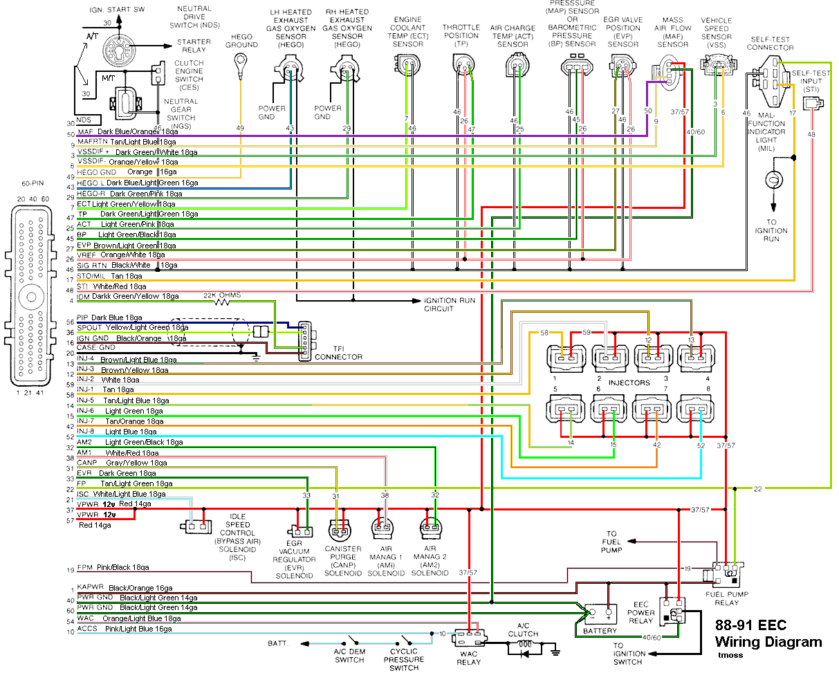
Remove the passenger side kick panel and disconnect the
computer connector by loosening the 10 MM bolt. If you
try to do the next tests without disconnecting the
computer connector, yo will get false readings.
Then check the resistance between ground and the
lt green/pink wire on the ACT socket. You should see more
that 1 megohm (1 million ohms). Be careful and don't
touch the metal part of the meter leads or you'll get a false
reading. Then measure the end to end resistance of the
lt green/pink wire on the ACT socket and pin 25 on the
computer connector. You should see less than 1.5 ohms.
See the following website for some help from Tmoss
(diagram designer) & Stang&2Birds (website host) for
help on 88-95 wiring
http://www.veryuseful.com/mustang/tech/engine
http://www.veryuseful.com/mustang/tech/engine/images/IgnitionSwitchWiring.gif
http://www.veryuseful.com/mustang/tech/engine/images/fuel-alt-links-ign-ac.gif
http://www.veryuseful.com/mustang/tech/engine/images/88-91eecPinout.gif
Aaron'S'tang
New Member
Luis911 said:I was code 12, 21, 41 and 91, I buy o2 sensors and now have code 12, 42 and 92.
Thanks
How can I check my car out?? Can't you use a paperclip or something? Thanks.
jrichker said:The code 64 means that either you have wiring problems
or the ACT sensor element has shorted to the metal case it
is mounted in. Remove the ACT sensor and check the
resistance between the metal threads and the electrical
contacts. You should see more that 1 megohm (1 million
ohms). If the sensor is OK, then you have wiring problems.
Diagram courtesy of Tmoss & Stang&2birds
Remove the passenger side kick panel and disconnect the
computer connector by loosening the 10 MM bolt. If you
try to do the next tests without disconnecting the
computer connector, yo will get false readings.
Then check the resistance between ground and the
lt green/pink wire on the ACT socket. You should see more
that 1 megohm (1 million ohms). Be careful and don't
touch the metal part of the meter leads or you'll get a false
reading. Then measure the end to end resistance of the
lt green/pink wire on the ACT socket and pin 25 on the
computer connector. You should see less than 1.5 ohms.
See the following website for some help from Tmoss
(diagram designer) & Stang&2Birds (website host) for
help on 88-95 wiring
http://www.veryuseful.com/mustang/tech/engine
http://www.veryuseful.com/mustang/tech/engine/images/IgnitionSwitchWiring.gif
http://www.veryuseful.com/mustang/tech/engine/images/fuel-alt-links-ign-ac.gif
http://www.veryuseful.com/mustang/tech/engine/images/88-91eecPinout.gif
I have good and bad news

I checked ACT and connections and ground and ok, also fixed my radiator and temp until first mark whit engine warm
. Today driving my mustang for 1 hour and temp until first mark and check codes, give me this values:KOEO:
First test -- Code 11

")
Second test -- Code 11
KOER:
First test -- Code 12, 42 and 92
Second test -- Code 12, 21, 42 and 92

Third test -- Code 12, 21, 42 and 92
WHY?????????
I check vacuum lines and the things of this message and nothing.
I removed injectors and in the laboratary say all ok, only changed all micro filter.
My codes now:
KOEO: Code 11, code 11 and code 34
KOER: Code 12, code 41 and code 91 WHY??????, any connection bad when removed injectors???
I removed injectors and in the laboratary say all ok, only changed all micro filter.
My codes now:
KOEO: Code 11, code 11 and code 34
KOER: Code 12, code 41 and code 91
WHY??????, any connection bad when removed injectors???Vacuum leak or a bad electical connection could have casued a code 41/91. Both of those could have been fixed when you removed & reinstalled the injectors.
Code 34 Or 334 - EGR voltage above closed limit - Failed sensor, carbon between EGR pintle valve and seat holding the valve off its seat. Remove the EGR valve and clean it with carbon remover. Prior to re-installing see if you can blow air through the flange side of the EGR by mouth. If it leaks, there is carbon stuck on the pintle valve seat, replace the EGR valve ($85-$95).
If the blow by test passes, and you have replaced the sensor, then you have electrical ground problems. Check the resistance between the black/white wire on the MAP/BARO sensor and then the black/white wire on the EGR and the same wire on the TPS. It should be less than 1 ohm. Next check the resistance between the black/white wire and the negative battery post. It should be less than 1 ohm.
Note that all resistance tests must be done with power off. Measuring resistance with a circuit powered on will give false readings and possibly damage the meter.
Let’s put on our Inspector Gadget propeller head beanies and think about how this works:
The EGR sensor is a variable resistor with ground on one leg and Vref (5 volts) on the other. Its’ resistance ranges from 4000 to 5500 Ohms measured between Vref & ground, depending on the sensor. The center connection of the variable resistor is the slider that moves in response to the amount of vacuum applied. The slider has some minimum value of resistance greater than 100 ohms so that the computer always sees a voltage present at its’ input. If the value was 0 ohms, there would be no voltage output. Then the computer would not be able to distinguish between a properly functioning sensor and one that had a broken wire or bad connection. The EGR I have in hand reads 700 Ohms between the slider (EPV) and ground (SIG RTN) at rest with no vacuum applied. The EGR valve or sensor may cause the voltage to be above closed limits due to the manufacturing tolerances that cause the EGR sensor to rest at a higher position than it should.
This will affect idle quality by diluting the intake air charge
jrichker said:Vacuum leak or a bad electical connection could have casued a code 41/91. Both oth those could have been fixed when you removed & reinstalled the injectors.
Code 34 Or 334 - EGR voltage above closed limit - Failed sensor, carbon between EGR pintle valve and seat holding the valve off its seat. Remove the EGR valve and clean it with carbon remover. Prior to re-installing see if you can blow air through the flange side of the EGR by mouth. If it leaks, there is carbon stuck on the pintle valve seat, replace the EGR valve ($85-$95).
If the blow by test passes, and you have replaced the sensor, then you have electrical ground problems. Check the resistance between the black/white wire on the MAP/BARO sensor and then the black/white wire on the EGR and the same wire on the TPS. It should be less than 1 ohm. Next check the resistance between the black/white wire and the negative battery post. It should be less than 1 ohm.
Note that all resistance tests must be done with power off. Measuring resistance with a circuit powered on will give false readings and possibly damage the meter.
Let’s put on our Inspector Gadget propeller head beanies and think about how this works:
The EGR sensor is a variable resistor with ground on one leg and Vref (5 volts) on the other. Its’ resistance ranges from 4000 to 5500 Ohms measured between Vref & ground, depending on the sensor. The center connection of the variable resistor is the slider that moves in response to the amount of vacuum applied. The slider has some minimum value of resistance greater than 100 ohms so that the computer always sees a voltage present at its’ input. If the value was 0 ohms, there would be no voltage output. Then the computer would not be able to distinguish between a properly functioning sensor and one that had a broken wire or bad connection. The EGR I have in hand reads 700 Ohms between the slider (EPV) and ground (SIG RTN) at rest with no vacuum applied. The EGR valve or sensor may cause the voltage to be above closed limits due to the manufacturing tolerances that cause the EGR sensor to rest at a higher position than it should.
This will affect idle quality by diluting the intake air charge
Thanks, answer very fast, I forgot mentiod this, when removed body acceleration the EGR was join, and the mechanic cleaned it with spray carburator cleaner, it may clean the problem code 34?
THANKS
Similar threads
- Replies
- 0
- Views
- 65
- Replies
- 4
- Views
- 317
- Replies
- 14
- Views
- 424
- Replies
- 20
- Views
- 1K