I am the guy who wrote the Surging Idle Checklist.
Code 12 -Idle Air Bypass motor not controlling idle properly (generally idle too low) - IAB dirty or not working. Clean the electrical contacts with non flammable brake parts cleaner at the same time.
IAC doesn't work: look for +12 volts at the IAC red wire. Then check for continuity between the white/lt blue wire and pin 21 on the computer. The IAC connector contacts will sometimes corrode and make the IAC not work. The red wire on the IAC is always hot with the engine in run mode. The computer provides a ground for the current for the IAC. It switches the ground on and off, making a square wave with a varying duty cycle. A normal square wave would be on for 50% of the time and off for 50% of the time. When the idle speed is low, the duty cycle increases more than 50% to open the IAC more. When the engine speed is high, it decreases the duty cycle to less than 50% to close the IAC. An old-fashioned dwell meter can be used to check the change: I haven’t tried it personally, but it should work. In theory, it should read ½ scale of whatever range you set it on with a 50% duty cycle. An Oscilloscope is even better if you can find someone who has one and will help.

Recommended procedure for cleaning the IAC/IAB:
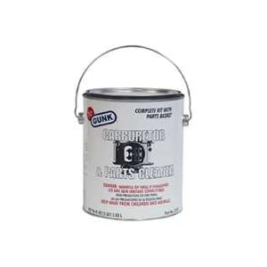
Conventional cleaning methods like throttle body cleaner aren’t very effective. The best method is a soak type cleaner used for carburetors. If you are into fixing motorcycles, jet skis, snowmobiles or anything else with a small carburetor, you probably have used the one gallon soak cleaners like Gunk or Berryman. One of the two should be available at your local auto parts store for $22-$29. Take the solenoid off the body and set it aside: the carb cleaner will damage some types of plastic parts. Soak the metal body in the carb cleaner overnight. There is a basket to set the parts in while they are soaking. When you finish soaking overnight, twist the stem of the IAB/IAC that sticks out while the blocker valve is seated. This removes any leftover deposits from the blocker valve seat. Rinse the part off with water and blow it dry with compressed air. The IAC/IAB should seal up nicely now. Once it has dried, try blowing through the bottom hole and it should block the air flow. Reassemble and reinstall to check it out.
Gunk Dip type carb & parts soaker:
Setting the base idle speed:
First of all, the idle needs to be adjusted to where the speed is at or below 600 RPM with the IAC disconnected. If you have a wild cam, you may have to raise this figure 100-150 RPM or so. Then the electrical signal through the IAC can vary the airflow through it under computer control. Remember that the IAC can only add air to increase the base idle speed set by the mechanical adjustment. The 600 RPM base idle speed is what you have after the mechanical adjustment. The IAC increases that speed by supplying more air under computer control to raise the RPM’s to 650-725 RPM’s. This figure will increase if you have a wild cam, and may end up between 800-950 RPM
Remember that changing the mechanical idle speed adjustment changes the TPS setting too.
This isn't the method Ford uses, but it does work. Do not attempt to set the idle speed until you have fixed all the codes and are sure that there are no vacuum leaks.
Disconnect the battery negative terminal and turn the headlights on. Leave the battery negative terminal disconnected for 5 minutes or so. Then turn the headlights off and reconnect the battery. This erases the computer settings that may affect idle performance.
Warm the engine up to operating temperature, place the transmission in neutral, and set the parking brake. Turn off lights, A/C, all unnecessary electrical loads. Disconnect the IAC electrical connector. Remove the SPOUT plug. This will lock the ignition timing so that the computer won't change the spark advance, which changes the idle speed. Note the engine RPM: use the mechanical adjustment screw under the throttle body to raise or lower the RPM until you get the 600 RPM mark +/- 25 RPM. A wild cam may make it necessary to increase the 600 RPM figure to 700 RPM or possibly a little more to get a stable idle speed.
Changing the mechanical adjustment changes the TPS, so you will need to set it.
When you are satisfied with the results, turn off the engine, and re-install the SPOUT and reconnect the IAC. The engine should idle with the range of 650-750 RPM without the A/C on or extra electrical loads. A wild cam may make this figure somewhat higher.
An engine that whose idle speed cannot be set at 600 RPM with the IAC disconnected has mechanical problems. Vacuum leaks are the #1 suspect in this case. A vacuum gauge will help pinpoint both vacuum leaks and improperly adjusted valves. A sticking valve or one adjusted too tight will cause low vacuum and a 5"-8" sweep every time the bad cylinder comes up on compression stroke. An extreme cam can make the 600 RPM set point difficult to set. Contact your cam supplier or manufacturer to get information on idle speed and quality
Code 41 or 91. Or 43 Three digit code 172 or 176 - O2 sensor indicates system lean. Look for a vacuum leak or failing O2 sensor.
Revised 11-Jan-2015 to add check for fuel pressure out of range
Code 41 is the passenger side sensor, as viewed from the driver's seat.
Code 91 is the driver side sensor, as viewed from the driver's seat.
Code 172 is the passenger side sensor as viewed from the driver's seat.
Code 176 is the driver side sensor, as viewed from the driver's seat.
Code 43 is not side specific according to the Probst Ford Fuel injection book.
The computer sees a lean mixture signal coming from the O2 sensors and tries to compensate by adding more fuel. Many times the end result is an engine that runs pig rich and stinks of unburned fuel.
The following is a Quote from Charles O. Probst, Ford fuel Injection & Electronic Engine control:
"When the mixture is lean, the exhaust gas has oxygen, about the same amount as the ambient air. So the sensor will generate less than 400 Millivolts. Remember lean = less voltage.
When the mixture is rich, there's less oxygen in the exhaust than in the ambient air , so voltage is generated between the two sides of the tip. The voltage is greater than 600 millivolts. Remember rich = more voltage.
Here's a tip: the newer the sensor, the more the voltage changes, swinging from as low as 0.1 volt to as much as 0.9 volt. As an oxygen sensor ages, the voltage changes get smaller and slower - the voltage change lags behind the change in exhaust gas oxygen.
Because the oxygen sensor generates its own voltage, never apply voltage and never measure resistance of the sensor circuit. To measure voltage signals, use an analog voltmeter with a high input impedance, at least 10 megohms. Remember, a digital voltmeter will average a changing voltage." End Quote
Testing the O2 sensors 87-93 5.0 Mustangs
Measuring the O2 sensor voltage at the computer will give you a good idea of how well they are working. You'll have to pull the passenger side kick panel off to gain access to the computer connector. Remove the plastic wiring cover to get to the back side of the wiring. Use a safety pin or paper clip to probe the connections from the rear.
Disconnect the O2 sensor from the harness and use the body side O2 sensor harness as the starting point for testing. Do not measure the resistance of the O2 sensor , you may damage it. Resistance measurements for the O2 sensor harness are made with one meter lead on the O2 sensor harness and the other meter lead on the computer wire or pin for the O2 sensor.
Backside view of the computer wiring connector:
87-90 5.0 Mustangs:
Computer pin 43 Dark blue/Lt green – LH O2 sensor
Computer pin 29 Dark Green/Pink – RH O2 sensor
The computer pins are 29 (L\RH O2 with a dark green/pink wire) and 43 (LH O2 with a dark blue/pink wire). Use the ground next to the computer to ground the voltmeter. The O2 sensor voltage should switch between .2-.9 volt at idle.
91-93 5.0 Mustangs:
Computer pin 43 Red/Black – LH O2 sensor
Computer pin 29 Gray/Lt blue – RH O2 sensor
The computer pins are 29 (LH O2 with a Gray/Lt blue wire) and 43 (RH O2 with a Red/Black wire). Use the ground next to the computer to ground the voltmeter. The O2 sensor voltage should switch between .2-.9 volt at idle.
Testing the O2 sensors 94-95 5.0 Mustangs
Measuring the O2 sensor voltage at the computer will give you a good idea of how well they are working. You'll have to pull the passenger side kick panel off to gain access to the computer connector. Remove the plastic wiring cover to get to the back side of the wiring. Use a safety pin or paper clip to probe the connections from the rear. The computer pins are 29 (LH O2 with a red/black wire) and 27 (RH O2 with a gray/lt blue wire). Use pin 32 (gray/red wire) to ground the voltmeter. The O2 sensor voltage should switch between .2-.9 volt at idle.
Note that all resistance tests must be done with power off. Measuring resistance with a circuit powered on will give false readings and possibly damage the meter. Do not attempt to measure the resistance of the O2 sensors, it may damage them.
Testing the O2 sensor wiring harness
Most of the common multimeters have a resistance scale. Be sure the O2 sensors are disconnected and measure the resistance from the O2 sensor body harness to the pins on the computer. Using the Low Ohms range (usually 200 Ohms) you should see less than 1.5 Ohms.
87-90 5.0 Mustangs:
Computer pin 43 Dark blue/Lt green – LH O2 sensor
Computer pin 29 Dark Green/Pink – RH O2 sensor
Disconnect the connector from the O2 sensor and measure the resistance:
From the Dark blue/Lt green wire in the LH O2 sensor harness and the Dark blue/Lt green wire on the computer pin 43
From the Dark Green/Pink wire on the RH Os sensor harness and the Dark Green/Pink wire on the computer pin 29
91-93 5.0 Mustangs:
Computer pin 43 Red/Black – LH O2 sensor
Computer pin 29 Gray/Lt blue – RH O2 sensor
Disconnect the connector from the O2 sensor and measure the resistance:
From the Red/Black wire in the LH O2 sensor harness and the Red/Black wire on the computer pin 43
From the Dark Green/Pink Gray/Lt blue wire on the RH Os sensor harness and the Gray/Lt blue wire on the computer pin 29
94-95 5.0 Mustangs:
Computer pin 29 Red/Black – LH O2 sensor
Computer pin 27 Gray/Lt blue – RH O2 sensor
From the Red/Black wire in the LH O2 sensor harness and the Red/Black wire on the computer pin 29
From the Dark Green/Pink Gray/Lt blue wire on the RH Os sensor harness and the Gray/Lt blue wire on the computer pin 27
There is a connector between the body harness and the O2 sensor harness. Make sure the connectors are mated together, the contacts and wiring are not damaged and the contacts are clean and not coated with oil.
The O2 sensor ground (orange wire with a ring terminal on it) is in the wiring harness for the fuel injection wiring. I grounded mine to one of the intake manifold bolts
Check the fuel pressure – the fuel pressure is 37-41 PSI with the vacuum disconnected and the engine idling. Fuel pressure out of range can cause the 41 & 91 codes together. It will not cause a single code, only both codes together.
Make sure you have the proper 3 wire O2 sensors. Only the 4 cylinder cars used a 4 wire sensor, which is not compatible with the V8 wiring harness.
Replace the O2 sensors in pairs if replacement is indicated. If one is weak or bad, the other one probably isn't far behind.
Code 41 can also be due to carbon plugging the driver’s side Thermactor air crossover tube on the back of the engine. The tube fills up with carbon and does not pass air to the driver’s side head ports. This puts an excess amount of air in the passenger side exhaust and can set the code 41. Remove the tube and clean it out so that both sides get good airflow: this may be more difficult than it sounds. You need something like a mini rotor-rooter to do the job because of the curves in the tube. Something like the outer spiral jacket of a flexible push-pull cable may be the thing that does the trick.
If you get only code 41 and have changed the sensor, look for vacuum leaks. This is especially true if you are having idle problems. The small plastic tubing is very brittle after many years of the heating it receives. Replace the tubing and check the PVC and the hoses connected to it.