Code 12 -Idle Air Bypass motor not controlling idle properly (generally idle too low) - IAB dirty or not working. Take it off and clean it thoroughly with throttle body cleaner. Clean the electrical contacts with non flammable brake parts cleaner at the same time.
Code 21 or 116 – ECT sensor out of range. Broken or damaged wiring, bad ECT sensor.
Note that that if the outside air temp is below 50 degrees F that the test for the
ECT can be in error. This code may go away as the engine warms up, so don't dump the codes
on a cold engine
The ECT sensor has absolutely nothing to do with the temperature gauge. They are
different animals. The ECT sensor is normally located it the RH front of the engine in
the water feed tubes for the heater.
The ACT & ECT have the same thermistor, so the table values are the same
ACT & ECT test data:
Use Pin 46 on the computer for ground for both ECT & ACT to get most accurate
readings.
Pin 7 on the computer - ECT signal in. at 176 degrees F it should be .80 volts
Pin 25 on the computer - ACT signal in. at 50 degrees F it should be 3.5 volts. It is
a good number if the ACT is mounted in the inlet airbox. If it is mounted in the lower
intake manifold, the voltage readings will be lower because of the heat transfer.
Voltages may be measured across the ECT/ACT by probing the connector from
the rear. A pair of safety pins may be helpful in doing this. Use care in doing it
so that you don't damage the wiring or connector.
Here's the table :
50 degrees F = 3.52 v
68 degrees F = 3.02 v
86 degrees F = 2.62 v
104 degrees F = 2.16 v
122 degrees F = 1.72 v
140 degrees F = 1.35 v
158 degrees F = 1.04 v
176 degrees F = .80 v
194 degrees F = .61
212 degrees F = .47 v
230 degrees F = .36 v
248 degrees F = .28 v
Ohms measures at the computer with the computer disconnected, or at the sensor with the sensor disconnected.
50 degrees F = 58.75 K ohms
68 degrees F = 37.30 K ohms
86 degrees F = 27.27 K ohms
104 degrees F = 16.15 K ohms
122 degrees F = 10.97 K ohms
140 degrees F = 7.60 K ohms
158 degrees F = 5.37 K ohms
176 degrees F = 3.84 K ohms
194 degrees F = 2.80 K ohms
212 degrees F = 2.07 K ohms
230 degrees F = 1.55 K ohms
248 degrees F = 1.18 k ohms
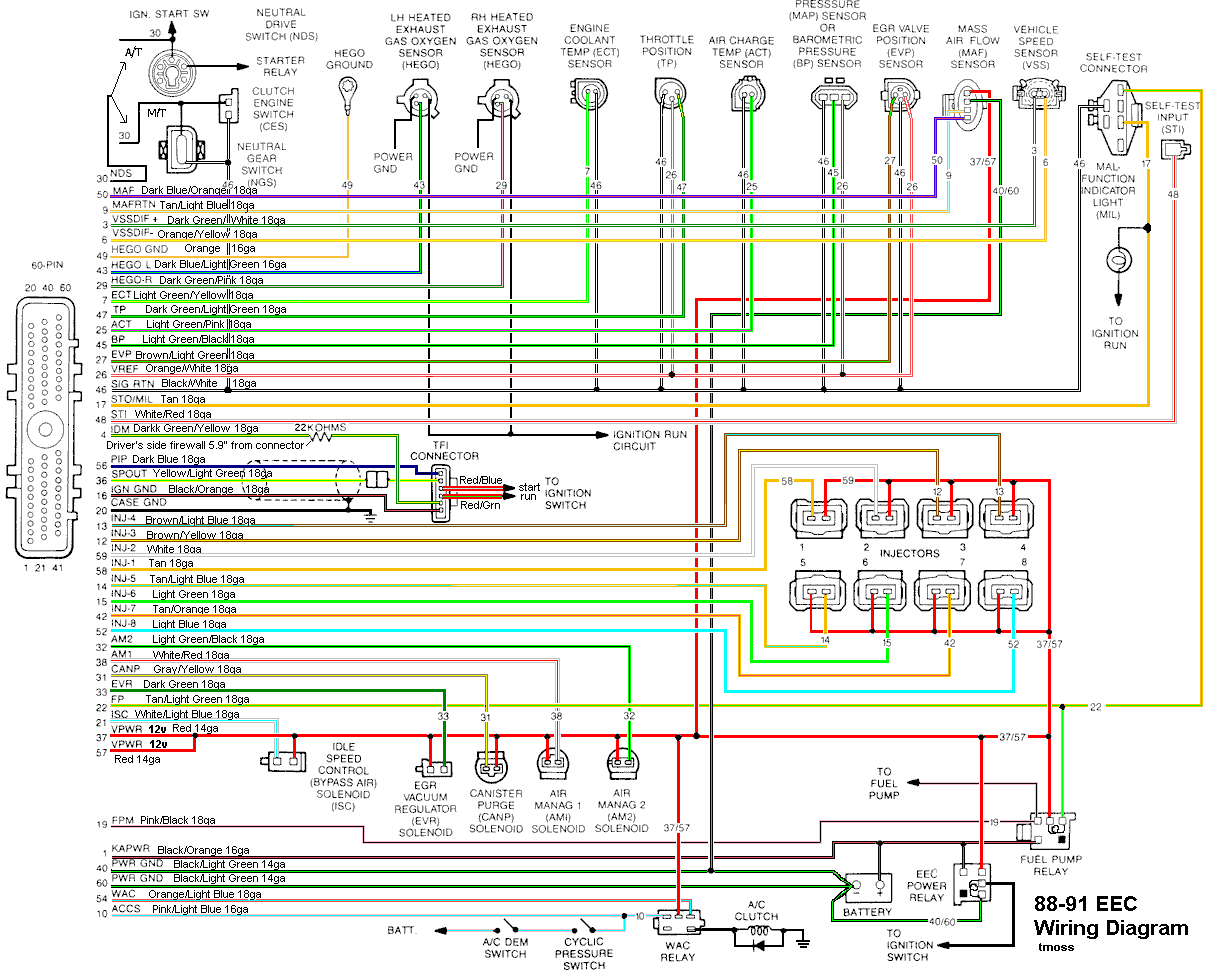
Diagram courtesy of Tmoss & Stang&2birds
See the following website for some help from Tmoss (diagram designer) & Stang&2Birds
(website host) for help on 88-95 wiring
Mustang FAQ - Wiring & Engine Info
Ignition switch wiring
http://www.veryuseful.com/mustang/tech/engine/images/IgnitionSwitchWiring.gif
Fuel, alternator, A/C and ignition wiring
http://www.veryuseful.com/mustang/tech/engine/images/fuel-alt-links-ign-ac.gif
Complete computer, actuator & sensor wiring diagram for 88-91 Mass Air Mustangs
http://www.veryuseful.com/mustang/tech/engine/images/88-91_5.0_EEC_Wiring_Diagram.gif
Vacuum diagram 89-93 Mustangs
http://www.veryuseful.com/mustang/tech/engine/images/mustangFoxFordVacuumDiagram.jpg
Code 33 - Insufficient EGR flow detected.
Look for vacuum leaks, cracked vacuum lines, failed EGR vacuum regulator. Check to see if you have 10” of vacuum at the EGR vacuum connection coming from the intake manifold. Look for electrical signal at the vacuum regulator solenoid valves located on the rear of the passenger side wheel well. Using a test light across the electrical connector, it should flicker as the electrical signal flickers. Remember that the computer does not source any power, but provides the ground necessary to complete the circuit. That means one side of the circuit will always be hot, and the other side will go to ground or below 1 volt as the computer switches on that circuit.
Check for resistance between the brown/lt green wire on the EGR sensor and pin 27 on the computer: you should have less than 1.5 ohm.
See the following website for some help from Tmoss (diagram designer) & Stang&2Birds (website host)
http://www.veryuseful.com/mustang/tech/engine/images/fuel-alt-links-ign-ac.gif
http://www.veryuseful.com/mustang/tech/engine/images/88-91eecPinout.gif
EGR test procedure courtesy of cjones
to check the EGR valve:
bring the engine to normal temp.
connect a vacuum pump to the EGR Valve or
see the EGR test jig drawing below. Connnect the test jig or to directly to manifold vacuum.
Do not connect the EGR test jig to the EVR (Electronic Vacuum Regulator).
apply 5in vacuum to the valve.
Using the test jig, use your finger to vary the vacuum
if engine stumbled or died then EGR Valve and passage(there is a passageway through the heads and intake) are good.
if engine did NOT stumble or die then either the EGR Valve is bad and/or the passage is blocked.
if engine stumbled,
connect EGR test jig to the hose coming off of the EGR Valve.
Use your finger to cap the open port on the vacuum tee.
snap throttle to 2500 RPM (remember snap the throttle don't hold it there).
did the vacuum gauge show about 2-5 in vacuum?
if not the EVR has failed
EGR test jig
The operation of the EGR vacuum regulator can be checked by using a test light applied across the wiring connector. Jumper the computer into self test mode and turn the key on but do not start the engine. You will hear all the actuators (including the EVR vacuum regulator) cycle. Watch for the light to flicker: that means the computer has signaled the EGR vacuum regulator successfully.
Codes 44 & 94 - AIR system inoperative - Air Injection. Check vacuum lines for leaks, & cracks.
Revised 28-Oct-2009 to correct code definitions and operation.
Code 44 RH side air not functioning.
Code 94 LH side air not functioning.
The computer uses the change in the O2 sensor readings to detect operation of the Thermactor control valves. When the dump valve opens, it reduces the O2 readings in the exhaust system. Then it closes the dump valve and the O2 readings increase. By toggling the dump valve (TAB), the computer tests for the 44/94 codes.
Failure mode is usually due to a clogged air crossover tube, where one or both sides of the tube clog with carbon. The air crossover tube mounts on the back of the cylinder heads and supplies air to each of the Thermactor air passages cast into the cylinder heads. When the heads do not get the proper air delivery, they set codes 44 & 94, depending on which passage is clogged. It is possible to get both 44 & 94, which would suggest that the air pump or control valves are not working correctly, or the crossover tube is full of carbon or missing.
Testing the system:
Disconnect the big hose from smog pump: with the engine running you should feel air output. Reconnect
the smog pump hose & apply vacuum to the first vacuum controlled valve: Its purpose is to either dump
the pump's output to the atmosphere or pass it to the next valve.
The next vacuum controlled valve directs the air to either the cylinder heads when the engine is cold or
to the catalytic converter when the engine is warm. Disconnect the big hoses from the back side of the
vacuum controlled valve and start the engine. Apply vacuum to the valve and see if the airflow changes
from one hose to the next.
The two electrical controlled vacuum valves mounted on the rear of the passenger side wheel well turn the
vacuum on & off under computer control. Check to see that both valves have +12 volts on the red wire.
Then ground the white/red wire and the first solenoid should open and pass vacuum. Do the same thing to
the light green/black wire on the second solenoid and it should open and pass vacuum.
Remember that the computer does not source power for any actuator or relay, but provides the ground
necessary to complete the circuit. That means one side of the circuit will always be hot, and the other side
will go to ground or below 1 volt as the computer switches on that circuit.
The computer provides the ground to complete the circuit to power the solenoid valve that turns the
vacuum on or off. The computer is located under the passenger side kick panel. Remove the kick panel &
the cover over the computer wiring connector pins. Check Pin 38 Solenoid valve #1 that provides vacuum
to the first Thermactor control valve for a switch from 12-14 volts to 1 volt or less. Do the same with pin
32 solenoid valve #2 that provides vacuum to the second Thermactor control valve. Starting the engine
with the computer jumpered to self test mode will cause all the actuators to toggle on and off. If after
doing this and you see no switching of the voltage on and off, you can start testing the wiring for shorts to
ground and broken wiring. An Ohm check to ground with the computer connector disconnected & the
solenoid valves disconnected should show open circuit between the pin 32 and ground and again on pin 38
and ground. In like manner, there should be less than 1 ohm between pin 32 and solenoid valve #2 and pin
38 & Solenoid valve #1.
If after checking the resistance of the wiring & you are sure that there are no wiring faults, start looking at the
solenoid valves. If you disconnect them, you can jumper power & ground to them to verify operation. Power &
ground supplied should turn on the vacuum flow, remove either one and the vacuum should stop flowing.
Typical resistance of the solenoid valves is in the range of 20-70 Ohms.
See the following website for some help from Tmoss (diagram designer) & Stang&2Birds (website host)
http://www.veryuseful.com/mustang/tech/engine/images/fuel-alt-links-ign-ac.gif
http://www.veryuseful.com/mustang/tech/engine/images/88-91eecPinout.gif
See
http://forums.stangnet.com/attachment.php?attachmentid=50636&d=1180923382 for a very nice drawing of the Thermactor Air System (smog pump) plumbing
If you have a catalytic converter H pipe, you need to fix these codes. If you don't, then don't worry about them