EFI no start, continued..

stangman16

Active Member
Nov 16, 2004
640
4
29
San Antonio, TX
Okay, got a test light and read the codes off the '66. Here's what I've got in order presented:

1.23.2007 Results

(21) ECT (Engine Coolant Temp) out of range. Coolant is less than 50degF for KOEO

(22) MAP (vacuum) or BARO signal out of range - MAP

(24) ACT (Air Charge Temperature)/IAT (Intake Air Temperature) sensor voltage out of range. Suspect ACT sensor and harness.

(81) TAD or AM-2 (Thermactor Air Diverter)/ Secondary Air Injection Bypass (AIRB) solenoid circuit failure

(82) TAB or AM-1 (Thermactor Air Bypass)/ Secondary Air Injection Diverter (AIRD) solenoid circuit failure

(85) CANP (Canister Purge) solenoid circuit failure

(84) EVR (EGR Vacuum Regulator) solenoid circuit failure

(95) Fuel Pump Monitor circuit problems, processor to pump motor ground.

There was the 6-9 second pause followed by the separator code # repeated twice.

(15) No Keep Alive Memory power to PCM pin 1 or bad PCM (Memory Test Failure)

-------------------------

Alright, I don't have TAB/TAD, CANP, and the EGR hooked up, but I do have the ford fuel injection EGR eliminator so I'm not sure why it's throwing that code. As for the ECT since the engine doesn't start I'm ruling that one to be okay. I guess I need a new MAP sensor unless it's throwing that code because it is ~45° outside..?

for 24 = the ACT is brand new, could it throw this due to the temp – or is it definitely in the harness?

for 95 = does anyone have a schematic of where the ground should go? I'm guessing I have it in the wrong place. I have the fuel pump power relay wire going to the inertia switch, then to the pump, and I have the ground wire off the pump to the body of the car.

for 15 = I hope this separator code doesn't mean my PCM is toast.....

I'm new to the fuel injection diagnosis, etc. - would you say the above codes are enough to keep the engine from firing over, or is there most likely an underlying issue far worse then the codes I'm receiving?

Thank you jrichker for the diagram info!
 
You might want to add what year the donor harness is from, as SD wiring is a bit different than MAF stuff (or MAF converted stuff sometimes).

Also, does it crank but not start? Do you have spark or injector pulsing? I guess I missed the other thread or background info.

Good luck.
 
No, my apologies - I posted the other one in classic tech.

The harness I'm not sure what year it is from, but it is a MAF harness and A9L computer. On the test connector I believe I saw the wire for the check engine light - would that be '89-'93?

It cranks but doesn't start, I've checked the firing order on the injector harness since I have the 302 non-HO firing order. I have spark and I believe that I have fuel - I need to get a noid light to ensure the injectors are firing. But I did test the voltage at the injector red wire and I do have power there.

I went through jrichkers no-start checklist and if my injectors are firing, then I get to step 4. I've tried spraying starter fluid in through the throttle body and it just kept cranking, didn't sound any different or as if it was going to fire.

Other than the codes listed above, I'm stumped.

"4.) Spark & fuel pressure OK.

A.) Failed IAB (no airflow to start engine). Press the throttle ¼ way down and try to start the car.
B.) Failed computer (not very likely)
C.) Engine ignition or cam timing off: only likely if the engine has been worked on recently).
D.) Firing order off: HO & 351 use a different firing order from the non HO engines.
HO & 351W 1-3-7-2-6-5-4-8
Non HO 1-5-4-2-6-3-7-8
E.) No start when hot - Press the throttle to the floor & try starting it if you get this far. If it starts, replace the ECT. "
 
The last time I encountered this problem it was a bad coil. It had just enough spark to jump the gap when there was no compression.

The code 22 is a real problem. The engine has no idea where to set the barometric pressure, so it has no idea of how much fuel is needed. Couple that with an ACT fault, and the air/fuel mixture could be anywhere.
 
I'm not real savvy with the HO vs non-HO intermingling, but did you have to switch some injector wiring around so the computer was in synch with the non-HO firing order?

EDIT: NM - you covered that. I'll learn to read one of these days.

For it to not even cough with ether was what made me wonder initially..........

I'm sure JR will get you up and running. :nice:

Good luck.
 
The last time I encountered this problem it was a bad coil. It had just enough spark to jump the gap when there was no compression.

The code 22 is a real problem. The engine has no idea where to set the barometric pressure, so it has no idea of how much fuel is needed. Couple that with an ACT fault, and the air/fuel mixture could be anywhere.

I've got a brand new Ford Racing coil - looks good being all shiny in the old engine comparment :)
I'll get a new MAP sensor ASAP - thanks for explaining what's happening with it and the A/F ratio.

What about the 95 & 15 error codes? I'm worried about them both, mainly the 15 and I hope that my PCM is okay.
For the ACT, I will check the harness to ensure it's wired correctly.

HISSIN50 said:
For it to not even cough with ether was what made me wonder initially..........

I actually had it wired up for 5.0 HO firing order, and when I checked the wiring and changed it over to the non-HO, I could not tell a difference with how it was cranking with or without ether. So I'll get the MAP sensor and check into the fuel pump wiring to make sure I've got it straight and hope that gets it finished.

Thank you both!
 
Does the computer possibly have a chip installed on it? I had a code 15 bring thrown on my A9L and I couldn't figure out why. I finally pulled the ECU out of the kick panel and it had a damn hypertech chip on it. I removed the chip and no more code 15. If you dont have a chip check pin 1 on the ECU and see if your getting 12V there all the time. If not then that is your problem. If you do have 12V there then the problem is more than likely your ECU itself. Good Luck.
 
Yea, the ECU seal where the chip would go is not broken, so no mods there. I'll check the Pin 1 to see if it's getting 12V there all the time. thanks!

As for the fuel pump code (95), should I just run a ground wire to the ( - ) side of the battery? When I turn the ignition in Run mode, I hear the pump prime for about 3 seconds usually, once in a blue moon it'll be 4-5 seconds.
 
Code 21 – ECT sensor out of range. Broken or damaged wiring, bad ECT sensor.
Note that that if the outside air temp is below 50 degrees F that the test for the
ECT can be in error.


The ECT sensor has absolutely nothing to do with the temperature gauge. They are different animals.
The ECT sensor is normally located it the RH front of the engine in the water feed tubes for the heater.

The ACT & ECT have the same thermistor, so the table values are the same

ACT & ECT test data:

Use Pin 46 on the computer for ground for both ECT & ACT to get most accurate
readings.

Pin 7 on the computer - ECT signal in. at 176 degrees F it should be .80 volts

Pin 25 on the computer - ACT signal in. at 50 degrees F it should be 3.5 volts. It is
a good number if the ACT
is mounted in the inlet airbox. If it is mounted in the lower intake manifold, the voltage readings will be lower because of the heat transfer.

Voltages may be measured across the ECT/ACT by probing the connector from
the rear. A pair of safety
pins may be helpful in doing this. Use care in doing it so that you don't damage the wiring or connector.

Here's the table :

68 degrees F = 3.02 v
86 degrees F = 2.62 v
104 degrees F = 2.16 v
122 degrees F = 1.72 v
140 degrees F = 1.35 v
158 degrees F = 1.04 v
176 degrees F = .80 v
194 degrees F = .61

Note that all resistance tests must be done with power off. Measuring resistance
with a circuit powered on will give false readings and possibly damage the meter.


Ohms measures at the computer with the computer disconnected, or at the sensor
with the sensor disconnected.
50 degrees F = 58.75 K ohms
68 degrees F = 37.30 K ohms
86 degrees F = 27.27 K ohms
104 degrees F = 16.15 K ohms
122 degrees F = 10.97 K ohms
140 degrees F = 7.60 K ohms
158 degrees F = 5.37 K ohms
176 degrees F = 3.84 K ohms
194 degrees F = 2.80 K ohms

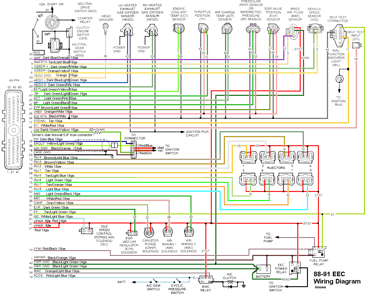
Diagram courtesy of Tmoss & Stang&2birds

88-91_5.0_EEC_Wiring_Diagram.gif


See the following website for some help from Tmoss (diagram designer) & Stang&2Birds
(website host) for help on 88-95 wiring http://www.veryuseful.com/mustang/tech/engine/

http://www.veryuseful.com/mustang/tech/engine/images/IgnitionSwitchWiring.gif

http://www.veryuseful.com/mustang/tech/engine/images/fuel-alt-links-ign-ac.gif

http://www.veryuseful.com/mustang/tech/engine/images/88-91_5.0_EEC_Wiring_Diagram.gif


Code 22 MAP (vacuum) or BARO signal out of range. The MAP or BARO sensor is pretty much the
same sensor for both Mass Air & Speed Density cars. The main difference is where it is connected.
Mass Air cars vent it to the atmosphere, while Speed Density cars connect it to the intake manifold vacuum.
Its purpose is to help set a baseline for the air/fuel mixture by sensing changes in barometric pressure.
The MAP or BAP sensor puts out a 5 volt square wave that changes frequency with variations in atmospheric pressure.
The base is 154 HZ at 29.92" of mercury - dry sunny day at sea level, about 68-72 degrees. You need an
oscilloscope or frequency meter to measure it. There is no way you can use a common cheap voltmeter
or DVM to accurately measure the output signal.

The MAP/BARO sensor is mounted on the firewall behind the upper manifold.

Baro or MAP test using frequency meter - run the test key on engine off. The noise from the ignition system
will likely upset the frequency meter. I used a 10 x oscilloscope probe connected from the frequency meter
to the MAP/BAP to reduce the jitter in the meter's readout.

If it is defective, your air/fuel ratio will be off and the car’s performance & emissions will suffer

Some basic checks you can make to be sure that the sensor is getting power & ground:
Note that all resistance tests must be done with power off. Measuring resistance with a
circuit powered on will give false readings and possibly damage the meter.

Check the resistance between the black/white wire on the MAP/BARO sensor and then the black/white
wire on the EGR and the same wire on the TPS. It should be less than 1 ohm. Next check the resistance
between the black/white wire and the negative battery cablet. It should be less than 1.5 ohm.

The following power on check requires you to turn the ignition switch to the Run position.
Use a DVM to check for 5 volts on the orange/white wire. If it is missing, look for +5 volts at the orange/white
wire on the TPS or EGR sensors. Use the black/white wire for the ground for the DVM.

Code 24 - Intake Air Temperature (ACT) sensor out of range. Bad sensor, bad wiring. The ACT for
Mustangs built before 95 is in the #5 intake runner. It measures the air temperature in the
intake to help computer the proper air/fuel ratio.

Note that that if the outside air temp is below 50 degrees F that the test for the ACT can be in error.

ACT & ECT test data:

The ACT & ECT have the same thermistor, so the table values are the same

Pin 7 on the computer - ECT signal in. at 176 degrees F it should be .80 volts

Pin 25 on the computer - ACT signal in. at 50 degrees F it should be 3.5 volts. It is a good number if the ACT i
s mounted in the inlet airbox. If it is mounted in the lower intake manifold, the voltage readings will be
lower because of the heat transfer. Here's the table :

68 degrees F = 3.02 v
86 degrees F = 2.62 v
104 degrees F = 2.16 v
122 degrees F = 1.72 v
140 degrees F = 1.35 v
158 degrees F = 1.04 v
176 degrees F = .80 v
194 degrees F = .61

Note that all resistance tests must be done with power off. Measuring resistance with a
circuit powered on will give false readings and possibly damage the meter.


Ohms measures at the computer with the computer disconnected, or at the sensor with the sensor disconnected.
50 degrees F = 58.75 K ohms
68 degrees F = 37.30 K ohms
86 degrees F = 27.27 K ohms
104 degrees F = 16.15 K ohms
122 degrees F = 10.97 K ohms
140 degrees F = 7.60 K ohms
158 degrees F = 5.37 K ohms
176 degrees F = 3.84 K ohms
194 degrees F = 2.80 K ohms

Cods 81, 82, 84 & 85 are for thr pollution control equipment that you probably don't have installed.
They shouldn't hurt performance, and the fix is easy. You solder a 70 ohm 2 watt resistor on each pair
of leads that go to the missing devices. Use some heat shrink tubing to cover the resistor & solder joints to make it look nice.

Code 95 - the following test path is for 86-90 model Mustangs.

The 95 code is because at one time or another, the fuel pump relay hiccupped and didn't provide power
the pump when the computer told it to run. Sometimes this is a one time thing, other times it is a no r
un or runs poorly condition.

To help troubleshoot the 95 code, follow this link for a wiring diagram http://www.autozone.com/images/cds/gif/large/0900823d80167162.gif

Using the diagram, check the red/black wire from the fuel pump relay: you should see 12 volts or so.
If not, check the inertia switch: on a hatch it is on the driver’s side by the taillight. Look for a black rubber
plug that pops out: if you don't find it, then loosen up the plastic trim. Check for voltage on both sides
of the switch. If there is voltage on both sides, then check the Pink/black wire on the fuel pump relay: it is
the power feed to the fuel pump. No voltage there, check the Orange/Lt blue wire, it is the power
feed to the fuel pump relay & has a fuse link in it. If there is good voltage there & at the Pink/black wire, swap the relay.

Some Mass Air conversions neglect to run the extra fuel pump wire, and they always have a 95 code.
See http://www.stangnet.com/tech/maf/massairconversion.html for more information on the Mass Air wiring conversion.
 
Okay, got a new Map sensor, installed it and I'm showing the same codes. I disconnected the battery for 15 mins and checked codes again and they're the exact same - even before I tried cranking it.

Bought a noid light and checked for injectors firing, they are not. I do have power to the red wire 12v on the injectors, and at the salt & pepper shakers.

I'm trying to find someone in San Antonio or Austin, TX that will hook up my computer in their car to see if it's faulty - but I'm not in luck on this.
Could that separator code of 15 definitely mean my PCM is bad? To check power at Pin 1, do I need to disconnect the computer and check it like that? I'm a real rookie with EFI & electronics diagnosing, please bare with me.
 
Okay, got a new Map sensor, installed it and I'm showing the same codes. I disconnected the battery for 15 mins and checked codes again and they're the exact same - even before I tried cranking it.

Bought a noid light and checked for injectors firing, they are not. I do have power to the red wire 12v on the injectors, and at the salt & pepper shakers.

I'm trying to find someone in San Antonio or Austin, TX that will hook up my computer in their car to see if it's faulty - but I'm not in luck on this.
Could that separator code of 15 definitely mean my PCM is bad? To check power at Pin 1, do I need to disconnect the computer and check it like that? I'm a real rookie with EFI & electronics diagnosing, please bare with me.

Disconnecting the power will clear the computer of all codes.

The code 22 MAP test included some electrical checks to do before replacing the sensor.
I highly recommend that you do them.

The code 15 voltage check is done with the computer connected or disconnected. Probe the wiring from
the back side of the connector using a safety pin to do the job.


Cranks OK, but No Start Checklist for Fuel Injected Mustangs

Revised 20-Jan-2007 to include TPS voltage out of range fault.
All text applies to
all models unless stated otherwise.


Note: 94-95 specific changes are in red

1.) Remove push on connector from starter solenoid and turn ignition switch on.
Place car in neutral or Park and set the parking brake. Remove the coil wire from distributor
& and hold it 3/8” away from the engine block. Jumper the screw to the big bolt on the starter
solenoid that has the battery wire connected to it. You should get a nice fat blue spark.
Most of the items are electrical in nature, so a test light, or even better, a voltmeter,
is helpful to be sure they have power to them.
No spark, possible failed items in order of their probability:
A.) MSD or Crane ignition box if so equipped
B.) Coil
C.) TFI module
D.) PIP sensor in distributor. See paragraph 5A - a noid light will tell if the pip is working by flashing
when the engine is cranking.
E.) No ECC or computer power - ECC or computer relay failure
86-93 models only:
ECC relay next to computer - look for 12 volts at the fuel injector red wires
94-95 models only: EEC or PCM power relay in the constant control relay module. Look for 12 volts at the fuel injector red wires.
F.) No ECC or computer power - fuse or fuse link failure
86-93 models only: Fuse links in wiring harness - look for 12 volts at the fuel injector red wires. All the fuse
links live in a bundle up near the starter solenoid.
94-95 models only: 20 amp EEC fuse in the engine compartment fuse box. Look for 12 volts at the fuel injector red wires.
G.) Ignition switch - look for 12 volts at the ignition coil red/lt green wire.
H.) Computer
J.) Engine fires briefly, but dies immediately when the key is released to the Run position. Crank the
engine & when it fires off, pull the small push on connector (red wire) off the starter relay (Looks
like it is stuck on a screw). Hold the switch in the crank position: if it continues to run there is a
problem with either the ignition switch or TFI module. Check for 12 volts at the red/green wire
on the coil with the switch in the Run position. Good 12 volts, then replace the TFI.

See the following links for wiring diagrams...

http://www.autozone.com/servlet/UiB..._us/0900823d/80/16/71/3c/0900823d8016713c.jsp for 79-88 model cars
Computer/fuel pump/ignition wiring diagram, 86 model http://www.autozone.com/images/cds/gif/large/0900823d80167158.gif
Computer/fuel pump/ignition wiring diagram, 87 model http://www.autozone.com/images/cds/gif/large/0900823d8016715e.gif
Computer/fuel pump/ignition wiring diagram, 88 model http://www.autozone.com/images/cds/gif/large/0900823d80167162.gif

http://www.autozone.com/servlet/UiB..._us/0900823d/80/19/59/5a/0900823d8019595a.jsp for 89-93 model cars
Computer/fuel pump/ignition wiring diagram, 89-90 cars http://www.autozone.com/images/cds/gif/large/0900823d8019595f.gif
Computer/fuel pump/ignition wiring diagram, 91-93 cars
http://www.autozone.com/images/cds/gif/large/0900823d80195960.gif

http://www.autozone.com/servlet/UiBroker?ForwardPage=/az/cds/en_us/0900823d/80/1d/db/3c/0900823d801ddb3c.jsp
for 94-98 model cars


2.) Spark at coil wire, pull #1 plug wire off at the spark plug and check to see spark.
No spark, possible failed items in order of their probability:
A.) Moisture inside distributor – remove cap, dry off & spray with WD40
B.) Distributor cap
C.) Rotor
D.) Spark Plug wires
E.) Coil weak or intermittent - you should see 3/8" fat blue spark with a good coil


3.) Spark at spark plug, but no start.
Next, get a can of starting fluid (ether) from your local auto parts store: costs a $1.30 or so.
Then pull the air duct off at the throttle body elbow, open the throttle, and spray the ether in it.
Reconnect the air duct and try to start the car. Do not try to start the car without reconnecting the air duct.
Two reasons:
1.) If it backfires, the chance for a serious fire is increased.
2.) On Mass Air cars, the computer needs to measure the MAF flow once the engine starts.
If it starts then, you have a fuel management issue. Continue the checklist with emphasis of
fuel related items that follow. If it doesn’t, then it is a computer or timing issue: see Step 4.​

Clue – listen for the fuel pump to prime when you first turn the ignition switch on.
It should run for 5-20 seconds and shut off. To trick the fuel pump into running, find the ECC
test connector and jump the connector in the Upper RH corner to ground.
attachment.php


If the relay & inertia switch are OK, you will have power to the pump. Check fuel pressure –
remove the cap from the Schrader valve behind the alternator and depress the core. Fuel
should squirt out, catch it in a rag. Beware of fire hazard when you do this. In pinch you
can use a tire pressure gauge to measure the fuel pressure. It may not be completely accurate,
but you will have some clue as to how much pressure you have. If you have any doubts about
having sufficient fuel flow/pressure, rent a fuel pressure test gauge from the auto parts store.
That will tell you for sure if you have adequate fuel pressure.


4.) No fuel pressure, possible failed items in order of their probability:
A.) Tripped inertia switch – Coupe & hatch cars hide it under the plastic trim covering
the driver's side taillight. Use the voltmeter or test light to make sure you have power to both sides of the switch
B.) Fuel pump power relay – located under the driver’s seat in most stangs built before 92.
On 92 and later model cars it is located below the Mass Air Flow meter. Look for 12 volts
at the Pink/Black wire on the fuel pump relay.
C.) Clogged fuel filter
D.) Failed fuel pump
E.) 86-93 models only: Blown fuse link in wiring harness. Look for 12 volts at the Orange/Lt Blue
wire on the fuel pump relay. The fuse links live in the wiring harness near the starter solenoid.
94-95 models only: 20 amp fuel pump fuse in the engine compartment fuse box. Look for 12 volts at the
Dark green/yellow wire on the constant control relay module.

F.) Fuel pressure regulator failed. Remove the vacuum line from the regulator and inspect for fuel
escaping while the pump is running. If fuel is coming out the vacuum port, the regulator has failed.

5.) Fuel pressure OK, the injectors are not firing.
A.) A noid light available from any auto parts store, is one way to test the injector wiring.
The noid light plugs into the fuel injector harness in place of any easily accessible injector.
B.) I like to use an old injector with compressed air applied to the injector where the fuel
rail would normally connect. I hook the whole thing up, apply compressed air to the
injector and stick it in a paper cup of soapy water. When the engine cranks with the ignition
switch on, if the injector fires, it makes bubbles. Cheap if you have the stuff laying around,
and works good too.
C.) Pull an injector wire connector off and look for 12 volts on the red wire when the ignition switch is on.
D.) No power, then look for problems with the 10 pin connecter (salt & pepper shakers at
the rear of the upper manifold).
E.) No power and the 10 pin connections are good: look for broken wiring between the
orange/black wire on the ECC relay and the red wire for the 10 pin connectors.
G.) TPS voltage exceeds 3.7 volts with the throttle closed. This will shut off the
injectors, since the computer uses this strategy to clear a flooded engine. Use
a DVM, a pair of safety pins, and probe the black/white and green wires to
measure the TPS voltage. It should be .5-.99 volts with the key on, engine
not running. Note that if the black/white wire (signal ground) has a bad connection,
you will get some strange readings. Make a second measurement using the battery
post as the ground to eliminate any ground problems. If the readings are different
by more than 5%, you may have a high resistance condition in the black/white
signal ground circuit.


6.) Spark & fuel pressure OK.
A.) Failed IAB (no airflow to start engine). Press the throttle ¼ way down and try to start the car.
B.) Failed computer (not very likely)
C.) Engine ignition or cam timing off: only likely if the engine has been worked on recently).
D.) Firing order off: HO & 351 use a different firing order from the non HO engines.
HO & 351W 1-3-7-2-6-5-4-8
Non HO 1-5-4-2-6-3-7-8
E.) No start when hot - Press the throttle to the floor & try starting it if you get this far. If it starts, replace the ECT.