Electrical Engine coolant temperature sensor

twohawks777@cox

Active Member
Feb 6, 2012
108
15
28
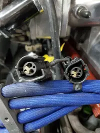
Which of the two pigtails plug into the engine coolant temperature sensor. One is the ETS and the other is canister purge solenoid. How can I tell the difference
20210313_121300.jpg
 
  • Sponsors (?)


Both pigtails will fit the sensor on the ECT sensor and I no longer have a canisterpurge solenoid. I believe they both are two wire only differences is the colors of the four wires.
 
I thought I knew where the color wire diagram of the engine is, but cannot find it. @jrichker @tmoss @General karthief can you help link or post it for @twohawks777@cox and me? I cannot find my 3 ring binder of printouts after the last move. Thanks.

edit, My car is hiding from the storm this weekend. It will not take much for us to be in the 20” of snow instead of the 4” of rain until Tuesday forecast area.
 
  • Like
  • Haha
Reactions: 1 users
I never noticed they were the same, one of mine is longer by a couple inches IIRC, that one I used for the purge solenoid, veryuseful.com is a good place to go for wire colors because difference in years, I may even have saved it,
Someplace
Maybe I'll look for it
Stand by, :runaway:
 
  • Useful
  • Like
Reactions: 1 users
The following are diagrams courtesy of Tmoss & Stang&2birds

Complete computer, actuator & sensor wiring diagram for 91-93 Mass Air Mustangs
91-93_5.0_EEC_Wiring_Diagram.gif


Complete computer, actuator & sensor wiring diagram for 88-90 Mass Air Mustangs
88-91_5.0_EEC_Wiring_Diagram.gif


See the following website for some help from Tmoss (diagram designer) & Stang&2Birds (website host) for help on 88-95 wiring; http://www.veryuseful.com/mustang/tech/engine/ Everyone should bookmark this site.[/b]

TFI module wiring for 94-95 Mustang GT
http://www.veryuseful.com/mustang/tech/engine/images/Mustang-94-95-IgnitionControlModule.gif

Complete computer, actuator & sensor wiring diagram for 94-95 Mustangs

Complete computer, actuator & sensor wiring diagram for 91-93 Mass Air Mustangs

Complete computer, actuator & sensor wiring diagram for 88-90 Mass Air Mustangs

5.0 wiring diagram for Fuel Injectors, Sensors, and Actuators

Main body EFI wiring harness

Ignition switch wiring

O2 sensor wiring harness

Vacuum diagram 89-93 Mustangs

HVAC vacuum diagram

TFI module differences & pin out

Fuse box layout

Mustang 5.0 Lights and Radio schematic, by TMoss:
http://www.veryuseful.com/mustang/tech/engine/images/mustangFoxLights-Radio_diag.gif

87-92 power window wiring

93 power window wiring

T5 Cutaway showing T5 internal parts

Visual comparison of the Ford Fuel Injectors, picture by TMoss:

Convertible top motor wiring http://www.veryuseful.com/mustang/tech/engine/images/mustang88VertTopMotorCkt.gif

Engine mounted fuel injector harness

Location of the TPS, IAB, and the 10-pin connectors on a 5.0, picture by TMoss:

Starter circuit

Alternator diagram for 94-95 Mustangs.
 
  • Useful
  • Like
Reactions: 1 users
So after reading the electrical schematics the answer to my question is the pigtail with the green and black wires plug into the engine coolant temperature sensor. The other pigtail wires are red and yellow which plugs into the canister purge solenoid.
 
  • Like
Reactions: 1 user
The plugs are not the same. Only one will physicslly fit the ect. The charcoal plug is mirrored.

172365C3-5EC0-4A7E-9E0B-316080D22782.jpeg


as you have determined, the one with the green wire is for the ECT. The other one won’t fit at all.

5EACCF0C-D817-41B6-808A-D85750657710.jpeg
 
  • Agree
  • Like
Reactions: 1 users
I don't say this often. If this is your picture and you say either will fit..then...sir...you are an idiot.

The one highest in your picture is the plug for the sensor in your picture. Multiple people have told you they both won't plug into that sensor but you persist.

Screenshot_20210315-110727_Chrome.jpg


It's a simple geometrical puzzle. That corner on the sensor will not allow it to plug in....the pins inside the sensor also will not line up to the other connector.

If you are here trolling then congratulations. You've got what you came for. If you really believe they'll both plug in please take a short video clip....upload to youtube...and go to share...click clip board....open a response here....paste link from clip board...and let us see. ( I would apologize and give you a 100 dollar gift card to LMR )

One exception is if this isn't the car in the pic above..and you have the wrong temp sensor.
 
I see the problem.

The second connector is damaged. It shouldn't be able to clip onto the ECT sensor like that if it was fully intact. The "nub" on the ECT is just fitting in the gap on the broken connector. You can see it in the shot below. That connector is just busted, otherwise it normally wouldn't fit.

1615826491918.png