Oh man.
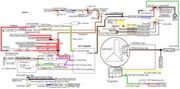
Like I said, I would use green/purple. It shows 12 volts the whole time the AC is turned on.
If you dont want to use that, Blk/yellow is fine. WIth this wire, your fan might constantly stop/start as the compressor cycles. I've worked on a car like this and it was lackluster. THis is why computer-controlled OEM fans have hysteresis built into the controls. THe fan will not shut off for like 30-60 seconds after the AC loses power. This keeps the fan on constantly while the compressor cycles.
Good luck.

 she is in rare form tonight!